Copyrights(c) 2007-2010, Dr. R. R. Stiffler
Spatial Energy
Coherence
Copyrights(c) 2007-2010, Dr. R. R.
Stiffler
All rights reserved.
Unauthorized Copying of this
material is strictly forbidden.
Violation of these Copyrights will be
enforced.
The Hiddink Experiments
|
Experiments based on the work and circuits of Joseph Hiddink(1) with additional and new theoretical views by John Berry(2) and supporting research by Ben Thomas(3)
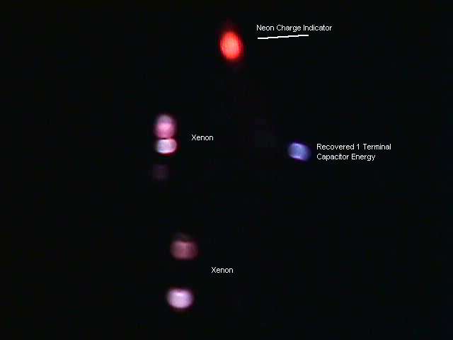
The very first test run produced some interesting results. The Neon is connected between the two copper pickup screens wrapped around the Xenon's. During the plasma condition the Neon would light as shown in the following picture. What should be noted is that the Neon is seeing a DC and not AC potential, as only one electrode of the Neon is glowing. When the plasma was extinguished the Neon would flash brighter but with the opposite electrode conducting. The flash was noticeable although was not considered remarkable.
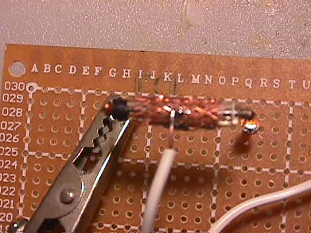
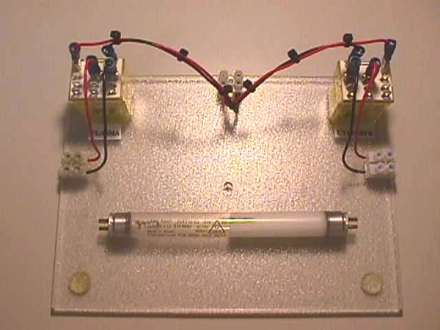
The very first circuit put together used two Xenon's with copper screen wrapped around them for the cylinder portion of the capacitor. The Xenon's and copper screen can be seen in the following picture.
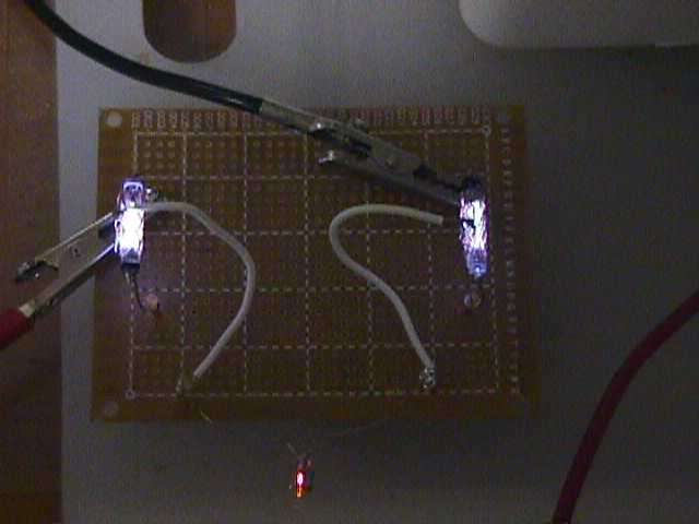
After some adjustments in the voltage going to the Xenon's and changing my manual switching method I was able to obtain the expected AC across the monitor Neon and it can be seen that in this picture both electrodes are ionized. It took a bit of trial and error to get a picture of the turn off arc, but it can be seen on the right side of the board.
For various reasons I took the copper screen off of the tubes and replaced it with a copper tape. The tape was wrapped around the tube in a similar way to the screen. I felt the solid copper might offer (it should) greater capacity for a coupling to the plasma. Actually the results were poorer than the test using the screen. The following picture is for interest only. It was taken in a dark lab and shows the coloring of all of the active components.
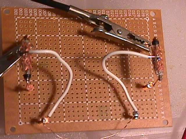
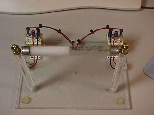
After the first series of tests a number of questions surfaced in connection with the switching of the various power supplies. Initial understanding was that a primary requirement of the circuit was that the plasma needed to be abruptly interrupted (stopped). The method shown in the Hiddink Patent(1) indicates manual switches as did additional information obtained and supplied by John Berry(2) with some of this information supposedly direct from the inventor. What became immediately evident was that it is not possible to implement this with a simple switch or relay, the reason being for want of a better description 'arc dragging'. Once you open the switch or relay contact an arc forms between the contacts and continues until the contacts are far enough apart to cause the arc to suppress, long after the cylinder power supply has fully disconnected. Now if the exact voltage used to cause a particular plasma were known and it was much less than I currently felt it was, it could indeed be possible to do with a manual switch or relay. Although in the first test series, it was not possible to rapidly switch off the plasma if over 500 volts DC was used as 'arc dragging' took place. Along this same line I was informed the inventor specified some specific tube types to be used for the plasma generation along with the type of covering to be used for the cylinder. Based upon this information, relays could be the preferred switching mechanism. Strangely enough the copper screen first used for the cylinder plate worked better than the solid copper tape over the Xenon tube. This remains an open question as the inventor has stated a solid foil can be used. The Hiddink(1) Patent shows that all voltage supply rails are removed in a simultaneous way and I found this vitally important. It is necessary in the implementation of a single plate capacitor that there be no way for a pseudo plasma or capacitive (series) path remain available for the second plate of the capacitor to continue even a minimal existence. So on to phase two: Maybe if it's not complicated it needs to be pretty. The following image is of the phase two test board. The board uses two identical relays that will switch 600 volts and they are very fast. One relay will handle the HV for the plasma and the other will control the charge voltage. I will be using a 4-watt UV tube. The tube is coated on half its surface, yet even if I can obtain 2 watts of UV I feel it should be sufficient. The relays are mounted and wired. Next some acrylic for the tube and a power pick off (the external cylinder).
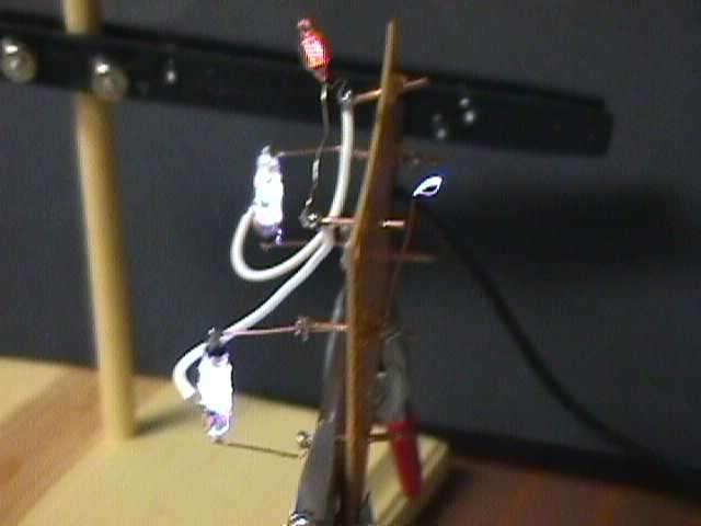
The tube supports are in place ready for the final wiring. Note that the tube supports are designed allow they testing of different covering cylinders.
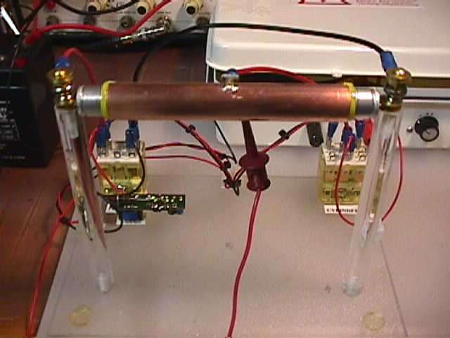
Copper cylinder around the UV tube and ready for testing. In the lover left just in front of the relay is a 450 volt transistor power supply for the UV tube. The white box in the back right is a HV supply used for charging the copper cylinder. It all was powered with a 12 volt lead acit batery rated at 8 ampere hours.
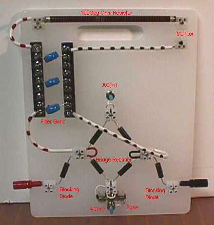
Getting ready for the large 1kJ tubes for the next set of experiments I build a new and clean power control board. It contains the bridge rectifier driven by a 12kv transformer under the control of a variac. The board has a stripp where I can add or subtract filtering, has a fuse and can be easily changed from blocking and none blocking diodes. I must limit the voltage because the diodes are good to only 12kv and the capacitors to 15kv.
Mr. Thomas (K4ZEP) was the first to come up with using the FL tube for a gainful output. The following video's are from his early work and the discovery of gain. *02/11/2010 The video's were removed by Mr. Thomas and are no longer available. Sgnificant progress in the choered energy from the optical process. http://www.youtube.com/watch?v=yUDHDzX7iOw
REFERENCES: (1) Joseph Hiddink, US
Patent #4,095,162 "Capacity Charger" (3) Mr. Ben Thomas, K4ZEP, Robotics & Electronics.
Revised: 02/11/2010
|