Copyrights(c) 2007-2010, Dr. R. R. Stiffler
Spatial Energy
Coherence
Copyrights(c) 2007-2010, Dr. R. R.
Stiffler
Electrolysis with SEC Exciters
|
Until otherwise noted the following experiments were constucted using a SEC15-3 without a parasitic plate. Using the parasitic plate reduces overall output when the Exciter is used for electrolysis. The following image shows one of the first tests made using a SEC Exciter as an electrolysis driver. The wires used in the electrodes were #26 stranded hookup wire that was of copper core and silvered plating. The cathode wires were spread out in a spider form and each leg was approximately 5mm in length. The anode wire was connected to a copper mesh. No specifications are available for this test as it was only to see if an Exciter could cause electrolysis.
There was something very interesting that was observed in the first test cell and that was a gas bubble void between the cathode and anode. All of the oxygen bubbles formed a layer over the top of the copper mesh but were not allowed to rise and escape. The hydrogen bubbles at the top acted normally although. This same void can be seem in the first image but was not noticed because of the small separation between the anode and cathode, yet a close look does make it evident.
A small stainless steel spider driven from a SEC15-3 with 20 volts supply to the exciter. Again the electrode legs were approximately 5mm in length and the wire above the spider was insulated so all the gas release is coming from the spider legs.
SEC Exciter Tuned for Electrolysis
Optimal tuning can vary, depending on which configuration of SEC Exciter is used and if any additions are made to the water used in the cell. Two particularly active spots that I have found are 13.6MHz and 10.6MHz for fp'. The above spectrum analyzer display shows the tuning of a lab exciter to an fp' of 13.6MHz at which point I obtained best gas production. The following SA picture shows an exciter tuned to 10.6HMz fp'. Notice the spectral difference and the relative amplitudes of the frequencies from 10.6MHz, the almost consistent power levels.
The SA scale is set at 10MHz per screen division.
Who says an electrolyzer can not be simple? The following circuit is a SEC Exciter driving two fine SS wires in tap water. This simple and small footprint circuit is well worth the exploration.
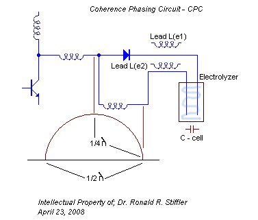
A two-fold increase in gas production can be obtained by the correct phasing of the cell electrodes. The following is a 'Coherence Phase Circuit', which is a method of phasing the excitation to the cell so that it receives maximum stimulation excitation of the surrounding energy lattice.
One artifact of the very small gas bubbles produced by a SEC Exciter is the inability for all of the bubbles to break through the surface tension of the water. This results in a high concentration of gas just under the surface and slowly migrating through it to escape into the air. This trapped gas will sustain a flame on the surface of the water, actual burning water resulting from very low power electrolysis with a wideband SEC Exciter.
One thing to keep in mind by a lay person when viewing or reading about someone burning water, is the burning rate (speed) that Hydrogen burns is in the range of (2.65-3.25 m/s) which is close to an order of magnitude above methane and gasoline. What this means is that the production rate must be very high or the flame will extinguish because the production cannot keep up with the burn rate. So if you have a slow release of gas from the water it seems that the release rate could not support a sustained burn. Now if you have a significant amount of gas trapped in the slow release portion of the cell, it still is highly questionable if a sustained burn can be produced. When looking at the flame from the device developed by 'John Kanzius{1} of Sanibel Island, Fla.', I first look at the burn rate and immediately see that it cannot be hydrogen that is burning. The flame from the 'Kanzius' device can best be described as 'slow and lazy' and a pure Hydrogen flame is extremely difficult to view in high light conditions. Yet it is very possible that the primary fuel is not Hydrogen and Hydrogen remains a small component of the actual flame.
The following table lists a number of additives I have used to increase gas production along with some specific results.
New Reactor Electrolyzer Design There are two commonly thought of ways to increase the output of a cell driven by a SEC Exciter and they are; 1) Increase the drive from the Exciter or 2) Increase the efficiency of the cell and the electrode design. The following two images are pictures of a combination of the cell structure and modification of the electrodes. This change has resulted in the output increase of some 50% with the same Exciter input. The operating cell shown in the images runs with an Exciter input of 13.6vdc at 13.5mA.
In the last of the two images the bubbler, gas collection and run off containers are seen. The burner module appears in some of the following pictures. The next image shows a standard SEC15-3 driving the reactor. The input to the Exciter is 24vdc at 22.1mA.
With a Lab or Academic SEC15-3 it is easy to pull the 22uH choke from its sockets and add the power coil (a #4 coil mounted in temporary fashion) to increase the coherence and energy into the reactor. The following picture shows a power coil added to a Lab Exciter. In addition the Exciter shown has 2 series diodes in each side of the AV Plug in order to reduce the capacity of the diodes.
Something very strange was found upon disassembly of a reactor cell (as pictured above) in that serious Stainless Steel electrode erosion was found on one of the electrodes. The following picture is of the SS bolt that was the Anode Electrode followed by a picture of the SS Nut that held the electrode in place.
More trouble found in the second reactor cell using SS rods. The rods show deep pits and gouges as shown in the following photo.
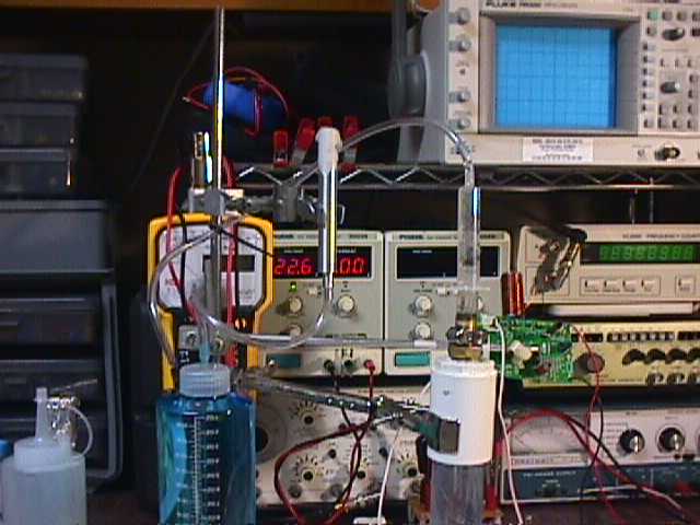
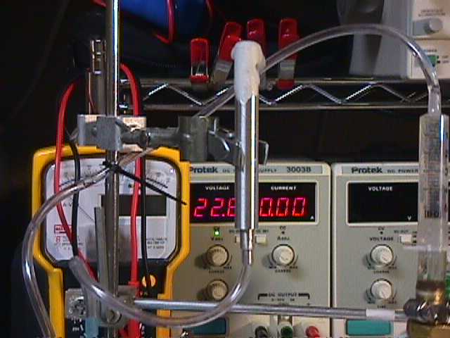
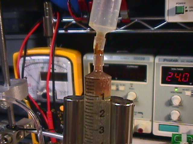
Burning the complex evolved gas can be handled in a number of different ways although I was able to use a special machined nozzle to control the release to where a controlled flame could be presented. The following two images show this burner nozzle. The following burner picture shows the power supply in the background and the gas can be seem in the syringe above the reactor, this particular test used a input voltage if 22.6v and a current of <10mA. Note that the burner is covered with a wet cotton cloth, this is used at the start of a test to slightly inhibit the flow so the burner charges and expels any trapped air.
Close up view of the burner. The burner was machined from Aluminum and has an integral flame arrestor should the H2 content increase, although the burner is connected directly to the bubbler. The purpose of the 5mL syringe at the top of the reactor serves two important purposes, it allows for a direct indication of the consumed electrolyte and provides a collection point for material expelled from within the cell (electrodes and water). This can be seen in the following picture.
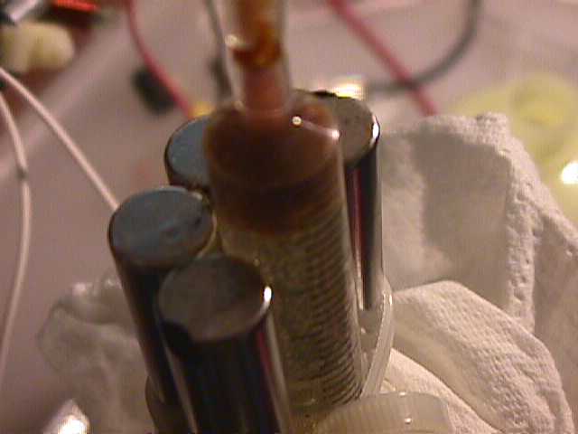
Collection of material expelled from the cell. The method found most effective is the 5mL syringe surrounded by rod magnets.
.
References: {1} John Kanzius of Sanibel Island, Fla. http://en.wikipedia.org/wiki/John_Kanzius |
Copyright (c) 2007-2008 Dr. Ronald
Stiffler. All rights reserved.
Unauthorized Copying of this material is
strictly forbidden.
Violation of these Copyrights will be
enforced.