Copyrights(c) 2008-2010, Dr. R. R. Stiffler
Spatial Energy Coherence
Copyrights(c)
2008-2010, Dr. R. R. Stiffler
SEC Exciter Circuits
|
SEC15-3
The SEC15-3 is the basic Exciter circuit from which all other Exciter variations are derived. Although there may be slight component variations in the circuit itself, the overall design concept remains the same.
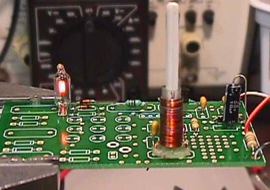
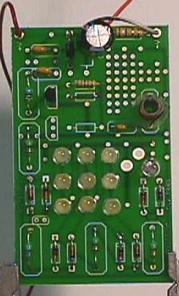
View of SEC15-3 PCB
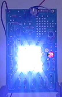
Operating SEC15-3
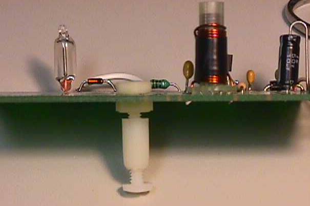
Mounting of SEC15-3 & 20's with Nylon Screw & Standoff
Modified SEC15-3 with Parasitic Plate
Layout of a modified SEC15-3
The Parasitic Plate
SEC15-3 Multipurpose
The preceding image show some of the possible loads that can be applied to a SEC15-3 Exciter. The standard Neon is shown followed by series LED chains and the electrodes of an electrolysis cell. Not shown yet viable as a load is brush less motors and incandescent light. In the case of incandescent lights the SEC-30W would be the Exciter of choice.
SEC15-20
The SEC15-20 was developed as a demonstration unit to explore various loads and the anomalies presented. While the SEC15-3 in its demonstration form drives a single Neon the SEC15-20 has nine (9) Super White LED's and at the end of the load chain a Neon. The SEC15-20 although more complex in operation is still driven by a basic exciter. The SEC15-20 is the best overall circuit to study the operation of a Spatial Exciter as it presents not only the different loads but also it is a chain linked single wire energy provider to the various loads.
View of a SEC15-20 PCB
Operating SEC15-20
SEC15-10sx
The SEC15-10sx is a special circuit in that it was designed in a similar was to the SEC15-20, except the 10sx included a muffin fan (fan motor) in the first AV Plug, followed by nine (9) Super White LED's. As with the SEC15-20 the 10sx is a circuit constructed for demonstrations and research only. The primary difference in the 10sx is that the majority of work is performed at the first AV Plug, wherein the SEC15-20 the energy is distributed along the load chain.
Generation II SEC Exciters
SEC14-1G2
The SEC14-1G2 is a SEC15-3 Generation I Exciter with an Energy Doubling Output. Here is how it works; Example: 40 Consider a single AV Plug as in the SEC15-3 and the load on that plug is one capacitor of 20uF in value and no additional loading. What I will calculate first is the energy stored in the 20uF capacitor. Assume a Vo or output voltage from the AV Plug of 135V applied across the 20uF capacitor. J = CT * (Vo ^2) / 2 = 2E-5 * (1.35E2 ^2) / 2 = 1.8225E-2 Joules This circuit is a voltage doubler and our output voltage Vo goes from 135V to; 135 * 2 = 270V We now add an additional 20uF capacitor across the newly added AV Plug as shown in the diagram. Because our capacitors are now in series our total capacity is 20 / 2 =10uF. J = CT * (Vo ^2) / 2 = 1E-5 * (2.7E2 ^2) / 2 = 3.6450E-2 Joules Each AV Plug contributes 1.8E-2 Joules
to the total of 3.6E-2 Joules in effect doubling the energy output of the
Exciter. It is to be noted that the diode(s) separating multiple stacked AV Plugs cannot be 1N4148's because these diodes cannot stand the high current that can be supplied with this configuration. I have had success with the Ultra High Frequency 1N4007's, although this diode is only rated at one (1) ampere. Why does this work? In simple terms each AV Plug is capable of providing what one single plug would. In other words if one plug can provide 1/3 Joule, then three stacked will provide 1 Joule or 3 * 1/3. The question that is always asked at this point is how many stacked plugs can be added to a single exciter? There is a limit and that limit is the minimum energy supplied by the exciter that is required to stimulate the Energy Lattice to a point that excess energy can be cohered. There is little magic in the fact that the Lattice must be excited at a minimum level before it will spontaneously return excess energy. Empirical data to date supports the following formula in predicting the energy that can be cohered. Close inspection is required to see just what exactly is the basis of the lattice excitation.
SEC14-1G1 Prototype
The Exciter on the left is a SEC15-3 modified with the parasitic plate and on the right is a three (3) stage SEC14-1G1. It does not even take mention the significant difference in Neon intensity. A three stage SEC14-1G1 is multiplying excess energy by a factor of three by utilizing three AV Plugs and voltage tripling.
|