While experimenting with these rectifiers, I have found them to work quite well and I have been able to observe the glow. It was also easy to make full wave rectifiers using more than one rectifier in traditional full wave rectifier circuits.
A rectifier can be easily made by mixing borax or baking soda into a pint jar of water and inserting an aluminum strip and a strip of another metal. After a forming process of running ac current between the two electrodes, the aluminum electrode becomes the cathode and the other electrode becomes the anode.
It seems that aluminum is necessary for the cathode, but the anode can be just about anything that conducts electricity. The aluminum cathode can be a 3/8" wide strip cut from an aluminum pie plate. The anode can be lead, carbon, steel or stainless steel. Copper tends to make a bluish green mess and does not seem as desireable. I have found most types of anode materials to work the same but the differences may be a long term effect not easily observed in the course of my experiments.
In all of my experimenting, I have found that baking soda works the same as borax. The solution can be made by either mixing 1 tablespoon of baking soda into a pint of water or by mixing Twenty Mule Team Borax into a pint of water until no more dissolves. Also, this is the first set of experiments that I have ever done with solutions conducting electricity, where the solution has not turned some yucky dark color. The solution seems to stay reasonably clear.
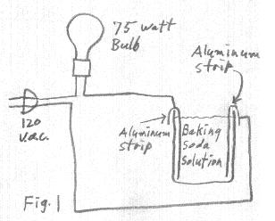
As mentioned earlier, there is a faint glow associated with these borax (or baking soda) rectifiers that can be observed in a dark room. It seems that moderately high voltages are necessary in order to produce the glow. The glow is produced on the aluminum plate when it is at the positive (reverse bias) part of the cycle and minimum current is flowing. For those who know what they are doing and are comfortable doing this kind of thing, the glow can be easily observed by connecting a 75 watt incandescent lamp in series with the rectifier and 120 vac line voltage. When first connected to the 120 vac, the lamp turns on at full brilliance. After a few minutes, the rectifier forms and the light intensity dies down to half brilliance. The lamp is now running on dc (half wave rectified). At this time the glow can be observed on the aluminum electrode if the room is sufficiently dark.
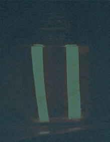
A 75 watt lamp running even at half brilliance makes it difficult to darken the room adequately. I find it easier to observe the glow by using aluminum strips for both electrodes in the jar. This creates a situation of having two rectifiers back to back, allowing very little current to flow through the lamp. When connected to power for the first time, the 75 watt lamp lights up to full brilliance. The rectifying layer then start to form on the aluminum plates until after a few minutes, the lamp brilliance dies down to nothing. At this time, both aluminum strips will be glowing.
Where the electrodes contact the top surface of the liquid, tiny flashes can sometimes be observed in addition to the glow that covers the entire electrode. This condition seems to be more prevalent with the baking soda solution than with the borax solution.
You must do any experiments connected directly to the power mains, at your own risk. I don't recomend doing this experiment unless you are familiar with the hazards that exist. There are many who question the sanity of doing experiments that are connected directly to the power mains. Granted, this creates hazards, but if precautions and common sense are used, it is less hazrdous than driving to the grocery store or being a referee at your daughters soccer game. I believe it is totally acceptable for a conscientious person with common sense to conduct, with proper precautions, experiments that are connected directly to the power mains. I will offer some suggestions however, which I do not claim to be complete.
1. Treat all parts of the circuit as though they are a red hot heating element. Only touch when you are sure the circuit is disconnected (unplugged) from the power mains.
2. Never do these experiments with bare feet.
3. Keep all parts of the circuit far enough away from metallic objects to prevent inadvertent contact with them. Use a wood or formica table.
4. Do the experiments where you are not likely to touch any metallic objects or grounded metallic objects such as water faucets, sinks, telephones etc.
5. Avoid doing experiments in wet environments.
6. Never connect experiments to other equipment unless you really know what you are doing and can absolutely assure proper isolation.
7. When making necessary adjustments to an operating circuit, always strive to do it with one hand and don't touch anything else while doing it.
8. Never leave exposed circuits that are connected to the power mains, unattended.
The oxide coating on the aluminum plate tends to form large capacitance values in parallel with the rectifier (up to many microfarads). The capacitance therefore can vary greatly, depending on how far the aluminum electrode is dipped into the solution and how long the rectifier has been forming. I have in fact, found it easy and practical to use one of these rectifier cells as a wide range variable electrolytic capacitor capable of controlling the frequency of an oscillator over a very wide range (see article on variable electrolytic capacitor).
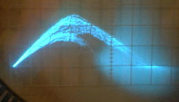
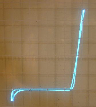
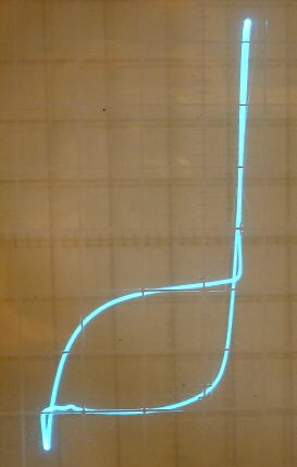
Because of this large capacitance, there seems to be an optimum plate area associated with the aluminum plate. The curve trace on the second picture above shows a capacitance loop caused by the aluminum strip immersed well into the solution. The curve trace on the first picture is flat in the reverse direction because the aluminum strip was just slightly dipped into the solution.
This opens up another very fasciniting possibility. A cell with two adjustable aluminum plates (a variable capacitor) might very well be useable as an efficient light dimmer. With varying capacitance, no power is dissipated in the cell when creating a drop in voltage being applied to the lamp. I tried using a cell with two aluminum plates as a light dimmer. By lifting both aluminum plates out of the solution simultaneously, I could dim the 75 watt lamp to any desired brightness. The only problem is that as time goes on, the plates usually continue to form, and the overall maximum capacitance eventually drops to a value too low to supply adequate current to the lamp.
The forward voltage drop of these rectifiers seems to be about 5 volts.
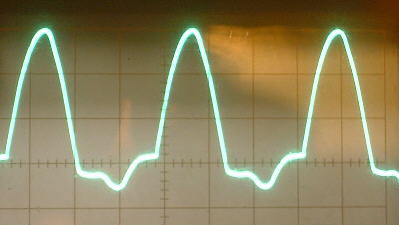
The reverse breakdown voltage of these rectifiers tends to adjust itself to a point slightly below the peak of the applied voltage. When the ac voltage is increased, this breakdown value increases accordingly. When the ac voltage is decreased, this breakdown value decreases accordingly. This can be seen in the pictures above as downward dips in left portion of the curve from the curve tracer and at the bottom of the half wave rectified waveform.
There is a bright but tiny orange glow at the point of contact but I don't believe it is the same phenomena that causes the rectifier glow because in this case, the glow happens when the aluminum is biased negative. With the rectifier, the glow is generated when the aluminum is positively biased.
This generates a lot of rf noise as the large misty area at the right part of the curve suggests. Having done just a little experimenting, I have not yet heard a real clear tone generated from this device but I can hear noise in a nearby am receiver up to the receiver's limit of 30 mhz.