Fluid Propulsion
To all whom it may concern:
Be it know that I, Nikola Tesla, and engineer residing at the Waldorf Astoria, corner Fifth Avenue and Thirty Fourth Street, in the Borough of Manhattan, City and State of New York, United States of America, having invented certain new and useful improvements in FLUID PROPULSION, do hereby declare the following is a full, clear and exact description of the same.
In the practical application of mechanical power based on the use of a fluid as vehicle of energy it has been demonstrated that, in order to attain the highest economy, the changes in velocity and direction of movement of the fluid should be as gradual as possible. In the present forms of such apparatus more or less sudden changes, shocks and vibrations are unavoidable. Besides the employment of the usual devices for imparting to vanes and blades, necessarily introduce numerous defects and limitations and adds to the complication, cost of production and maintenance of the machine.
The object of my invention is to overcome these deficiencies and to effect the transmission and transformation of mechanical energy through the agency of fluids in a more perfect manner, and by means simpler and more economical than those heretofore employed.
I accomplish this by causing the propelled or propelling fluid to move in natural paths or stream lines of least resistance, free from constraint and disturbance such as occasioned by vanes or kindred devices, and to change its velocity and direction of movement by imperceptible degrees, thus avoiding the losses due to sudden variations while the fluid is receiving or imparting energy.
` It is well know that a fluid possesses among others, two salient properties: adhesion and viscosity. Owing to these a body propelled through such a medium encounters a peculiar impediment known as "lateral" or "skin resistance", which is two-fold: one arising from the shock of the fluid against the asperities of the solid substance, the other from internal forces opposing molecular separation. As an inevitable consequence a certain amount of the fluid is dragged along by the moving body. Conversely, if the body were placed in a fluid in motion, for the same reasons, it is impelled in the direction of the movement.
These effects, in themselves, are of daily observation, but I believe that I am the first to apply them in a practical and economical matter of fluid propulsion. The nature of my discovery and the principles of construction of the apparatus, which I have designed for carrying it out, I shall now proceed to describe by reference to the accompanying drawings which illustrate an operative and efficient embodiment of the same.
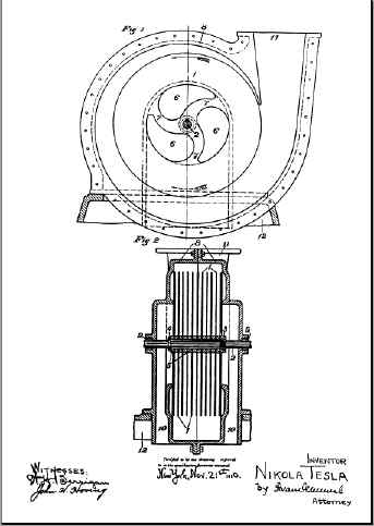
Figure 1 is a partial end view, and Figure 2 a vertical cross section of a pump or compressor, which Figures 3 and 4 represent, respectively, in corresponding views, a rotary engine or turbine, both machines being constructed and adapted to be operated in accordance with my invention.
Figures 1 and 2 show a runner composed of a plurality of flat rigid disks (1) of a suitable diameter, keyed to a shaft (2) and held in a position by a threaded nut (3), a shoulder (4) and washers (5) of the requisite thickness. Each disk has a number of central openings (6), the solid portions between which form spokes (7) preferably curved, as shown, for the purpose of reducing the loss of energy due to the impact of the fluid.
The runner is mounted in a two-part volute casing (8) having stuffing boxes (9) and inlets (10) leading to its central portion. In addition, a gradually widening and rounded outlet (11) is provided formed with a flange, for connection to a pipe as usual. The casing (8) rests upon a base (12) shown only in part and supporting the bearings for the shaft (2), which being of ordinary construction are omitted from the drawings. An understanding of the principle embodied in this device will be gained from the following description of its mode of operation.
Power being applied to the shaft and the runner set in rotation in the direction of the solid arrow, the fluid by reason of its properties of adherence and viscosity, upon entering through the inlets (10) and coming in contact with the disks (1) is taken hold of by the same and subjected to two forces, one acting tangentially in the direction of rotation, and the other radiates outward. The combined effect of the tangential and centrifugal forces is to propel the fluid with continuously increasing velocity in a spiral path until it reaches the outlet (11) from which it is ejected. This spiral movement, free and undisturbed and essentially dependent on these properties of the fluid, permitting it to adjust itself to natural paths or streamlines and to change its velocity and direction by insensible degrees, is characteristic of this method of propulsion and advantageous in its application.
While traversing the chamber enclosing the runner, the particles of the fluid may complete one or more turns, or but part of one turn. In any given case their path can be closely calculated and graphically represented, but fairly accurate estimates of turns can be obtained simply by determining the number of revolutions required to renew the fluid passing through the chamber and multiplying it by the ratio between the mean speed of the fluid and that of the disks.
I have found that the quantity of fluid propelled in this manner is, other conditions being equal, approximately proportionate to the active surface of the runner and to its effective speed. For this reason, their performance of such machines augments at an exceedingly high rate with the increase of their size and speed of revolution.
The dimensions of the device as a whole, and the spacing of the disks in any given machine will be determined by the conditions and requirements of special cases. It may be stated that the intervening distance should be the greater, the larger the diameter of the disks, the longer the spiral path of the fluid and the greater its viscosity. In general, the spacing should be such that the entire mass of the fluid, before leaving the runner, is accelerated to a nearly uniform velocity, not much below that of the periphery of the disks under normal working conditions and almost equal to it when the outlet is closed and the particles move in concentric circles.
It may also be pointed out that such a pump can be made without openings and spokes in the runner, as by using one or more solid disks, each in its own casing, in which form the machine will be eminently adapted for sewage, dredging and the like, when the water is charged with foreign bodies and spokes or vanes especially objectionable.
Another application of this principle which I have discovered to be not only feasible, buy thoroughly practicable and efficient, is the utilization of machines such as above described for the compression or rarefaction of air, or gases in general. In such cases it will be found that most of the general considerations obtaining in the case of liquids, properly interpreted, hold true.
When, irrespective of the character of the fluid, considerable pressure are desired, staging or compounding may be resorted to in the usual way, the individual runners being, preferably, mounted on the same shaft. It should be added that the same end may be attained with one single runner by suitable deflection of the fluid through rotational or stationary passages.
The principles underlying the invention are capable of embodiment also in that field of mechanical engineering which is concerned in the use of fluids as motive agents, for while in some respects the actions in the latter case are directly opposite to those met with in the propulsion of fluids, the fundamental laws applicable in the two case are the same. In other words, the operation described above is reversible, for, if water or air, under pressure, be admitted to the opening (11) the runner is set in rotation in the direction of the dotted arrow by reason of the peculiar properties of the fluid, which, traveling in a spiral path, and with continuously diminishing velocity, reaches the orifices (6 and 10) through which it is discharged. If the runner be allowed to turn freely, in nearly frictionless bearings, its rim will attain a speed closely approximating the maximum of that of the fluid in the volute channel and the spiral path of the particles will be comparatively long, consisting of many almost circular turns. If load is put on and the runner slowed down, the motion of the fluid is retarded, the turns are reduced, and the path is shortened.
(Machine dynamics: General operation)
Owing to a number of causes affecting the performance, it is difficult to frame a précis rule which would be generally applicable, but it may be stated that within certain limits, and other conditions being the same, THE TORQUE IS DIRECTLY PROPORTIONATE TO THE SQUARE OF THE VELOCITY OF THE FLUID, RELATIVELY TO THE RUNNER, AND TO THE EFFECTIVE ARE OF THE DISKS, AND, INVERSELY, TO THE DISTANCE SEPARATING THEM. THE MACHINE WILL, GENERALLY, PERFORM ITS MAXIMUM WORK WHEN THE EFFECTIVE SPEED OF THE RUNNER IS ONE HALF THAT OF THE (INCOMING) FLUID. BUT TO ATTAIN THE HIGHEST ECONOMY THE RELATIVE SPEED, OR SLIP, FOR ANY GIVEN PERFORMANCE, SHOULD BE AS SMALL AS POSSIBLE. THIS CONDITION MAY BE TO ANY DESIRED DEGREE APPROXIMATED BY INCREASING THE ACTIVE AREA AND REDUCING THE SPACE BETWEEN THE DISKS.
When apparatus of the kind described is employed for the transmission of power certain departures from similarity between transmitter and receiver may be necessary for securing the best results. I is evident that, when transmitting power from one shaft to another by such machines, any desired ratio between the speeds of rotation may be obtained by proper selection of the diameters of the disks, or, by suitably staging the transmitter, the receiver, or both. But it may be pointed out that in one respect, at least, the two machines are essentially different. In the PUMP, the radial or static pressure, due to centrifugal force, is added to the tangential or dynamic, thus increasing the effective head and assisting in the expulsion of the fluid. In the MOTOR, on the contrary, the first named pressure being opposed to that of supply REDUCES the effective head and the velocity of radial flow towards the center. Again, in the propelled machine, a great torque is always desirable, this calling for an increased number of disks and smaller distance of separation, while in the propelling machine (PUMP), for numerous economic reasons, the rotary effect should be the smallest and the speed the greatest practicable. Many other considerations, the design and construction, but the preceding is thought to contain all necessary information in this regard.
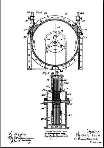
The greatest value of this invention will be found in its use for the thermo-dynamic conversion of energy. Reference is now made to Figures 3 and 4, illustrative of the manner in which it is, or may be, so applied.
As in the previous figures, a runner is provided made up of disks (13) with openings (14) and spokes (15) which, in this case may be straight. The disks are keyed to and held in position on a shaft (16), mounted to turn freely in suitable bearings, not shown, and are separated by washers (17) conforming in shape with the spokes and firmly united thereto by rivets (18). For the sake of clearness, but a few disks, with comparatively wide intervening spaces are indicated.
The runner is mounted in a casing comprising two end castings (19) with outlets (20) and stuffing boxes (21), and a central ring (22), which is bored out to a circle of a diameter slightly larger than that of the disks, and has flanged extensions (23) and inlets (24) into which finished ports, or nozzles, (25) are inserted. Circular grooves (26) and labyrinth packing (s) (27) are provided on the sides of the runner. Supply pipes (28), with valves (29), are connected to the flanged extensions of the central ring, one of the valves being, normally, closed.
With the exception of certain particulars, which will be hereinafter elucidated, the mode of operation will be understood from the preceding description. Steam or gas under pressure being allowed to pass through the valve at the side of the solid arrow, the runner is set in rotation in clockwise direction.
In order to bring out a distinctive feature assume, in the first place, that the motive medium is admitted to the disk chamber through a port, that is, a channel which it traverses with nearly uniform velocity. In this case the machine will operate as a rotary engine, the fluid continuously expanding on its tortuous path to the central outlet. The expansion takes place chiefly along the spiral path, for the spread inward is opposed by the centrifugal force due to the velocity of "whirl" and by the great resistance to the passage of the fluid between the plates (15), approximately proportionate to the square of the relative speed, which is maximum in the direction towards the center and equal to the full tangential velocity of the fluid. The path of least resistance, necessarily taken in obedience to a universal law of motion, is, virtually also that of least relative velocity.
Next. Assume that the fluid is admitted to the disk chamber no through a port, but, a DIVERGING nozzle, a device converting, wholly or in part, the expansive into velocity-energy. The machine will then work rather like a TURBINE, absorbing the energy of kinetic momentum of the particles as they "whirl", with continuously decreasing speed, to the exhaust.
The above description of operation, I may add, is suggested by EXPERIENCE AND OBSERVATION, and is advanced merely for the purpose of explanation. The undeniable fact is that the MACHINE DOES OPERATE, both expansively and impulsively. When the expansion in the nozzle is complete, or nearly so, the fluid pressure in the peripheral clearance space is small: as the nozzle is made less divergent and its section enlarged, the pressure rises, finally approximating that of the supply. But the transition from purely impulsive to expansive action may not be continuous throughout, on account of critical states and conditions and comparatively great variations of pressure may be caused by small changes of nozzle velocity.
In the preceding, it has been assumed that the pressure of supply is constant or continuous, but it will be understood that the operation will be, essentially, the same if the pressure were fluctuating or intermittent, as that due to explosions occurring in more or less rapid succession.
A very desirable feature, characteristic of machine constructed and operated in accordance with this invention, is their capability of reversal of rotation. Figure (3), while illustrative of a special case, may be regarded as typical in this respect. If the right hand valve be shut off and the fluid supplied through the second pipe, the runner is rotated in the direction of the dotted arrow, the operation, and also the performance, remaining the same as before, the central ring being bored to a circle with this purpose in view. The same result may be obtained in may other ways by specially designed valves, ports or nozzles for reversing the flow, the description of which is omitted her in the interest of simplicity and clearness. For the same reasons buy one operative port or nozzle is illustrated which might be adapted to a volute but does not fit best a circular bore. It will be understood that a number of suitable inlets may be provided around the periphery of the runner to improve the action and that the construction of the machine may be modified in many ways.
Still another valuable and probably unique quality of such motors or prime movers may be described. By proper construction and observance of working conditions, the centrifugal pressure, opposing the passage of the fluid, may, as already indicated, be made nearly equal to the pressure of supply when the machine is running idle. If the inlet section were large, small changes in the speed of revolution will produce great differences of flow, which are further enhanced by the committing variations in the length of the spiral path. A self regulating machine is thus obtained bearing a striking resemblance to a direct current electric motor in this respect that, with great difference of impressed pressure in a wide open channel, the flow of the fluid through the same is prevented by virtue of rotation. Since the centrifugal head increases as the square of the revolutions, or even more rapidly, and with modern high grade steel, great peripheral velocities are practicable, it is possible to attain that condition in a single stage machine, more readily of the runner be of large diameter. Obviously, this problem is facilitated by compounding, as will be understood by those who are skilled in the art. Irrespective of its bearing on economy, this tendency which is, to a degree, common to motors of the above description, is of special advantage in the operation of large units, as it affords a safeguard against running away and destruction.
Besides these, such a prime mover processes many other advantages, both constructive and operative. I is simple, light and compact, subject to but little wear, cheap and exceptionally easy to manufacture as small clearances and accurate milling work are not essential to good performance. In operation it is reliable, there being no valves, sliding contacts or troublesome vanes. It is almost free of windage, largely independent of nozzle efficiency and suitable for high as well as for low fluid velocities and speeds of revolution.
IT will be understood that the principles of construction and operation above generally set forth, are capable of embodiment in machines of the most widely different forms, and adapted for the greatest variety of purposes. In my present application, I have sought to describe and explain only the general and typical applications of the principle, which I believe I am the first to realize and turn to useful account.