|
|
|
|
|
Antenna
Theory
From The Radio Amateur's Handbook,
Fifty-Fifth Edition, 1978 A fundamental principle of nature is that changes in
magnetic, electric, and gravitational fields cannot propagate at infinite
velocity. In the case of ordinary circuits, the effects of this
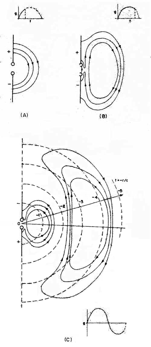
finite The manner in which energy is radiated from a circuit can be illustrated with the aid of Figs. 1 and 2. In Fig. 1, a dc voltage of 4 is applied to the upper electrode in the picture and -4 to the bottom one. Such a configuration is called a dipole although the electrodes do not have to be long thin conductors, necessarily. The actual shape is unimportant for this discussion except for the requirement of symmetry about the xy axis. The upper and lower members also have to be identical. Consequently, the field lines and equipotential contours will be symmetrical about xy. A three-dimensional view can be visualized by rotating the plot shown in Fig. I about this axis. At distances far removed from the dipole, "distortion" produced by the conductor shape becomes negligible. That is, the conductors can be considered as two point charges. The fields of a configuration of this type are well known and the strength varies as the inverse of the distance cubed. While the analysis only holds for the dc case, it is also reasonably valid for slowly varying ac voltages. However, since the intensity diminishes so rapidly with distance, such fields would not prove very useful for communication purposes. In fact, fields of this type represent energy storage similar to that of ordinary capacitors used in radio work.
If a rapidly varying ac voltage is applied to the dipole terminals, the plot illustrated in Fig. 1 is altered drastically because of the finite propagation velocity. It takes time for a change in field conditions at the dipole to reach a given point in space. The time interval is equal to the distance (between the dipole and the point) divided by the speed of light. Fig. 2 indicates how the static field is modified by this effect. Instead of building up instantaneously to the pattern of Fig. I, the field follows the moving charges on the dipole.
During the first quarter cycle, as charge builds up on the dipole, the field lines tend to spread out toward the position they would occupy under static conditions (as shown in Fig. 2A). However, during the next quarter cycle, the dipole is being discharged and some of the lines break away to form closed loops (Fig. 2B). The process repeats itself during the next two quarter cycles except that the upper half of the dipole is charged negatively. An illustration of the field plot just before a complete cycle is shown in Fig. 2C. On the other hand, if there were no delay effects, the field throughout space would follow the charge changes instantaneously. Once the source was turned off and the dipole discharged, the field would also be zero everywhere. This implies that all of the energy in the field would be returned to the dipole terminals. However, because of the time delay, "past history" is independent of present events. The effects of turning off the source could not propagate fast enough to affect variations in field that had occurred previously. Consequently, fields such as those of Fig. 2 will continue to propagate out into space in much the same manner as water waves on a pond are formed when an object that disturbs the surface is dropped in. The implication here is that energy is irretrievably lost from the dipole. This lost energy represents electromagnetic energy in the form of radiation such as radio or light waves.Radiated Power Along with the energy lost or radiated from the dipole, a certain fraction is also returned during each rf cycle. Consequently, the fields near the antenna represent both energy storage and radiation components. However, at points far enough away, the fields can be considered to belong only to the radiation component. Since it is assumed that the rf energy propagates at the same velocity in all directions, the power flowing through any imaginary sphere of a set concentric with an origin at the antenna must be the same. This is illustrated by the dashed circles in Fig. 2C. The circles represent contours of constant delay time. . . .
Radiation Resistance Considerable confusion can result if such factors as antenna gain, directivity, efficiency, size, and aperture are not regarded in their proper contests. For instance, experienced amateurs might balk at the fact that the directivity of a half-wavelength dipole is only 1.64 compared with 1.5 for a short dipole giving a difference of 0.4 dB. This would imply that a four-foot dipole on 80 meters for instance, would be just as good as a half-wave version which would correspond to approximately 135 feet! The old amateur-radio adage, "the bigger the better," in regard to antenna performance would seem to be misleading. However, another factor must be taken into account and that is the radiation resistance "seen" by the source or transmission line when connected to the antenna terminals. It will be recalled in the discussion concerning the radiation process shown in Fig. 2, energy was lost because some of the field lines broke away from the dipole and were propagated into space. In essence then, a "good" antenna configuration is one where the field extends faraway from the conductors. Considered from a slightly different point of view, antenna dimensions and associated field shape should be large at the wavelength of operation so that delay effects in the fields caused by currents on different parts of the conductors will be maximum. For instance, the parallel-plate capacitor shown in Fig. 5 would be a relatively poor radiator. Most of the field is confined between the plates and only the "fringing" field at the edge of the plates and beyond would contribute to a radiation component. (An exception would be if the dimensions of the capacitor were so large the circumference approached an appreciable fraction of a wave-length. Then, the radiation would be from the fields across the slot and the entire system would be a "dual" of an antenna made from solid conductors. This effect is often of an undesirable nature in regard to designing effective shields out of sheets that are not completely bonded or soldered together. "Leakage " of If energy will occur from the cracks.) A similar effect occurs with the so-called inverted-vee dipole. Instead of a straight dipole, the conductors are run off at an angle from the feed point. This permits the use of one high support with the ends of the antenna tied to lower supports near the ground. However, if the angle of the vee at the apex becomes too sharp, the fields tend to cancel rather than radiate.
The result of any of these effects is that the radiation resistance of the antenna becomes very low in value. This means that a high current is required to produce the same radiated power in comparison with an antenna with a higher value of radiation resistance. As a consequence, the effect of losses in such devices as matching networks, ground systems, and similar areas where currents are required to produce the radiated field become significant. A point may be reached where more power is dissipated in the losses than radiated. In cases where the losses can be neglected, the gain and directivity are the same. But while the directivity may remain the same, the antenna gain will decrease as the effect of antenna loss increases. As pointed out earlier, a small-sized antenna has the capability of being a good performer, but considerable care must be taken to insure losses do 'not offset any advantages. Also, since the ratio of energy stored to energy lost in the form of radiation (per rf cycle) is- greater in a smaller antenna compared to a larger one (at the same frequency), the bandwidth becomes smaller. The ratio of energy stored to energy lost will be recognized as being proportional to the Q of ordinary circuit theory. Hence, a small antenna represents a high-Q system and less frequency variation is permitted before retuning will be required. |
||
| Home |