
 |
|
|||||||
| Renewable Energy Discussion on various alternative energy, renewable energy, & free energy technologies. Also any discussion about the environment, global warming, and other related topics are welcome here. |
 |
| LinkBack | Thread Tools |
 Yesterday, 04:39 AM
|
|||
|
|||
|
Quote:
Very nice setup, I saw your thread in Romero's forum, and am following your progress over there. You said there is a lot of radiant energy showing up in this setup. Can you please show some scope shots of the output waveform of the gen coils? Romero's special circuit in a certain config. was giving out an AM modulated waveform, with some DC elements mixed in it. Very interesting circuits indeed, all the best to your endeavors. aaron5120           
|
|
Yesterday, 09:57 AM
|
||||
|
||||
|
Hi folks, Hi aaron5120, I checked out romeros website and oddly was thinking about a setup i wanted to try lately and there he had it in his experiments thread, well a version of it anyway.
Is it possible to register to his forum anymore. If not I'm thinking of starting a new thread here. I am seeing positive results from the solid state device using 555 timer with very low frequency and using multifilar coil with mosfet and capturing flyback into 12 volt batteries in series, while only powered by the first one in series. thanks for any information about joining his site and posting that information. peace love light tyson 
|
|
Yesterday, 10:33 AM
|
||||
|
||||
|
Quote:
great work! Please correct the schematic with the opto drivers. It was not disclosed as proved circuit! GND lines missing between drivers and FETs - source. The link to dropbox directs you to the corrected schematic - still not proved. Please insert a corresponding note! rgds John
|
|
Yesterday, 10:53 AM
|
||||
|
||||
|
Quote:
Ufo disclosed his setup with P-FET for first working replications and it does function for that task quite well. He proved it. Anyway if we intend to go for higher voltages the isolated driving seems to be mandatory or at least strongly recommended. (My opinion) Please understand that for current stage of replication it is not one single way and don't jump to high end directly! 1. Replicate with bottem side FET first 2. Replicate with bottom and top FET a) P-FET / N- FET alternatively b) N-FET only with optical isolation. 3. More to come rgds John
|
|
Yesterday, 11:01 AM
|
||||
|
||||
|
Quote:
 . . Just now I have no explanation for the behaviour reported except the BC547/557 are much faster and have more current amplification - perhaps the problem is overdriving ?????? rgds John
|
|
Yesterday, 11:08 AM
|
|||
|
|||
|
noted
Quote:
i'm unable to locate any corrected schematic so far but will insert it as soon as its located. would anyone host the pdf and post a link here so non-registered readers may also access the pdf?  rev 1.1 attached
|
|
Yesterday, 02:49 PM
|
||||
|
||||
|
1st July 2012 Experiments
Hey Group,
I took a few weeks off experimenting as had little time and needed the break to just research  Last night I made a new 555 PWM ciruit + coil with #18 wire x2, 150 ft each and measures 1.1 Ohms. Weight is >600 grams and seems to have more potential  than the #23 previously utilized in last 4-5 coils. than the #23 previously utilized in last 4-5 coils.I uploaded 10 pics from last nights experiments and will be easier to upload just a link to my folder and save space  Radiant Anomalies pictures by ZeropointEnergy - Photobucket Regards Zero 
|
|
Yesterday, 03:32 PM
|
||||
|
||||
|
Best Anomaly
Hey Group,
This was my favourite anomaly from the 1st July 2012 experiments. 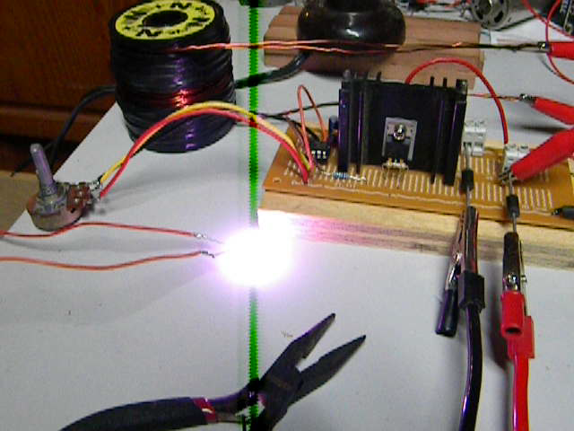 This is the 555 based PWM circuit from my YouTube clips with the only changes, the new coil and the larger NTE576 diodes in place of the 200mA NTE diodes due to the larger ones will not fit the test board 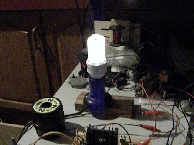 The one you want to see Ufo. A 240V@10W CFLRegards Zero
|
|
Yesterday, 04:27 PM
|
|||
|
|||
|
John Stone
Hello Sir
Sorry for the confusion on my part. I am sticking to you setup and testing. The thing that confused me was this "I am convinced that our circuit with two FETs (up and down) can do with P-FET on high side only. This is because a P-FET get its voltage reference from the battery and this is stable at any condition. At same time P_FETs have their source leg at battery voltage as well. As member Ufo proved this is true because he owns a working setup." I thought that you were thinking in favor of p-fets after reading that statement and was trying to understand why. You are vary advansed in this stuff and I always yield to persons who do know there stuff. I now see that you were talking about UFO's circuit and not your own. Carry on.  @zeropointenergy Great pictures and I see you are comming along well. Good Work. Dana  Last edited by prochiro : Yesterday at 04:30 PM.
|
|
Yesterday, 08:55 PM
|
|||
|
|||
|
Some initial CF testing.
UFO et al,
I have attempted to attach a pdf. to this post. I have done some testing to try to determine what coil arrangement to use with the CF. All measurements of Output are from the CF Secondary coil only (not the main Output of the system). The most volts that I have been able to get is around 140v, but i think this may be just half of the output as I can only measure it by placing two diodes to direct it one direction. Also, all my measurements are in parallel to an NE-2 and spark gap bulb that are lit. I guess this may take away from the output too and give lower measurements. (?) So far the best uses a mere 12' of 2" CF tape (50k unidirectional fibers). The copper magnet wire coil over it is still in question, but so far 4 strands in parallel of 380' of 19AWG work and are around 1 ohm. If "she" is strongest immediately at the edge of the magnet wire coil, might it be a good idea to wind the magnet wire and the CF in a modified bi-filar fashion so that the CF is right with the magnet wire all the way through? I found a small 13w CFL by Sylvania that says INSTANT ON and it lights easier than others for low power testing. I have been using it on 24v. The "huge" Neon that I have is a NE-30 and is made to run on 120v and fits the common 120 Edison socket. It lights on 24v in my current 2 MOSFET UFO Device with as low as 40mA and seems to not mind 4-5A either. I put it in a 120 lamp to see what is normal for it and it's not much brighter there than in my most recent Photobucket pic. I have been using it as a power level indicator/Output load during my testing. BTW, if you're going to hold both Output leads of put your hands in water with them, keep the Frequency high. Low Frequency means that whatever Duty Cycle you have going is going to be on longer time-wise and deliver a "more profound" sensation to your body. In other words, if you're using a 20% Duty Cycle, 20% of 10Hz is .02 seconds long while 20% of 100Hz is only .002 seconds (a 10th of the time). The higher Frequency feels less hammering. Enjoy, Bob
|
|
Yesterday, 09:03 PM
|
||||
|
||||
|
[quote=s e t h;200156]
i'm unable to locate any corrected schematic so far but will insert it as soon as its located.../QUOTE] Hi seth, here is the link for the corrected schematic with opto drive: still preliminary and still under construction = not proved.
|
|
Yesterday, 10:25 PM
|
||||
|
||||
|
JohnStone
Hi John
I find it interesting in your circuit... regarding the output of the driver circuit to the FET gate. Since the FET is a voltage driven device, I think you need a resistor to ground several magnitudes higher than the 10Ohm current limiting resistor to translate the current to voltage for the gate. You also don't have bypass diodes to protect your FETs. Regards Larry Last edited by larryross : Yesterday at 10:27 PM.
|
|
||||
|
Hello to All
Hello to all!!
@Seth: Thanks so much for creating such a great pdf, great work! And very organized, I will be giving you some info on some components later on, like the NTE576 is cross referenced to the UF505 which is a more "international" number...Thanks! @John Stone: Great work there !!, And agree 200% that Opto-Isolators is the only way to go to handle higher V on future circuits, yours looks excellent!! Yes I do have a working P-N Channel oscillator, I have described here many times, it is based on same 555 timer original, and I just extended a second 555 (IC2) as an inverted signal (mirror), I used same exact power feeding from first IC1, and adjustments are done by "Master" IC1, I just attached Leg 3 from IC1 (Still going to N-Channels 100 Ohms-330 TO Gates of N-Channels) but connected to Leg 2 (trigger) of IC2, then IC2 drive the P-Channel Fet's, same 100-330 ohms, EXCEPT Gate Bias goes to POSITIVE by a 4.7 K resistor on each P-Fet. I will supply a diag soon, but I posted before where I got it from...but now am working still on Motors...and Asymm. My recommendation to starters: Please try first the plain "Jame" 555 cheaper ways with N-Channels, and actually be very honest here, the P-Fet's are NOT as strong to drive High Impact Coils, and as a matter of fact, I have Not been able to find a perfect match for the NTE2397...and the "Ideal Oscillator of this types should be a "Factory almost identical Spec's but as different transistors (something similar to Audio Amps Matches, so you guys have an idea)...This brings some problems at low frequencies pulsing, they do not pulse exactly equally...P-Fet's take longer to reach synchrony to N-Channels, but what happens is they start at zero resistance til they start increasing resistance to Mega-ohms between Source-Gate...I really do not have the time right now to fix that issue, maybe biasing gates more idk...but it works ok so far, and for heavy motor pulse (and so I recommend on very low resistance Coils, N-Channels, strong Fet's)... I use the N-Channels. Now get ready for what is "Coming soon to a Theater near you...", Hold Your Panties and Socks real tight... Regards and Good bye to all. @ZPE: Great and impressive Neon lighting there!! WOW!!...You are "Full Blasting it!! @Bob French: Great and patient work with the CF Bob!! Congratulations!!excellent results, @Bob and ZPE: The LADY is "captivating" isn't SHE? Prochiro: great work, just like your friend Bob!! excellent! @Larry: Get ready to build and install an "Endless Running Time Motor" on your R/C Planes...I highly recommend to install one of those "Air Range Alarm" circuits so you don't loose it in case a returning servo Aileron will malfunction... Regards to all, and I'll see you all on the 4th... Ufopolitics
|
|
| Thread Tools | |
|
|


