Energetic Forum  

Go Back   Energetic Forum > Energetic Forum Discussion > Renewable Energy
Welcome, lamare.
You last visited: Today at 06:30 PM
Private Messages: Unread 2, Total 30.
Homepage Energetic Science Ministries User CP FAQ Calendar Search New Posts Mark Forums Read Open Buddy List Log Out

Renewable Energy Discussion on various alternative energy, renewable energy, & free energy technologies. Also any discussion about the environment, global warming, and other related topics are welcome here.

Reply
 
LinkBack Thread Tools Search this Thread Rating: Thread Rating: 9 votes, 4.89 average.
  #1231 (permalink)   Report Post  
Old 07-10-2012, 06:22 PM
wingstalysis's Avatar
wingstalysis wingstalysis is offline
Junior Member
 
Join Date: Mar 2012
Posts: 19
Cool Brushed DC Motor

Greetings,
Most of you are way ahead of this, but for the beginner with shallow pockets like me. I have been experimenting with some success using the following motors connected shaft to shaft. They are used in Black and Decker cordless drills. They can be purchased from t-swifty on ebay. He also gives a data sheet, which also you can get from the Johnson motor website easily. This is an inexpensive way to start experimenting. Hope this helps your pocket, and your experiments. Take it easy, and stay frosty.
Johnson 600 size Model Boat Electric Motor 6-12v | eBay:Johnson 600 size Model Boat Electric Motor 6-12v | eBay

For shaft connector: UNIVERSAL MODEL BOAT COUPLING ( 3.2mm Plain - Various Sizes ) | eBay
__________________
__________________
I AM THE ONE

Last edited by wingstalysis : 07-10-2012 at 06:26 PM. Reason: motor web address missing
Digg this Post!Add Post to del.icio.usBookmark Post in TechnoratiFurl this Post!Live Bookmark this Post!Google Bookmark this Post!Yahoo Bookmark this Post! share on MyspaceShare on FacebookTweet this thread
Reply With Quote Multi-Quote This Message Quick reply to this message
  #1232 (permalink)   Report Post  
Old 07-10-2012, 08:06 PM
larryross's Avatar
larryross larryross is online now
Senior Member
 
Join Date: May 2012
Location: In my shop
Posts: 137
Send a message via Skype™ to larryross
Quote:
Originally Posted by john_g View Post
Hi John

You can buy it from RS in the UK, I asked them yesterday if they did bare copper, and this is what they offered - a coincidence! However it is not insulated.

Buy Hookup & Equipment Wire Tinned annealed copper wire,24swg 91.3m RS 1288P online from RS for next day delivery.
Plus this which is insulated:
Buy Hookup & Equipment Wire 1.0mm Panel Wire UL-CSA-HAR 1015 Brown Lapp 4160303 online from RS for next day delivery.

Regards

John
John
Put on your thinking cap... I would like to read about the tinned copper wire.

Regards
Larry
Digg this Post!Add Post to del.icio.usBookmark Post in TechnoratiFurl this Post!Live Bookmark this Post!Google Bookmark this Post!Yahoo Bookmark this Post! share on MyspaceShare on FacebookTweet this thread
Reply With Quote Multi-Quote This Message Quick reply to this message
  #1233 (permalink)   Report Post  
Old 07-10-2012, 08:07 PM
JohnStone's Avatar
JohnStone JohnStone is online now
Senior Member
 
Join Date: Feb 2009
Posts: 426
Thanks! What a coincidence! The manufacturer is "LAPP Kabel" in Germany. This was a former supplyer for my company! Thanks again!
__________________
Experts spend hours a day in order to question their doing while others stopped thinking feeling they were professionals.

Last edited by JohnStone : 07-10-2012 at 08:09 PM.
Digg this Post!Add Post to del.icio.usBookmark Post in TechnoratiFurl this Post!Live Bookmark this Post!Google Bookmark this Post!Yahoo Bookmark this Post! share on MyspaceShare on FacebookTweet this thread
Reply With Quote Multi-Quote This Message Quick reply to this message
  #1234 (permalink)   Report Post  
Old 07-10-2012, 08:43 PM
larryross's Avatar
larryross larryross is online now
Senior Member
 
Join Date: May 2012
Location: In my shop
Posts: 137
Send a message via Skype™ to larryross
All
Here is some tinned insulated wire at reasonable price.

Solid Hookup Wire (300 Volt) UL 1007/1569

Larry
Digg this Post!Add Post to del.icio.usBookmark Post in TechnoratiFurl this Post!Live Bookmark this Post!Google Bookmark this Post!Yahoo Bookmark this Post! share on MyspaceShare on FacebookTweet this thread
Reply With Quote Multi-Quote This Message Quick reply to this message
  #1235 (permalink)   Report Post  
Old 07-10-2012, 08:52 PM
JohnStone's Avatar
JohnStone JohnStone is online now
Senior Member
 
Join Date: Feb 2009
Posts: 426
Quote:
Originally Posted by larryross View Post
John
Put on your thinking cap... I would like to read about the tinned copper wire.
Regards
Larry
BTW: the hint regarding tinned wire is here
In the book "Manual of Free Energy Devices and Systems" by D.A. Kelly (1991), Electrodyne Corporation reports that Tinned Copper Wire produces a 3x improvement in magnetic field strength when used in Newman coils, over regular copper wire.
Link to the ebook mentioned above

I do not want to distract from our goal. It is just a hint to consider the type of wire or other minute differences.

i.e. oxydized copper is a semiconductor and thre is a patent out there stating that coils manufactured out of semiconductor covered wire emit OU effects. So a poor guy from Africa might have success using a corroded wire from scrap while we are confused using brand new shiny wires.
__________________
Experts spend hours a day in order to question their doing while others stopped thinking feeling they were professionals.
Digg this Post!Add Post to del.icio.usBookmark Post in TechnoratiFurl this Post!Live Bookmark this Post!Google Bookmark this Post!Yahoo Bookmark this Post! share on MyspaceShare on FacebookTweet this thread
Reply With Quote Multi-Quote This Message Quick reply to this message
  #1236 (permalink)   Report Post  
Old 07-10-2012, 09:02 PM
larryross's Avatar
larryross larryross is online now
Senior Member
 
Join Date: May 2012
Location: In my shop
Posts: 137
Send a message via Skype™ to larryross
All
If you have holes in your knowledge about inductive kick watch this tut... best explanation I've seen. The solution circuit is like our circuit except we have 2 diodes and his is a complete circuit through the diode so maybe the problem is in not having anything hooked across the 2 diodes. With one coil you have the FET blower circuit and with 2 coils you have the FET protector. When not using the second coil, connect the 2 lose ends of the diodes together.

Inductive spiking tutorial - YouTube

Hope this helps
Larry
Digg this Post!Add Post to del.icio.usBookmark Post in TechnoratiFurl this Post!Live Bookmark this Post!Google Bookmark this Post!Yahoo Bookmark this Post! share on MyspaceShare on FacebookTweet this thread
Reply With Quote Multi-Quote This Message Quick reply to this message
  #1237 (permalink)   Report Post  
Old 07-10-2012, 09:25 PM
larryross's Avatar
larryross larryross is online now
Senior Member
 
Join Date: May 2012
Location: In my shop
Posts: 137
Send a message via Skype™ to larryross
our circuit simplified.

Digg this Post!Add Post to del.icio.usBookmark Post in TechnoratiFurl this Post!Live Bookmark this Post!Google Bookmark this Post!Yahoo Bookmark this Post! share on MyspaceShare on FacebookTweet this thread
Reply With Quote Multi-Quote This Message Quick reply to this message
  #1238 (permalink)   Report Post  
Old 07-10-2012, 11:17 PM
larryross's Avatar
larryross larryross is online now
Senior Member
 
Join Date: May 2012
Location: In my shop
Posts: 137
Send a message via Skype™ to larryross
Hi Ian
Here is some thing that might interest you.

Oscilloscope Tutorial Part 1 - Choosing an oscilloscope - YouTube

Regards
Larry
Digg this Post!Add Post to del.icio.usBookmark Post in TechnoratiFurl this Post!Live Bookmark this Post!Google Bookmark this Post!Yahoo Bookmark this Post! share on MyspaceShare on FacebookTweet this thread
Reply With Quote Multi-Quote This Message Quick reply to this message
  #1239 (permalink)   Report Post  
Old 07-11-2012, 02:39 AM
larryross's Avatar
larryross larryross is online now
Senior Member
 
Join Date: May 2012
Location: In my shop
Posts: 137
Send a message via Skype™ to larryross
Quote:
Originally Posted by JohnStone View Post
BTW: the hint regarding tinned wire is here
In the book "Manual of Free Energy Devices and Systems" by D.A. Kelly (1991), Electrodyne Corporation reports that Tinned Copper Wire produces a 3x improvement in magnetic field strength when used in Newman coils, over regular copper wire.
Link to the ebook mentioned above

I do not want to distract from our goal. It is just a hint to consider the type of wire or other minute differences.

i.e. oxydized copper is a semiconductor and thre is a patent out there stating that coils manufactured out of semiconductor covered wire emit OU effects. So a poor guy from Africa might have success using a corroded wire from scrap while we are confused using brand new shiny wires.
Thanks John
Great read. Looks like an interesting project.

Larry
Digg this Post!Add Post to del.icio.usBookmark Post in TechnoratiFurl this Post!Live Bookmark this Post!Google Bookmark this Post!Yahoo Bookmark this Post! share on MyspaceShare on FacebookTweet this thread
Reply With Quote Multi-Quote This Message Quick reply to this message
  #1240 (permalink)   Report Post  
Old 07-11-2012, 04:30 AM
Ufopolitics's Avatar
Ufopolitics Ufopolitics is online now
Senior Member
 
Join Date: Feb 2012
Location: US, Florida
Posts: 600
Asymmetry To Enlightenment

ASYMMETRY TO ENLIGHTENMENT - YouTube
Digg this Post!Add Post to del.icio.usBookmark Post in TechnoratiFurl this Post!Live Bookmark this Post!Google Bookmark this Post!Yahoo Bookmark this Post! share on MyspaceShare on FacebookTweet this thread
Reply With Quote Multi-Quote This Message Quick reply to this message
  #1241 (permalink)   Report Post  
Old 07-11-2012, 04:58 AM
bbem bbem is offline
Member
 
Join Date: Sep 2011
Posts: 78
Ufo

Congratulations with this masterpiece
Nice 'present' for dr.Tesla, and our world.
Very well explained and beautifull pictures, chapeau.
Need to review again to digest it.

Bert

Last edited by bbem : 07-11-2012 at 05:00 AM.
Digg this Post!Add Post to del.icio.usBookmark Post in TechnoratiFurl this Post!Live Bookmark this Post!Google Bookmark this Post!Yahoo Bookmark this Post! share on MyspaceShare on FacebookTweet this thread
Reply With Quote Multi-Quote This Message Quick reply to this message
  #1242 (permalink)   Report Post  
Old 07-11-2012, 06:10 AM
Les_K Les_K is online now
Senior Member
 
Join Date: Dec 2010
Posts: 180
Yeah, Tesla!

....NICE!...

Happy birthday to the world!


Les
Digg this Post!Add Post to del.icio.usBookmark Post in TechnoratiFurl this Post!Live Bookmark this Post!Google Bookmark this Post!Yahoo Bookmark this Post! share on MyspaceShare on FacebookTweet this thread
Reply With Quote Multi-Quote This Message Quick reply to this message
  #1243 (permalink)   Report Post  
Old 07-11-2012, 06:24 AM
mikec_ut mikec_ut is online now
Junior Member
 
Join Date: Sep 2011
Posts: 3
I am so ready

I have my two motors, can't wait. Great video. This is going to be fun.
Digg this Post!Add Post to del.icio.usBookmark Post in TechnoratiFurl this Post!Live Bookmark this Post!Google Bookmark this Post!Yahoo Bookmark this Post! share on MyspaceShare on FacebookTweet this thread
Reply With Quote Multi-Quote This Message Quick reply to this message
  #1244 (permalink)   Report Post  
Old 07-11-2012, 08:39 AM
john_g john_g is online now
Senior Member
 
Join Date: Jul 2008
Posts: 334
UFOpolitics

Fantastic video - thank you. I can see why it took so long to make.
Look forward to trying to replicate.

Regards
John
Digg this Post!Add Post to del.icio.usBookmark Post in TechnoratiFurl this Post!Live Bookmark this Post!Google Bookmark this Post!Yahoo Bookmark this Post! share on MyspaceShare on FacebookTweet this thread
Reply With Quote Multi-Quote This Message Quick reply to this message
  #1245 (permalink)   Report Post  
Old 07-11-2012, 10:55 AM
anthonynoahan anthonynoahan is offline
Junior Member
 
Join Date: Jul 2012
Posts: 1
I had gone through the post. The motors which I am using was good as I was using them from many years and doesn't came across any problem with them. Could you please produce some attachment links regarding the book that you have described. I am having the motor from the manufacturers amperis.


partial discharge detector
winding resistance meter
Digg this Post!Add Post to del.icio.usBookmark Post in TechnoratiFurl this Post!Live Bookmark this Post!Google Bookmark this Post!Yahoo Bookmark this Post! share on MyspaceShare on FacebookTweet this thread
Reply With Quote Multi-Quote This Message Quick reply to this message
  #1246 (permalink)   Report Post  
Old 07-11-2012, 03:57 PM
larryross's Avatar
larryross larryross is online now
Senior Member
 
Join Date: May 2012
Location: In my shop
Posts: 137
Send a message via Skype™ to larryross
Quote:
Originally Posted by Ufopolitics View Post
UFO
How can I email you? I would rather not discuss my comments about your video on the forum.

Regards
Larry
Digg this Post!Add Post to del.icio.usBookmark Post in TechnoratiFurl this Post!Live Bookmark this Post!Google Bookmark this Post!Yahoo Bookmark this Post! share on MyspaceShare on FacebookTweet this thread
Reply With Quote Multi-Quote This Message Quick reply to this message
  #1247 (permalink)   Report Post  
Old 07-11-2012, 04:38 PM
prochiro prochiro is online now
Member
 
Join Date: Jun 2011
Posts: 80
Posts

Larry
Click on his title name at the top of the post and select private email.
Dana

By the way, Thankyou for the help given in your posts.
Digg this Post!Add Post to del.icio.usBookmark Post in TechnoratiFurl this Post!Live Bookmark this Post!Google Bookmark this Post!Yahoo Bookmark this Post! share on MyspaceShare on FacebookTweet this thread
Reply With Quote Multi-Quote This Message Quick reply to this message
  #1248 (permalink)   Report Post  
Old 07-11-2012, 04:59 PM
IndianaBoys's Avatar
IndianaBoys IndianaBoys is online now
Senior Member
 
Join Date: Aug 2008
Posts: 313
Quote:
Originally Posted by anthonynoahan View Post
I had gone through the post. The motors which I am using was good as I was using them from many years and doesn't came across any problem with them. Could you please produce some attachment links regarding the book that you have described. I am having the motor from the manufacturers amperis.


partial discharge detector
winding resistance meter
Anthonynoahan,

That is great you posted this. The price for the Switchgear ULD 40 in US Dollars is around $3,350.
Switchgear ULD 40 | Amperis - Tests & measurement electrical instruments

Found a similar one made by Amprobe at Allied Electric for $350 USD:

Amprobe ULD-300
Amprobe - ULD-300 - Testers - Ultrasonic - Allied Electronics

While locating corona arcs with a camera that cost over $100,000 and rent for $18,000 for 3 months (price keeps it out of reach for most), the above test devices put detecting the corona arcs at a level more can afford.

These devices will also help break "The Spell" as UFOPolitics puts it.

Below is a visual of corona discharge. While they are looking at ways to eliminate it, we are looking at ways to set up the environment to direct it, manage it, and put it into positive beneficial uses.

Eliminating Corona: Using Epsilon Midsun RTV HVIC for eliminating Corona Discharge
Eliminating Corona: Using Epsilon Midsun RTV HVIC for eliminating Corona Discharge - YouTube

IndianaBoys
Digg this Post!Add Post to del.icio.usBookmark Post in TechnoratiFurl this Post!Live Bookmark this Post!Google Bookmark this Post!Yahoo Bookmark this Post! share on MyspaceShare on FacebookTweet this thread
Reply With Quote Multi-Quote This Message Quick reply to this message
  #1249 (permalink)   Report Post  
Old 07-11-2012, 05:16 PM
Ufopolitics's Avatar
Ufopolitics Ufopolitics is online now
Senior Member
 
Join Date: Feb 2012
Location: US, Florida
Posts: 600
Hello Larry

Quote:
Originally Posted by larryross View Post
UFO
How can I email you? I would rather not discuss my comments about your video on the forum.

Regards
Larry
Hello Larry,

Is there something wrong?...did you like it?...

ufopolitics@gmail.com

regards

Ufopolitics
Digg this Post!Add Post to del.icio.usBookmark Post in TechnoratiFurl this Post!Live Bookmark this Post!Google Bookmark this Post!Yahoo Bookmark this Post! share on MyspaceShare on FacebookTweet this thread
Reply With Quote Multi-Quote This Message Quick reply to this message
  #1250 (permalink)   Report Post  
Old 07-11-2012, 08:32 PM
Les_K Les_K is online now
Senior Member
 
Join Date: Dec 2010
Posts: 180
Understandings...

Ok, I have been looking at this incredible work. I understand this at the basic level. The collapse of the magnetic field is creating the high voltage spike and that is being sent to be used/captured just like the Bedini SSG or window motor etc. That all makes sense to me.

The interesting thing that I see in the video is your point about the flow and more than one coil. These streams are not running against each other(Thank you! ) But are in a flow interlaced. If I were to guess, I would say we are looking at something like a DNA strand as it winds around the center while spinning.

I am not sure I can see how to implement this in the radio shack motors. At first I thought maybe We were going to remove the brushes etc. from one and add to the back side of the other. but that is not easily done with these motors.

Anyway If I understand this right This is splitting the streams which I understand to be the "Secret"..... Is that fundamentally why two coils?

One other thing that it looks like it can do is be either a generator or motor?
This is going to require a lot of thinking but it is starting to clear some of the fog... But I can't wait to see my little motors here spinning just like what is shown. Replication is everything....


Les
Digg this Post!Add Post to del.icio.usBookmark Post in TechnoratiFurl this Post!Live Bookmark this Post!Google Bookmark this Post!Yahoo Bookmark this Post! share on MyspaceShare on FacebookTweet this thread
Reply With Quote Multi-Quote This Message Quick reply to this message
  #1251 (permalink)   Report Post  
Old 07-12-2012, 01:05 AM
iankoglin's Avatar
iankoglin iankoglin is online now
Senior Member
 
Join Date: Mar 2009
Posts: 105
Re Kogs 555 Oscillator

[quote=Ufopolitics;180157]Hello
Quote:
Originally Posted by kapierenundkopieren View Post
!!

Yesssss!!!!! Now, That work looks AWESOME!!!

Yes, that is perfect, I knew at least ONE of You guys will give the final touches at great detail.!!!

That is wonderful!!

Ufopolitics
G'Day UFO, kapierenundkopieren,EtAl
I am still having trouble I am sure it is the 555 Timer circuit I have ordered an Oscillator from China This one here
eBay Australia: Buy new & used fashion, electronics & home d�r

While I am waiting for it to come I still need to understand why this one I have tried to replicate does not work

First of all It does seem to Oscillate, as when I Connect to the DMM set in duty cycle mode as I turn the pot from lowest about 1.4%? gradually increases to highest 99%? But when connected to the Mosfet circuit it does not turn the mosfets on.
The volts at the output to the Gate bus on the Mosfet circuit is only about 2,5V? and this showed to be about right when I measured with the Scope
Question
When the 555 circuit is Oscillating and the input is 12v is not the output to the Gate bus expected to be 12v the same as the input 12v but switching at the pulse rate of the duty cycle?
Also
Should the frequency remain reasonably the same throughout the changing of the duty cycle?

IN UFO's Circuit /Diagram My Motors got me to Tap into Radiant Energy
the Wiper to the 250k pot comes from pin7 by passing the diodes before D4 (in kapierenundkopieren's it is D2) where as the wiper in kapierenundkopieren's Post here
My Motors got me to Tap into Radiant Energy
comes from pin 6 before Diode His D1(which is D5 in UFO's)

I have mine set up as per UFO's
Please
Which is the correct setup?
What would stop/reduce the output volts?

Regards

Still
Digg this Post!Add Post to del.icio.usBookmark Post in TechnoratiFurl this Post!Live Bookmark this Post!Google Bookmark this Post!Yahoo Bookmark this Post! share on MyspaceShare on FacebookTweet this thread
Reply With Quote Multi-Quote This Message Quick reply to this message
  #1252 (permalink)   Report Post  
Old 07-12-2012, 01:34 AM
Ufopolitics's Avatar
Ufopolitics Ufopolitics is online now
Senior Member
 
Join Date: Feb 2012
Location: US, Florida
Posts: 600
You will see them...

Quote:
Originally Posted by Les_K View Post
Ok, I have been looking at this incredible work. I understand this at the basic level. The collapse of the magnetic field is creating the high voltage spike and that is being sent to be used/captured just like the Bedini SSG or window motor etc. That all makes sense to me.

The interesting thing that I see in the video is your point about the flow and more than one coil. These streams are not running against each other(Thank you! ) But are in a flow interlaced. If I were to guess, I would say we are looking at something like a DNA strand as it winds around the center while spinning.

I am not sure I can see how to implement this in the radio shack motors. At first I thought maybe We were going to remove the brushes etc. from one and add to the back side of the other. but that is not easily done with these motors.

Anyway If I understand this right This is splitting the streams which I understand to be the "Secret"..... Is that fundamentally why two coils?

One other thing that it looks like it can do is be either a generator or motor?
This is going to require a lot of thinking but it is starting to clear some of the fog... But I can't wait to see my little motors here spinning just like what is shown. Replication is everything....


Les
Hello Les, Thanks and yes...you will see them...

Regards


Ufopolitics
Digg this Post!Add Post to del.icio.usBookmark Post in TechnoratiFurl this Post!Live Bookmark this Post!Google Bookmark this Post!Yahoo Bookmark this Post! share on MyspaceShare on FacebookTweet this thread
Reply With Quote Multi-Quote This Message Quick reply to this message
  #1253 (permalink)   Report Post  
Old 07-12-2012, 02:07 AM
prochiro prochiro is online now
Member
 
Join Date: Jun 2011
Posts: 80
[quote=iankoglin;201290]
Quote:
Originally Posted by Ufopolitics View Post
Hello

G'Day UFO, kapierenundkopieren,EtAl
I am still having trouble I am sure it is the 555 Timer circuit I have ordered an Oscillator from China This one here
eBay Australia: Buy new & used fashion, electronics & home d�r

While I am waiting for it to come I still need to understand why this one I have tried to replicate does not work

First of all It does seem to Oscillate, as when I Connect to the DMM set in duty cycle mode as I turn the pot from lowest about 1.4%? gradually increases to highest 99%? But when connected to the Mosfet circuit it does not turn the mosfets on.
The volts at the output to the Gate bus on the Mosfet circuit is only about 2,5V? and this showed to be about right when I measured with the Scope
Question
When the 555 circuit is Oscillating and the input is 12v is not the output to the Gate bus expected to be 12v the same as the input 12v but switching at the pulse rate of the duty cycle?
Also
Should the frequency remain reasonably the same throughout the changing of the duty cycle?

IN UFO's Circuit /Diagram My Motors got me to Tap into Radiant Energy
the Wiper to the 250k pot comes from pin7 by passing the diodes before D4 (in kapierenundkopieren's it is D2) where as the wiper in kapierenundkopieren's Post here
My Motors got me to Tap into Radiant Energy
comes from pin 6 before Diode His D1(which is D5 in UFO's)

I have mine set up as per UFO's
Please
Which is the correct setup?
What would stop/reduce the output volts?

Regards

Still
Kogs
This may be as stupid question but I have been watching you struggle for some time. First, if you have 2.5 volts to the gate, that part should work. Just in case, you could take a fet and do a test rig with a variable power supple to check when yours will fire. All could be low voltage and a LED/resistor setup.
You should also have 12 volts or so at the source pins. This is not enough to lite the cfl but good for testing. If you have 2.5v at gate and 12v at source and 0v at drain, then fets are blown. Otherwise, there is no reason for them not to work. If you are using the cfl to tell if the fet is fireing, not a good method as with all working at 12 volts only it would be hard to get cfl to go the first time without exact timing. If you think that there is no fet on time, check the gate to gound voltage and see, if you have not done so already. Just trying to help. I think that you getting the PWM will solve everything fast.
Dana
Digg this Post!Add Post to del.icio.usBookmark Post in TechnoratiFurl this Post!Live Bookmark this Post!Google Bookmark this Post!Yahoo Bookmark this Post! share on MyspaceShare on FacebookTweet this thread
Reply With Quote Multi-Quote This Message Quick reply to this message
  #1254 (permalink)   Report Post  
Old 07-12-2012, 02:33 AM
iankoglin's Avatar
iankoglin iankoglin is online now
Senior Member
 
Join Date: Mar 2009
Posts: 105
Quote:
Originally Posted by Les_K View Post

I am not sure I can see how to implement this in the radio shack motors. At first I thought maybe We were going to remove the brushes etc. from one and add to the back side of the other. but that is not easily done with these motors.

Anyway If I understand this right This is splitting the streams which I understand to be the "Secret"..... Is that fundamentally why two coils?

One other thing that it looks like it can do is be either a generator or motor?
This is going to require a lot of thinking but it is starting to clear some of the fog... But I can't wait to see my little motors here spinning just like what is shown. Replication is everything....


Les
G'Day Les K

I that the reason of 2 motors is using the coils from one motor to drive the other like he explained here My Motors got me to Tap into Radiant Energy

Regards
Digg this Post!Add Post to del.icio.usBookmark Post in TechnoratiFurl this Post!Live Bookmark this Post!Google Bookmark this Post!Yahoo Bookmark this Post! share on MyspaceShare on FacebookTweet this thread
Reply With Quote Multi-Quote This Message Quick reply to this message
  #1255 (permalink)   Report Post  
Old 07-12-2012, 03:15 AM
Ufopolitics's Avatar
Ufopolitics Ufopolitics is online now
Senior Member
 
Join Date: Feb 2012
Location: US, Florida
Posts: 600
Hello to all

Ok, for all of you guys to know...I have opened an specific Thread on My Asymmetric Motors-Generators here:

My Asymmetric Electrodynamic Machines

Now, go to my post number seven (7) and read what we are going to do to those two little motors... and I also have uploaded some nice pic's of the "making"...I will post a small video later on tonight..

Thanks and regards


Ufopolitics
Digg this Post!Add Post to del.icio.usBookmark Post in TechnoratiFurl this Post!Live Bookmark this Post!Google Bookmark this Post!Yahoo Bookmark this Post! share on MyspaceShare on FacebookTweet this thread
Reply With Quote Multi-Quote This Message Quick reply to this message
  #1256 (permalink)   Report Post  
Old 07-12-2012, 03:18 AM
Ufopolitics's Avatar
Ufopolitics Ufopolitics is online now
Senior Member
 
Join Date: Feb 2012
Location: US, Florida
Posts: 600
Sorry Ian...not that..

Quote:
Originally Posted by iankoglin View Post
G'Day Les K

I that the reason of 2 motors is using the coils from one motor to drive the other like he explained here My Motors got me to Tap into Radiant Energy

Regards
Hello Ian,

I am very sorry you are still struggling with your circuit!!
And I am really sorry...but I am having some "pressure" to upload the little Radio Shack Motor spinning... ...and have no time to go over with you...

Ok, You got to read my post above...go to that thread and read post number seven (7)...then you will have an idea of what I am gonna do...


Regards


Ufopolitics
Digg this Post!Add Post to del.icio.usBookmark Post in TechnoratiFurl this Post!Live Bookmark this Post!Google Bookmark this Post!Yahoo Bookmark this Post! share on MyspaceShare on FacebookTweet this thread
Reply With Quote Multi-Quote This Message Quick reply to this message
  #1257 (permalink)   Report Post  
Old 07-12-2012, 06:54 AM
iankoglin's Avatar
iankoglin iankoglin is online now
Senior Member
 
Join Date: Mar 2009
Posts: 105
[quote=prochiro;201293]
Quote:
Originally Posted by iankoglin View Post

Kogs
This may be as stupid question but I have been watching you struggle for some time. First, if you have 2.5 volts to the gate, that part should work. Just in case, you could take a fet and do a test rig with a variable power supple to check when yours will fire. All could be low voltage and a LED/resistor setup.
You should also have 12 volts or so at the source pins. This is not enough to lite the cfl but good for testing. If you have 2.5v at gate and 12v at source and 0v at drain, then fets are blown. Otherwise, there is no reason for them not to work. If you are using the cfl to tell if the fet is fireing, not a good method as with all working at 12 volts only it would be hard to get cfl to go the first time without exact timing. If you think that there is no fet on time, check the gate to gound voltage and see, if you have not done so already. Just trying to help. I think that you getting the PWM will solve everything fast.
Dana
G'Day Dana

Both my Regulator and my Mosfet circuits work Fine
My Regulator works fine outputs what ever I set the pot at
The Mosfets switch on and off 3 x 12v bulbs in series so it works fine
I have tested it by bypassing the Oscillator IT IS OK
The questions I am asking are

Question One
When the 555 circuit is Oscillating and the input is 12v is not the output to the Gate bus expected to be 12v the same as the input 12v but switching at the pulse rate of the duty cycle?
Also
Question two
Should the frequency remain reasonably the same throughout the changing of the duty cycle?

Question Three
IN UFO's Circuit /Diagram My Motors got me to Tap into Radiant Energy
the Wiper to the 250k pot comes from pin7 by passing the diodes before D4 (in kapierenundkopieren's it is D2) where as the wiper in kapierenundkopieren's Post here
My Motors got me to Tap into Radiant Energy
comes from pin 6 before Diode His D1(which is D5 in UFO's)

I have mine set up as per UFO's
Please
Which is the correct setup?

Please what could stop/reduce the output volts?

Regards


Still
Digg this Post!Add Post to del.icio.usBookmark Post in TechnoratiFurl this Post!Live Bookmark this Post!Google Bookmark this Post!Yahoo Bookmark this Post! share on MyspaceShare on FacebookTweet this thread
Reply With Quote Multi-Quote This Message Quick reply to this message
  #1258 (permalink)   Report Post  
Old 07-12-2012, 07:20 AM
Ufopolitics's Avatar
Ufopolitics Ufopolitics is online now
Senior Member
 
Join Date: Feb 2012
Location: US, Florida
Posts: 600
Hello Iankoglin

[quote=iankoglin;201316]
Quote:
Originally Posted by prochiro View Post

G'Day Dana

Both my Regulator and my Mosfet circuits work Fine
My Regulator works fine outputs what ever I set the pot at
The Mosfets switch on and off 3 x 12v bulbs in series so it works fine
I have tested it by bypassing the Oscillator IT IS OK
The questions I am asking are

Question One
When the 555 circuit is Oscillating and the input is 12v is not the output to the Gate bus expected to be 12v the same as the input 12v but switching at the pulse rate of the duty cycle?
Also
Question two
Should the frequency remain reasonably the same throughout the changing of the duty cycle?

Question Three
IN UFO's Circuit /Diagram My Motors got me to Tap into Radiant Energy
the Wiper to the 250k pot comes from pin7 by passing the diodes before D4 (in kapierenundkopieren's it is D2) where as the wiper in kapierenundkopieren's Post here
My Motors got me to Tap into Radiant Energy
comes from pin 6 before Diode His D1(which is D5 in UFO's)

I have mine set up as per UFO's
Please
Which is the correct setup?

Please what could stop/reduce the output volts?

Regards


Still

Ian,

My circuit works fine...now you wrote:

Quote:
Question One
When the 555 circuit is Oscillating and the input is 12v is not the output to the Gate bus expected to be 12v the same as the input 12v but switching at the pulse rate of the duty cycle?
May I ask you one question, a silly one, sorry, you are mentioning Gate V but you wrote "BUS"...Now, I hope you are not trying to turn on your Coil with 12V?...right?

It seems you have a Supply fault there...when you hook up coil it drops down...Your Coil will require -at least- 24 to 36 Volts...
Your Gates DO NOT need the whole 12 Volts to trigger...2 to 3 V is more than enough (like Dana said)...so there is a problem there...your oscillator is not sending right signal to FET's Gate...

Now you mention you turn the pot to regulate Input?...from voltage regulator ?...my circuit regulator (LM317) do not have a "pot"?...You are using an external one I guess..so, is that regulator output also hook to
Negative Source and Positive to Coil?

Could you please draw (hand draw is ok)..your whole set, including V Regulator, Coil, and the "part" of my circuit you are doing...pictures do not work...so, go over the whole thing...write it down...let's give it another try...

Regards


Ufopolitics
Digg this Post!Add Post to del.icio.usBookmark Post in TechnoratiFurl this Post!Live Bookmark this Post!Google Bookmark this Post!Yahoo Bookmark this Post! share on MyspaceShare on FacebookTweet this thread
Reply With Quote Multi-Quote This Message Quick reply to this message
  #1259 (permalink)   Report Post  
Old 07-13-2012, 12:36 PM
iankoglin's Avatar
iankoglin iankoglin is online now
Senior Member
 
Join Date: Mar 2009
Posts: 105
QUOTE=Ufopolitics;201317]
Quote:
Originally Posted by iankoglin View Post


Ian,

My circuit works fine...now you wrote:


May I ask you one question, a silly one, sorry, you are mentioning Gate V but you wrote "BUS"...Now, I hope you are not trying to turn on your Coil with 12V?...right?

It seems you have a Supply fault there...when you hook up coil it drops down...Your Coil will require -at least- 24 to 36 Volts...
Your Gates DO NOT need the whole 12 Volts to trigger...2 to 3 V is more than enough (like Dana said)...so there is a problem there...your oscillator is not sending right signal to FET's Gate...

Now you mention you turn the pot to regulate Input?...from voltage regulator ?...my circuit regulator (LM317) do not have a "pot"?...You are using an external one I guess..so, is that regulator output also hook to
Negative Source and Positive to Coil?

Could you please draw (hand draw is ok)..your whole set, including V Regulator, Coil, and the "part" of my circuit you are doing...pictures do not work...so, go over the whole thing...write it down...let's give it another try...

Regards


Ufopolitics
G'Day UFO
I really appreciate you spending yourself for every one and especially taking the time to help me I can see you are run off your feet and please look at your my pics at your own convienience
I have looked at your other thread and have already purchased things to start building
Here are Some drawings and pics
I have as yet not connected the coil as I want to get things going first

The regulator It surely works I have no problem its output is 12v
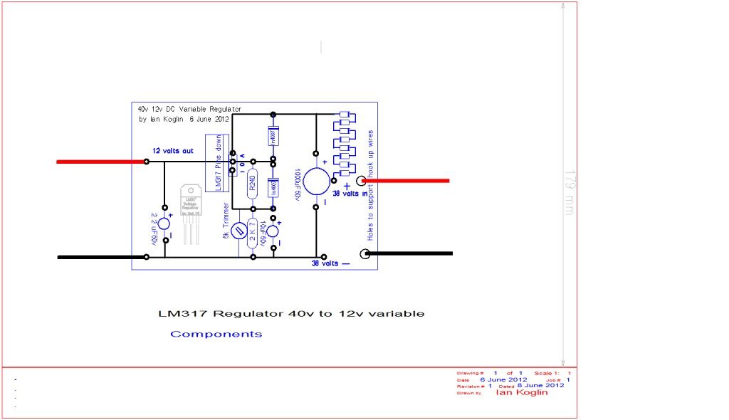


Here is the 555 Oscillator circuit
It as it oscillates and I turn the pot It shows a square wave that changes the Duty cycle But the volts output is only about 2 to 3 v
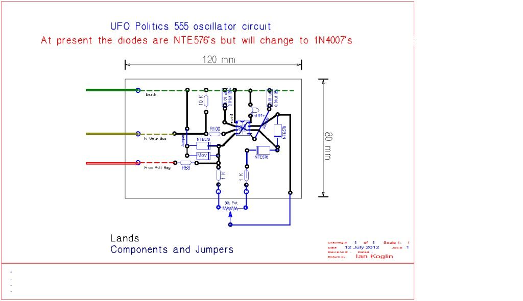


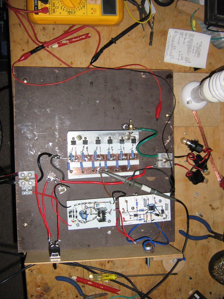
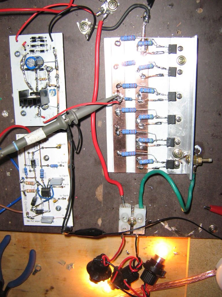
When I have the Regulator and the Oscillator connected to the circuit the bulb does not even flicker even if I move all the way thru the pot very slowly here is the circuit I have drawn here and a pic follows
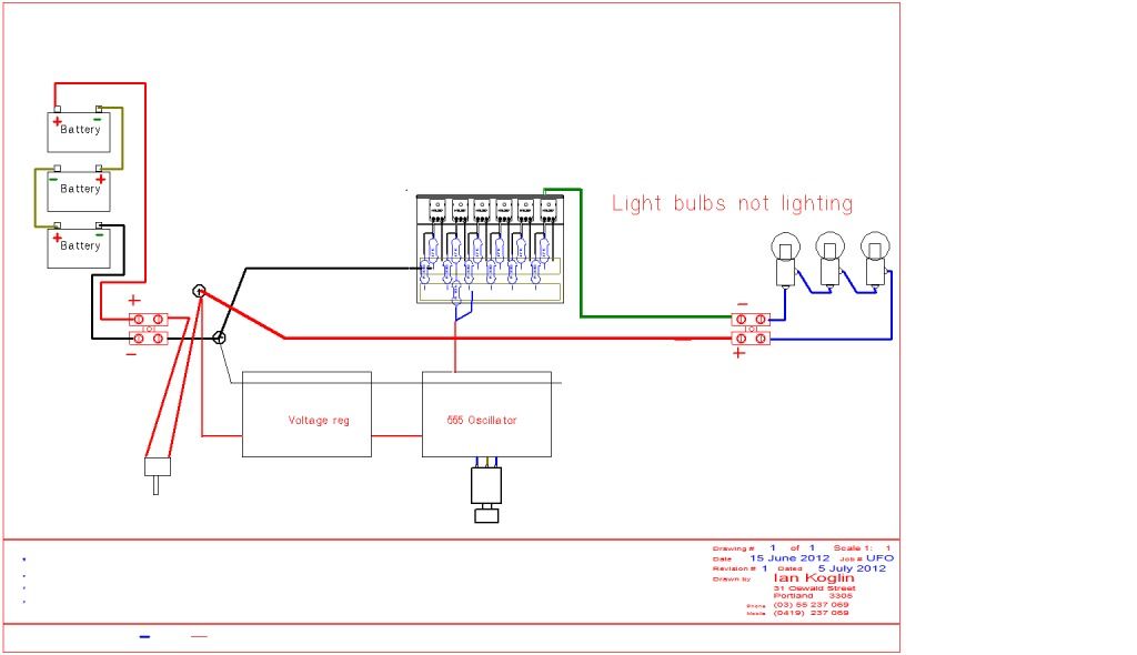


When I disconnect the Oscillator and connect the output of the regulator the lights do come on and very bright
the circuit is here and followed by a pic
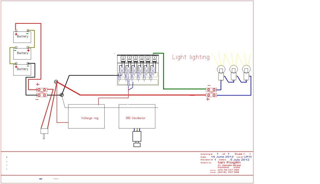


I captured a vid on my phone I do not know if it works as it Seems I cannot view my photos and vids my self but I was able to download the URL's


I really appreciate everything you are doing here especially being so busy and taking the time to help me

Kindest Regards
Digg this Post!Add Post to del.icio.usBookmark Post in TechnoratiFurl this Post!Live Bookmark this Post!Google Bookmark this Post!Yahoo Bookmark this Post! share on MyspaceShare on FacebookTweet this thread
Reply With Quote Multi-Quote This Message Quick reply to this message
  #1260 (permalink)   Report Post  
Old 07-13-2012, 01:59 PM
woopy woopy is online now
Senior Member
 
Join Date: Aug 2008
Posts: 288
Hi guys

For the interested here, i succesfully replicated the assymetric motor of Ufopolitics.

Discussion on the other thread

good luck at all

Laurent

Ufo assymetric motor part 1 - YouTube
Digg this Post!Add Post to del.icio.usBookmark Post in TechnoratiFurl this Post!Live Bookmark this Post!Google Bookmark this Post!Yahoo Bookmark this Post! share on MyspaceShare on FacebookTweet this thread
Reply With Quote Multi-Quote This Message Quick reply to this message
Reply


Quick Reply
Message:
Remove Text Formatting
Bold
Italic
Underline

Insert Image
Wrap [QUOTE] tags around selected text
 
Decrease Size
Increase Size
Options


Currently Active Users Viewing This Thread: 13 (2 members and 11 guests)
lamare, Bob Smith
Thread Tools Search this Thread
Search this Thread:

Advanced Search
Rate This Thread
Rate This Thread:

Posting Rules
You may post new threads
You may post replies
You may post attachments
You may edit your posts

vB code is On
Smilies are On
[IMG] code is On
HTML code is Off
Trackbacks are On
Pingbacks are On
Refbacks are On


All times are GMT. The time now is 11:04 PM.


Powered by vBulletin® Version 3.6.4
Copyright ©2000 - 2012, Jelsoft Enterprises Ltd.
Search Engine Optimization by vBSEO 3.0.0 RC8
2007 Copyright ? Energetic Forum? A Non Profit Corporation - All Rights Reserved