Energetic Forum  

Go Back   Energetic Forum > Energetic Forum Discussion > Renewable Energy
Welcome, lamare.
You last visited: Today at 08:48 AM
Private Messages: Unread 2, Total 30.
Homepage Energetic Science Ministries User CP FAQ Calendar Search New Posts Mark Forums Read Open Buddy List Log Out

Renewable Energy Discussion on various alternative energy, renewable energy, & free energy technologies. Also any discussion about the environment, global warming, and other related topics are welcome here.

Reply
 
LinkBack Thread Tools Search this Thread Rating: Thread Rating: 5 votes, 5.00 average.
  #271 (permalink)   Report Post  
Old Today, 03:24 AM
Beachcomber310 Beachcomber310 is offline
Junior Member
 
Join Date: Jul 2012
Posts: 1
Amazing work

I have been reading watching all the work done by people here at replicating this motor. My background is in Electronics and not in motor armature winding. All my motor build so far has been along the line of pulse motors and Newman Style motors so working with the type of motors that you are using for this project is not so easy for me. Even so I bought two Radio Shack motors to give it a try. Well it didn't go so well as I broke the commutator trying to get it off the motor. I am not giving up I am just going to try and find some bigger motors to work with. The Radio Shack motors are small. Tried getting the Traxxas Motor from Pep Boys. Went to 3 different Pep Boys stores and they were all out of the motor. So either they fail alot or everyone has been out buying the build these motors One thing that has me a little confused. In UFO's video he said the motor runs cold and there is little to no arcing of the commutator which is great. But in JohnG's I think was his name he said his motor did get fairly warm and in a few hours of running he burnt out a set of brushes. Is it possible that his may not have been wired quite right or the phasing off a bit? Just trying to get a better handle on this. It seems like a real breakthrough that has been suppressed for a very long time and I hope to be able make a good working unit of my own soon.

Thanks and keep up the great work people!!!!!

Beachcomber310
Digg this Post!Add Post to del.icio.usBookmark Post in TechnoratiFurl this Post!Live Bookmark this Post!Google Bookmark this Post!Yahoo Bookmark this Post! share on MyspaceShare on FacebookTweet this thread
Reply With Quote Multi-Quote This Message Quick reply to this message
  #272 (permalink)   Report Post  
Old Today, 03:55 AM
Turion's Avatar
Turion Turion is online now
Senior Member
 
Join Date: Nov 2009
Posts: 575
I am working on a generator now. Have to have something to do while I'm running tests! Bought out one radio shack and working on a second one!

Dave
__________________
Talent hits a target no one else can hit; Genius hits a target no one else can see. - Arthur Schopenhauer
Get it all on record now - get the films - get the witnesses -because somewhere down the road of history some bastard will get up and say that this never happened' General D.Eisenhower
The world we have created is a product of our thinking. It cannot be changed without changing our thinking. Albert Einstein
I aim to misbehave. - Malcolm Reynolds
Digg this Post!Add Post to del.icio.usBookmark Post in TechnoratiFurl this Post!Live Bookmark this Post!Google Bookmark this Post!Yahoo Bookmark this Post! share on MyspaceShare on FacebookTweet this thread
Reply With Quote Multi-Quote This Message Quick reply to this message
  #273 (permalink)   Report Post  
Old Today, 03:59 AM
Ufopolitics's Avatar
Ufopolitics Ufopolitics is online now
Senior Member
 
Join Date: Feb 2012
Location: US, Florida
Posts: 579
Hello Beachcomber310

Quote:
Originally Posted by Beachcomber310 View Post
I have been reading watching all the work done by people here at replicating this motor. My background is in Electronics and not in motor armature winding. All my motor build so far has been along the line of pulse motors and Newman Style motors so working with the type of motors that you are using for this project is not so easy for me. Even so I bought two Radio Shack motors to give it a try. Well it didn't go so well as I broke the commutator trying to get it off the motor. I am not giving up I am just going to try and find some bigger motors to work with. The Radio Shack motors are small. Tried getting the Traxxas Motor from Pep Boys. Went to 3 different Pep Boys stores and they were all out of the motor. So either they fail alot or everyone has been out buying the build these motors One thing that has me a little confused. In UFO's video he said the motor runs cold and there is little to no arcing of the commutator which is great. But in JohnG's I think was his name he said his motor did get fairly warm and in a few hours of running he burnt out a set of brushes. Is it possible that his may not have been wired quite right or the phasing off a bit? Just trying to get a better handle on this. It seems like a real breakthrough that has been suppressed for a very long time and I hope to be able make a good working unit of my own soon.

Thanks and keep up the great work people!!!!!

Beachcomber310
Hello and Welcome here,

That's great give it a try...is simple nothing out of the typical windings...just different hooks and connections type.

He burnt it because He was doing it with just one commutator in a smaller than the 5 pole body...He joined three cables at end and run through bearings contacts...it got hot, and was a bit cheaper model...but He got out some power to get a light going...so, still was a good testing...Motors were $1.00 each...lol

Welcome, as is good to know. We just don't need Motor builders, but also some Electronics Skills...

Regards


Ufopolitics
Digg this Post!Add Post to del.icio.usBookmark Post in TechnoratiFurl this Post!Live Bookmark this Post!Google Bookmark this Post!Yahoo Bookmark this Post! share on MyspaceShare on FacebookTweet this thread
Reply With Quote Multi-Quote This Message Quick reply to this message
  #274 (permalink)   Report Post  
Old Today, 04:01 AM
Ufopolitics's Avatar
Ufopolitics Ufopolitics is online now
Senior Member
 
Join Date: Feb 2012
Location: US, Florida
Posts: 579
That's great Dave!!

Quote:
Originally Posted by Turion View Post
I am working on a generator now. Have to have something to do while I'm running tests! Bought out one radio shack and working on a second one!

Dave

Awesome, and many thanks!!

Now Turion, I have noticed the one on the Picture (the Asymmetric one) has kind of not aligned properly upper-lower caps or holes for ventilation...are the brushes lined up?


Regards

Ufo

Last edited by Ufopolitics : Today at 04:05 AM.
Digg this Post!Add Post to del.icio.usBookmark Post in TechnoratiFurl this Post!Live Bookmark this Post!Google Bookmark this Post!Yahoo Bookmark this Post! share on MyspaceShare on FacebookTweet this thread
Reply With Quote Multi-Quote This Message Quick reply to this message
  #275 (permalink)   Report Post  
Old Today, 04:56 AM
john_g john_g is online now
Senior Member
 
Join Date: Jul 2008
Posts: 333
Quote:
Originally Posted by Beachcomber310 View Post
I have been reading watching all the work done by people here at replicating this motor. My background is in Electronics and not in motor armature winding. All my motor build so far has been along the line of pulse motors and Newman Style motors so working with the type of motors that you are using for this project is not so easy for me. Even so I bought two Radio Shack motors to give it a try. Well it didn't go so well as I broke the commutator trying to get it off the motor. I am not giving up I am just going to try and find some bigger motors to work with. The Radio Shack motors are small. Tried getting the Traxxas Motor from Pep Boys. Went to 3 different Pep Boys stores and they were all out of the motor. So either they fail alot or everyone has been out buying the build these motors One thing that has me a little confused. In UFO's video he said the motor runs cold and there is little to no arcing of the commutator which is great. But in JohnG's I think was his name he said his motor did get fairly warm and in a few hours of running he burnt out a set of brushes. Is it possible that his may not have been wired quite right or the phasing off a bit? Just trying to get a better handle on this. It seems like a real breakthrough that has been suppressed for a very long time and I hope to be able make a good working unit of my own soon.

Thanks and keep up the great work people!!!!!

Beachcomber310
Hi Beachcomber

Yes mine does get warm/hot during a long run but the brushes have not burnt on mine - there is no sparking at the commutator.

Regards

John
Digg this Post!Add Post to del.icio.usBookmark Post in TechnoratiFurl this Post!Live Bookmark this Post!Google Bookmark this Post!Yahoo Bookmark this Post! share on MyspaceShare on FacebookTweet this thread
Reply With Quote Multi-Quote This Message Quick reply to this message
  #276 (permalink)   Report Post  
Old Today, 05:25 AM
ewizard's Avatar
ewizard ewizard is offline
Senior Member
 
Join Date: Jan 2010
Location: Outside the Matrix
Posts: 643
Quote:
Originally Posted by Turion View Post
Test setup ready for a day of testing.
I look forward to your results as I believe you are going about this in a way that will give more good validation to the concepts UFO has shown us here. Are those couplings between motors just some plastic or vinyl type tubing? If so do you think they may slip at all?

I got sidetracked cleaning up the disaster zone in my shop so I still have 2 stock unmodded drill motors. Hopefully I can get somewhere with them tomorrow.
__________________
There is no important work, there are only a series of moments to demonstrate your mastery and impeccability. Quote from Almine
Digg this Post!Add Post to del.icio.usBookmark Post in TechnoratiFurl this Post!Live Bookmark this Post!Google Bookmark this Post!Yahoo Bookmark this Post! share on MyspaceShare on FacebookTweet this thread
Reply With Quote Multi-Quote This Message Quick reply to this message
  #277 (permalink)   Report Post  
Old Today, 09:57 AM
woopy woopy is online now
Senior Member
 
Join Date: Aug 2008
Posts: 288
Hi Netica

thank's very much por the connection plan, very helpfull.

So now my "school motor" generate 12. 5 volt for a measured 8.12 input volts.

Yep a lot to learn.


Hi Dad Hav

No no i am not a long experimenter on this motor, as i began my replication on the 12 of july that is to say 4 days ago HiHi!
And i am trying hard to rightly understand what is going on.
So i am in full discouvering mode with enthousiasm.

So i am now testing all sort of connections and tuning and i am far to be ready for so called scientific measurement .
By chance and for once there is a lot of very good replicators arround, and i have no doubt that this project will go forward and fast.

good luck at all

Laurent
Digg this Post!Add Post to del.icio.usBookmark Post in TechnoratiFurl this Post!Live Bookmark this Post!Google Bookmark this Post!Yahoo Bookmark this Post! share on MyspaceShare on FacebookTweet this thread
Reply With Quote Multi-Quote This Message Quick reply to this message
  #278 (permalink)   Report Post  
Old Today, 10:06 AM
DadHav DadHav is online now
Junior Member
 
Join Date: Dec 2008
Posts: 18
Quote:
Originally Posted by Ufopolitics View Post
Hello Dad Hav,


I am very sorry I have not being able to respond before to you, since I have been dedicated entirely to finish my work here. I hope you could forgive me.

I think I could help Woopy just a bit, about explaining your concerns and questions about this Systems...

This Machines as Motor function related have many advantages over any of the Symmetrical kind.

1- Effective Voltage (Ev) at Armature/Rotor is greater than Input Voltage (Ea), since the power that used to be called C EMF in the past Symmetrical System...and was of "negative value", therefore, had to be deducted from Ea...Now has become of Positive value, therefore, on complete assistance to Rotation Force and is added to Ev.

1-a: This positive parameter on our side, generates an increase of force volume on this motors, beyond the short circuit ones and of course...of the latest BLDC Motor...that is a complete crash of flow in its Star or Delta windings...

1-b: This positive factor allows Us, to "no longer sacrifice" one of the desired parameters as are RPM's or Torque like We all have been taught it MUST be done...sorry..but not anymore, yes, We can have both Worlds together.

2-The Source or Battery consumption reduces to Milli-volts levels, when compared to a short circuit reversed polarity symmetrical motor...

3- This Motors do not have reversed or negative feedback "parasitical" and randomly traveling currents hitting and frying our electronic sensitive components anymore...The Flow has been oriented to go "One Way Only"...

4-This Motors do not require "massive amperage" to operate and develop their work at very efficient levels...The Typical Amperage requirements of Symmetrical Machines, was entirely due, to their constant wrestling electrical-current forces within their rotating components...Reminding all here, that Amperage is a "Population Value" of Electrons at a given section of the conductor, therefore, is understood, that if we have a machine that has a very populated Incoming Traffic towards Our Traffic Flow...the measurements at any given part of such conductors...Our meters will read "Mega Congested Amperage Area" in just that section.

Therefore We are all gonna have to familiarize with the so called "Nonsensical" arguments of many, many Inventors, the list is huge, who stated, their "Machines worked only on Voltage"...or "They did not require a Higher Amperage"...and so on, they kept repeating to exhaustion, and were all taken as "ignorant and not properly skilled in the Art, or in the fields"...

5- This Motors allow many other circuit-windings designs within the same armature, comprehending wider poles configurations, that increases their "throw out angles of magnetic forces " developing speeds beyond our knowledge in any electrical motor known so far.
As they also allow an "Start-Up Winding" of shorter poles for greater torque in much heavier machines...it will become a kind of Electromagnetic Transmission within just one embodiment.

6-This Machines only "Turn On and Turn Off" their Coils, in order to achieve rotation, therefore is understood, that Electronic Signaling Circuitry based on just Opto Isolators could be employed, reducing all friction drag and heat... But mainly leaving to Electronics Highly developed logic circuitry to control their operations in a more accurate and faster response fashion.

7- We can combine, add, modulate and exchange this machines internal and external components as We desire, and that includes the fusion of Motors and Generators in just One Assembly...in order to obtain our specific design requests.

There are many more advantages to them...and then some we never thought off will come in near future...and I know We will.

This Machines will bring a new age for Motor and Generator applications...World wide...the list of benefits is endless and limited only to our capacity and imagination...


Regards


Ufopolitics
First thank you for addressing my questions. You may know that I've been designing and building motors for a long time so your claims have me interested but cautious. Cautious because I've wasted thousands of hours following other people and their claims of over unity. All of what you say may be true but their hasn't been anyone to provide tests which back up your claims. Or maybe I've missed them somewhere. Every thing I see so far is drawing a lot of current. So far measuring an increase in voltage does not mean anything more than a standard generator effect unless you can draw a load and not have the current draw go up on the input at the same time. A modified motor must be more efficient than the original. If I swing an 8-6 prop on the original RS motor at a certain RPM at a certain wattage based on the voltage and current, then you should be able to swing the prop at the same RPM with much less wattage with the modified motor. As complicated and technical as your explanation is to me, no one has provided a simple test like I propose to show us there really is an advantage to this motor. An easy to understand straight forward example of how good this modification is. I'm hoping to see something that will send me down to my workshop and get me busy but until then I'm going to take my time and put one of these together at my leisure.
Thank you very much UFO for answering me. I really hope to see a real world application from this group. If there is a video example you care to reference I'd be glad to look at it and give my opinion. I've looked at your videos but you do not test in a manner that proves what you say. But of course that's only my opinion and I really don't insist that you cater to me. The truth good or bad will come out sooner or later. I hope for the best.
John H
Digg this Post!Add Post to del.icio.usBookmark Post in TechnoratiFurl this Post!Live Bookmark this Post!Google Bookmark this Post!Yahoo Bookmark this Post! share on MyspaceShare on FacebookTweet this thread
Reply With Quote Multi-Quote This Message Quick reply to this message
  #279 (permalink)   Report Post  
Old Today, 10:31 AM
waterfall waterfall is offline
Junior Member
 
Join Date: Jul 2012
Posts: 4
Quote:
Originally Posted by DadHav View Post
First thank you for addressing my questions. You may know that I've been designing and building motors for a long time so your claims have me interested but cautious. Cautious because I've wasted thousands of hours following other people and their claims of over unity. All of what you say may be true but their hasn't been anyone to provide tests which back up your claims. Or maybe I've missed them somewhere. Every thing I see so far is drawing a lot of current. So far measuring an increase in voltage does not mean anything more than a standard generator effect unless you can draw a load and not have the current draw go up on the input at the same time. A modified motor must be more efficient than the original. If I swing an 8-6 prop on the original RS motor at a certain RPM at a certain wattage based on the voltage and current, then you should be able to swing the prop at the same RPM with much less wattage with the modified motor. As complicated and technical as your explanation is to me, no one has provided a simple test like I propose to show us there really is an advantage to this motor. An easy to understand straight forward example of how good this modification is. I'm hoping to see something that will send me down to my workshop and get me busy but until then I'm going to take my time and put one of these together at my leisure.
Thank you very much UFO for answering me. I really hope to see a real world application from this group. If there is a video example you care to reference I'd be glad to look at it and give my opinion. I've looked at your videos but you do not test in a manner that proves what you say. But of course that's only my opinion and I really don't insist that you cater to me. The truth good or bad will come out sooner or later. I hope for the best.
John H
As long as we use combination of:copper and pm. magnets-there will be some magnetic drag..I would like to see somebody test it with copper in stator-not pm. magnets..Than i think we will have zero magnetic drag,of course with proper timing!!
waterfall
Digg this Post!Add Post to del.icio.usBookmark Post in TechnoratiFurl this Post!Live Bookmark this Post!Google Bookmark this Post!Yahoo Bookmark this Post! share on MyspaceShare on FacebookTweet this thread
Reply With Quote Multi-Quote This Message Quick reply to this message
  #280 (permalink)   Report Post  
Old Today, 10:58 AM
kEhYo77's Avatar
kEhYo77 kEhYo77 is offline
Member
 
Join Date: Jul 2008
Posts: 53
Hi Ufo & All
Finally my motors arrived so I'm getting to work... Hollyday fun witches hunt!


They're quite nice 5 poles having slip bearings on both ends of the shaft and they run quiet.


and a nonconductive housing (no eddies)


kEhYo

Last edited by kEhYo77 : Today at 03:48 PM.
Digg this Post!Add Post to del.icio.usBookmark Post in TechnoratiFurl this Post!Live Bookmark this Post!Google Bookmark this Post!Yahoo Bookmark this Post! share on MyspaceShare on FacebookTweet this thread
Reply With Quote Multi-Quote This Message Quick reply to this message
  #281 (permalink)   Report Post  
Old Today, 12:53 PM
Ganzha's Avatar
Ganzha Ganzha is offline
Member
 
Join Date: Nov 2011
Location: near of Munich
Posts: 68
Send a message via Skype™ to Ganzha
hi
how you going to open them
i did today but it is hard job
i have the same type
johnson but from chine//// i think
Digg this Post!Add Post to del.icio.usBookmark Post in TechnoratiFurl this Post!Live Bookmark this Post!Google Bookmark this Post!Yahoo Bookmark this Post! share on MyspaceShare on FacebookTweet this thread
Reply With Quote Multi-Quote This Message Quick reply to this message
  #282 (permalink)   Report Post  
Old Today, 12:56 PM
Ufopolitics's Avatar
Ufopolitics Ufopolitics is online now
Senior Member
 
Join Date: Feb 2012
Location: US, Florida
Posts: 579
Hello and Good morning to All

Quote:
Originally Posted by waterfall View Post
As long as we use combination of:copper and pm. magnets-there will be some magnetic drag..I would like to see somebody test it with copper in stator-not pm. magnets..Than i think we will have zero magnetic drag,of course with proper timing!!
waterfall
Hello to All, Hello Waterfall,Hello Dad Hav, Hello kEhYo77 (Grreat Babies there!!)


Good morning to All,

Yes, I have used Copper_to_Copper set up, and You are absolutely right, They perform much better there, and besides the fact you have mentioned (lack of existence of constant magnetic drag from PM's) there is more to it...

We could pulse this Stators-Armatures at same exact controlled oscillations, then We will get a much better synchronized and managed displacement all along the performance.

This Asymmetrical Armatures will work with Symmetrical Dual, Quad and whatever "Pairs" of numbers combinations you decide to choose for your design...of the Stators Fields. My best connections between them, at this side of the "Road" is to connect them in Parallel, in order that Armature-Stator receive the same exact pulsed signal without distortion-noise from resistance or capacitance on either coils...The other "side" of this is even greater, as the way Radiant Energy induces through air faster than normal Hot Flux...If We maintain the SAME DIRECTION of Windings at Stator and Armatures....Then We get HER to also Induce HER Strength in those Inner Armature Coils...just as I have explained in my first post here...(I am closing the loop, grrreat!!)...Just like a very powerful transformer, but transmitting the energy even though "Isolated Secondaries" are rotating at very high speeds...SHE will "catch up", just because HER great ultra fast speed, way faster than normal electricity...

The Third Advantage to this...(yes, and there is still more), is the fact, that as I have mentioned in my previous Thread about Tapping Radiant Energy with my Motors...We can add Bifilar Wound Stators and get Energy from them through Negative Induction* just using a Pair of Diodes, like I have described and explained there, in my previous little coil set up lighting Neons and CFL's...

A Bifilar Wound Stator will create a much stronger Magnetic Field than just a single wire...keeping resistance at low values, but never below one Ohm...or you would be risking your controller electronics, MOSFET's as low voltage signaling circuitry by too high stresses from HER, coming back at Us at speeds our tronic's can't handle (it never did, as a matter of fact, we've been "patching" so far to get by "half way decently")...but we, at that thread are trying to design enough powerful "Tronics" to handle HER speeds through Isolated Opto's.


There is also the Asymmetrical Wound Stators for this arrangements...but I rather display that part further on as we get the replicas functioning and performing the way I have said...then You all will "finally" trust and believe in me...

Many Regards and thanks


Ufopolitics


[IMG][/IMG]
Digg this Post!Add Post to del.icio.usBookmark Post in TechnoratiFurl this Post!Live Bookmark this Post!Google Bookmark this Post!Yahoo Bookmark this Post! share on MyspaceShare on FacebookTweet this thread
Reply With Quote Multi-Quote This Message Quick reply to this message
  #283 (permalink)   Report Post  
Old Today, 12:59 PM
Turion's Avatar
Turion Turion is online now
Senior Member
 
Join Date: Nov 2009
Posts: 575
UFO,
The brushes are aligned in the conversion. I rotated the commutator slowly and checked for alignment between segments. And it runs great. If I look through the openings in the motor case, I can see that the screws inside that hold the brushes down are aligned with each other, but the casing isn't for some reason. Maybe there is more than one way the end cap can snap into place on the casing if you rotate it.

The generator is wired exactly the same as the motor, correct? If that is so, I will have a third setup to add to my collection by the end of the day....a modified motor running a modified generator. I mean it's only four more motors and those folks at Radio Shack LOVE to see me come in the door.

Someone asked how the shafts are connected. I took a Bic pen apart and the cartridge inside that holds the ink...I cut off some sections. I put epoxy on the ends of the shaft and slid this on. It is an extremely tight fit, which is what I wanted.

Got some errands to run this morning, then will spend the afternoon testing and building another motor and generator. I may have to buy another Bic pen!

Dave
__________________
Talent hits a target no one else can hit; Genius hits a target no one else can see. - Arthur Schopenhauer
Get it all on record now - get the films - get the witnesses -because somewhere down the road of history some bastard will get up and say that this never happened' General D.Eisenhower
The world we have created is a product of our thinking. It cannot be changed without changing our thinking. Albert Einstein
I aim to misbehave. - Malcolm Reynolds
Digg this Post!Add Post to del.icio.usBookmark Post in TechnoratiFurl this Post!Live Bookmark this Post!Google Bookmark this Post!Yahoo Bookmark this Post! share on MyspaceShare on FacebookTweet this thread
Reply With Quote Multi-Quote This Message Quick reply to this message
  #284 (permalink)   Report Post  
Old Today, 01:00 PM
Ufopolitics's Avatar
Ufopolitics Ufopolitics is online now
Senior Member
 
Join Date: Feb 2012
Location: US, Florida
Posts: 579
Opening Them...

Quote:
Originally Posted by Ganzha View Post
hi
how you going to open them
i did today but it is hard job
i have the same type
johnson but from chine//// i think

Hello Ganzha,


Those Motors are just great, very well built, similar to TRAXXAS Body.

The easiest way to open them is with small (but very strong and good quality, or will brake, I broke a nice pair... ) cutting pliers...grabbing the very small bent tabs by factory impact, but NOT TO CUT THEM, just to clear them out from cap...metal pieces may come apart...but that's the way I did it...


Regards


Ufopolitics
Digg this Post!Add Post to del.icio.usBookmark Post in TechnoratiFurl this Post!Live Bookmark this Post!Google Bookmark this Post!Yahoo Bookmark this Post! share on MyspaceShare on FacebookTweet this thread
Reply With Quote Multi-Quote This Message Quick reply to this message
  #285 (permalink)   Report Post  
Old Today, 01:20 PM
Ufopolitics's Avatar
Ufopolitics Ufopolitics is online now
Senior Member
 
Join Date: Feb 2012
Location: US, Florida
Posts: 579
Hello and Good morning Turion

Quote:
Originally Posted by Turion View Post
UFO,
The brushes are aligned in the conversion. I rotated the commutator slowly and checked for alignment between segments. And it runs great. If I look through the openings in the motor case, I can see that the screws inside that hold the brushes down are aligned with each other, but the casing isn't for some reason. Maybe there is more than one way the end cap can snap into place on the casing if you rotate it.

The generator is wired exactly the same as the motor, correct? If that is so, I will have a third setup to add to my collection by the end of the day....a modified motor running a modified generator. I mean it's only four more motors and those folks at Radio Shack LOVE to see me come in the door.

Someone asked how the shafts are connected. I took a Bic pen apart and the cartridge inside that holds the ink...I cut off some sections. I put epoxy on the ends of the shaft and slid this on. It is an extremely tight fit, which is what I wanted.

Got some errands to run this morning, then will spend the afternoon testing and building another motor and generator. I may have to buy another Bic pen!

Dave


Hello Dave,


Yes, This Motors and Generators are the same (at least for this testing)...don't want to "complicate" things now expanding to Gen's...This Motors will also generate as well.

Now, I wrote before a Method to check that your connections between armature coils-brushes alignment are perfectly right, with a continuity meter at terminals (Input-Output also, better if two meters at each side to make test simultaneously on both, they should mark exactly at same points) by rotating shaft slowly..."feeling" the in between comm-brush fall-rise contacts one by one, mark starting point till rotation closes the 360.

Normally, to take even better advantage of the great torque of just a single Motor...The Generator could be winded with more Copper Windings, but we are limited because of this small Radio Shack Motor...However it could turn bigger motors like the Traxxas body(same as kEhYo77 but Three Poles) easy...then we will get even more "Overunity".

Turion check the way to connect face to face...that I posted previously here, please...You could get the extra "juices" from Motor also...and connect them in series to Gen Output...but Gen is reversed electrically connected as Motor was conceived...since is counter rotating Motor...other wise will oppose when magnetic fields are induced by rotation at Generator side.

Please make a video if you could...


Many thanks!!


Regards


Ufopolitcs
Digg this Post!Add Post to del.icio.usBookmark Post in TechnoratiFurl this Post!Live Bookmark this Post!Google Bookmark this Post!Yahoo Bookmark this Post! share on MyspaceShare on FacebookTweet this thread
Reply With Quote Multi-Quote This Message Quick reply to this message
  #286 (permalink)   Report Post  
Old Today, 01:39 PM
waterfall waterfall is offline
Junior Member
 
Join Date: Jul 2012
Posts: 4
Quote:
Originally Posted by Ufopolitics View Post
Hello to All, Hello Waterfall,Hello Dad Hav, Hello kEhYo77 (Grreat Babies there!!)


Good morning to All,

Yes, I have used Copper_to_Copper set up, and You are absolutely right, They perform much better there, and besides the fact you have mentioned (lack of existence of constant magnetic drag from PM's) there is more to it...

We could pulse this Stators-Armatures at same exact controlled oscillations, then We will get a much better synchronized and managed displacement all along the performance.

This Asymmetrical Armatures will work with Symmetrical Dual, Quad and whatever "Pairs" of numbers combinations you decide to choose for your design...of the Stators Fields. My best connections between them, at this side of the "Road" is to connect them in Parallel, in order that Armature-Stator receive the same exact pulsed signal without distortion-noise from resistance or capacitance on either coils...The other "side" of this is even greater, as the way Radiant Energy induces through air faster than normal Hot Flux...If We maintain the SAME DIRECTION of Windings at Stator and Armatures....Then We get HER to also Induce HER Strength in those Inner Armature Coils...just as I have explained in my first post here...(I am closing the loop, grrreat!!)...Just like a very powerful transformer, but transmitting the energy even though "Isolated Secondaries" are rotating at very high speeds...SHE will "catch up", just because HER great ultra fast speed, way faster than normal electricity...

The Third Advantage to this...(yes, and there is still more), is the fact, that as I have mentioned in my previous Thread about Tapping Radiant Energy with my Motors...We can add Bifilar Wound Stators and get Energy from them through Negative Induction* just using a Pair of Diodes, like I have described and explained there, in my previous little coil set up lighting Neons and CFL's...

A Bifilar Wound Stator will create a much stronger Magnetic Field than just a single wire...keeping resistance at low values, but never below one Ohm...or you would be risking your controller electronics, MOSFET's as low voltage signaling circuitry by too high stresses from HER, coming back at Us at speeds our tronic's can't handle (it never did, as a matter of fact, we've been "patching" so far to get by "half way decently")...but we, at that thread are trying to design enough powerful "Tronics" to handle HER speeds through Isolated Opto's.


There is also the Asymmetrical Wound Stators for this arrangements...but I rather display that part further on as we get the replicas functioning and performing the way I have said...then You all will "finally" trust and believe in me...

Many Regards and thanks


Ufopolitics


[IMG][/IMG]
Hi ufopolitics..you don't stop to surprise us..
"We could pulse this Stators-Armatures at same exact controlled oscillations, then We will get a much better synchronized and managed displacement all along the performance."

Does it mean that we can electronically pulsed both-rotor and stator coils IN THE PRECISE SAME TIME IF THE ROTOR COILS ARE IN ASYMMETRIC STATE???
Also that stator coils could be in any symmetric mode?
You just need to pulse them(rotor-stator) in parallel fashion??
Thanks friend
waterfall
Digg this Post!Add Post to del.icio.usBookmark Post in TechnoratiFurl this Post!Live Bookmark this Post!Google Bookmark this Post!Yahoo Bookmark this Post! share on MyspaceShare on FacebookTweet this thread
Reply With Quote Multi-Quote This Message Quick reply to this message
  #287 (permalink)   Report Post  
Old Today, 01:39 PM
bbem bbem is offline
Member
 
Join Date: Sep 2011
Posts: 77
Removing lacquer/email from magnet wire

Ufo,
Maybe it was asked before, but then I missed it.
What is the best way to remove the lacquer/email from the magnet wire?

Regards,
Bert

ps. Was thinking about nail polish remover
Digg this Post!Add Post to del.icio.usBookmark Post in TechnoratiFurl this Post!Live Bookmark this Post!Google Bookmark this Post!Yahoo Bookmark this Post! share on MyspaceShare on FacebookTweet this thread
Reply With Quote Multi-Quote This Message Quick reply to this message
  #288 (permalink)   Report Post  
Old Today, 01:50 PM
Ufopolitics's Avatar
Ufopolitics Ufopolitics is online now
Senior Member
 
Join Date: Feb 2012
Location: US, Florida
Posts: 579
Razor blades...Bert

Quote:
Originally Posted by bbem View Post
Ufo,
Maybe it was asked before, but then I missed it.
What is the best way to remove the lacquer/email from the magnet wire?

Regards,
Bert

ps. Was thinking about nail polish remover

Good morning Bert,

I just use a razor blade Bert, since it is a small area to be connected to commutator hooks...or are you doing "something else"?...lol

If you want to remove larger areas then Enamel reducer or lacquer thinner will do...as also Acetone, but if a "drop" falls on whole Roll you lost it...so be careful.


Regards


Ufopolitics
Digg this Post!Add Post to del.icio.usBookmark Post in TechnoratiFurl this Post!Live Bookmark this Post!Google Bookmark this Post!Yahoo Bookmark this Post! share on MyspaceShare on FacebookTweet this thread
Reply With Quote Multi-Quote This Message Quick reply to this message
  #289 (permalink)   Report Post  
Old Today, 01:53 PM
wonza wonza is online now
Member
 
Join Date: Jun 2012
Posts: 40
I just used sandpaper. I read woopi used a flame though
Digg this Post!Add Post to del.icio.usBookmark Post in TechnoratiFurl this Post!Live Bookmark this Post!Google Bookmark this Post!Yahoo Bookmark this Post! share on MyspaceShare on FacebookTweet this thread
Reply With Quote Multi-Quote This Message Quick reply to this message
  #290 (permalink)   Report Post  
Old Today, 02:13 PM
b_rads b_rads is offline
Senior Member
 
Join Date: Feb 2011
Location: Alabama, South East U.S.
Posts: 181
Quote:
Originally Posted by Ufopolitics View Post
Hello and Welcome here,
.....................
He burnt it because He was doing it with just one commutator in a smaller than the 5 pole body...He joined three cables at end and run through bearings contacts...it got hot, and was a bit cheaper model...but He got out some power to get a light going...so, still was a good testing...Motors were $1.00 each...lol
......................
Ufopolitics
Maybe I can clear up what my test was about.

The little battery fan motor from the dollar store is about as cheaply made as you can get. The brushes are very thin gage copper foil, certainly not made for 1.5 amps. I used the higher power as it showed exaggerated differences between the motors. Comparing unmodified to modified motors is comparing apples to oranges, but does give expected baseline results to compare with.

Retested with new unmodified motor and modified motor with new brush cap. The unmodified results: 2.6 Volts unloaded (2 AA batteries) ran the motor at 2 volts and 220mA for 0.44 watts. The modified ran at 1.5 volts and 280mA for 0.42 watts. Putting ground to the case does act like a resistor dropping the voltage. For this I got higher RPM’s (approx 700) plus generator output – enough to light an LED.

Using the 2 AA batteries, I do not see any abnormal wearing of the brushes nor could I tell that the motor was running hotter. I will be attempting the slip-ring method on a better motor next to confirm the results I saw in this test. All in All, this test did confirm that the motor did run more efficiently, at higher RPM’s, and with generator output as a bonus.

Brad S

Last edited by b_rads : Today at 02:18 PM.
Digg this Post!Add Post to del.icio.usBookmark Post in TechnoratiFurl this Post!Live Bookmark this Post!Google Bookmark this Post!Yahoo Bookmark this Post! share on MyspaceShare on FacebookTweet this thread
Reply With Quote Multi-Quote This Message Quick reply to this message
  #291 (permalink)   Report Post  
Old Today, 02:20 PM
Ufopolitics's Avatar
Ufopolitics Ufopolitics is online now
Senior Member
 
Join Date: Feb 2012
Location: US, Florida
Posts: 579
Yes they do work better by pulsing Stators...

Quote:
Originally Posted by waterfall View Post
Hi ufopolitics..you don't stop to surprise us..
"We could pulse this Stators-Armatures at same exact controlled oscillations, then We will get a much better synchronized and managed displacement all along the performance."

Does it mean that we can electronically pulsed both-rotor and stator coils IN THE PRECISE SAME TIME IF THE ROTOR COILS ARE IN ASYMMETRIC STATE???
Also that stator coils could be in any symmetric mode?
You just need to pulse them(rotor-stator) in parallel fashion??
Thanks friend
waterfall

Hello Waterfall,

Thanks,

Yes indeed, Waterfall, remember the "signal" to armatures via brushes, gets to "ONLY ONE" (or may be two- at most- if Brush is touching the "In-between" area of contacts therefore connected in parallel) Pairs of Coils isolated from the rest...So take this "Momentum" of rotation into a "Still Paused Frame" and analyze that set up- connections.. We have a Transformer Pulsing Primary(Stator) ..into One or Two Secondaries (Armature Coils)...per nano second of rotation...but that are also set in a Attraction-Repulsion "Fashion Mode" related to Magnetic Fields dispositions...so, we get a sudden drastic mechanical force that replaces Secondary Coils by the "next in line" waiting...to restart the process again...While, already charged, now disconnected Secondary, travels to EXIT OUTPUT Brushes to "deliver" its charge and done with his assignment ...to get "back in line"...This process is excellent, since we are granting them to rest for a bit, thanks to separation from contacts...on every coil in the configuration...time to cool off...discharge go back and recharge...
Therefore pulsing the Stator gives the advantages to REALLY CONTROL the rotation of Inner Coils...from movements as slow as only a Servo-Motor could do...with all the Gear boxes attached to it...all the way to ultra-fast speeds regulated by Stator pulsed signals that create a pulsing Magnetic Field...now, pulsing the Stator magnetic field, creates an inductive collapse...and then Radiant gets in our system...but I will complicate my explanation if I keep going here...however, this is the BEST PART...


Regards


Ufopolitcs
Digg this Post!Add Post to del.icio.usBookmark Post in TechnoratiFurl this Post!Live Bookmark this Post!Google Bookmark this Post!Yahoo Bookmark this Post! share on MyspaceShare on FacebookTweet this thread
Reply With Quote Multi-Quote This Message Quick reply to this message
  #292 (permalink)   Report Post  
Old Today, 02:23 PM
DadHav DadHav is online now
Junior Member
 
Join Date: Dec 2008
Posts: 18
Quote:
Originally Posted by woopy View Post
Hi Netica

thank's very much por the connection plan, very helpfull.

So now my "school motor" generate 12. 5 volt for a measured 8.12 input volts.

Yep a lot to learn.


Hi Dad Hav

No no i am not a long experimenter on this motor, as i began my replication on the 12 of july that is to say 4 days ago HiHi!
And i am trying hard to rightly understand what is going on.
So i am in full discouvering mode with enthousiasm.

So i am now testing all sort of connections and tuning and i am far to be ready for so called scientific measurement .
By chance and for once there is a lot of very good replicators arround, and i have no doubt that this project will go forward and fast.

good luck at all

Laurent
Hello Laurent. I'm always in discovery mode, but my time is running out so I get a little impatient at times and people take me the wrong way. I'm here because I would like to see this be a brilliant discovery and I would like to get into a more sophisticated mode, hopefully where my expertise lies. If this can be done and be an improvement to brushless motors then I'm all eyes and ears and hands on I might add. I'm subscribed to you video channel and always look forward to to seeing something from you when I get my updates from YouTube. If you haven't been over to my channel have a look at one of my motor building tutorials:
Brushless Motor Construction - YouTube
Good luck with your project.
John H.
Digg this Post!Add Post to del.icio.usBookmark Post in TechnoratiFurl this Post!Live Bookmark this Post!Google Bookmark this Post!Yahoo Bookmark this Post! share on MyspaceShare on FacebookTweet this thread
Reply With Quote Multi-Quote This Message Quick reply to this message
  #293 (permalink)   Report Post  
Old Today, 03:03 PM
DadHav DadHav is online now
Junior Member
 
Join Date: Dec 2008
Posts: 18
Double Shaft

Quote:
Originally Posted by Ufopolitics View Post
Hello Bert,

Hey, I was just kidding...about the lazy guy...did not meant for you to take it apart...lol

Listen, how many Amps-Volts are you getting out of just the Output terminals, not bridged?

30 is kind of a fine wire, what kind of body you have there?...last time I saw the 7 poles body..similar or could you get a bit higher awg, less turns...I did my three poles TRAXXAS with 26...

Let me know


Regards


Ufopolitics
UFO. I can't remember who suggested putting the shaft in from each side, but it can be done. There has to be some careful polishing after though to get the shaft to run smooth in the bushings. I was wondering since an overlap wind produces a high speed motor already would it be worth a try to increase the number of winds on the prototype? The original motor had 70 turns. Would more than 25 turns fit. Here's a video of the double shaft but I think a single shaft would be the best option:
Double Shaft.mp4 - YouTube
John H
Digg this Post!Add Post to del.icio.usBookmark Post in TechnoratiFurl this Post!Live Bookmark this Post!Google Bookmark this Post!Yahoo Bookmark this Post! share on MyspaceShare on FacebookTweet this thread
Reply With Quote Multi-Quote This Message Quick reply to this message
  #294 (permalink)   Report Post  
Old Today, 03:09 PM
DadHav DadHav is online now
Junior Member
 
Join Date: Dec 2008
Posts: 18
Quote:
Originally Posted by waterfall View Post
Hi ufopolitics..you don't stop to surprise us..
"We could pulse this Stators-Armatures at same exact controlled oscillations, then We will get a much better synchronized and managed displacement all along the performance."

Does it mean that we can electronically pulsed both-rotor and stator coils IN THE PRECISE SAME TIME IF THE ROTOR COILS ARE IN ASYMMETRIC STATE???
Also that stator coils could be in any symmetric mode?
You just need to pulse them(rotor-stator) in parallel fashion??
Thanks friend
waterfall
Quick question. Is that a model airplane motor starter? I have a few of them but thought I'd get comfortable before taking them apart.
John H.
Digg this Post!Add Post to del.icio.usBookmark Post in TechnoratiFurl this Post!Live Bookmark this Post!Google Bookmark this Post!Yahoo Bookmark this Post! share on MyspaceShare on FacebookTweet this thread
Reply With Quote Multi-Quote This Message Quick reply to this message
  #295 (permalink)   Report Post  
Old Today, 03:19 PM
waterfall waterfall is offline
Junior Member
 
Join Date: Jul 2012
Posts: 4
Yes they do work better by pulsing Stators

Quote:
Originally Posted by Ufopolitics View Post
Hello Waterfall,

Thanks,

Yes indeed, Waterfall, remember the "signal" to armatures via brushes, gets to "ONLY ONE" (or may be two- at most- if Brush is touching the "In-between" area of contacts therefore connected in parallel) Pairs of Coils isolated from the rest...So take this "Momentum" of rotation into a "Still Paused Frame" and analyze that set up- connections.. We have a Transformer Pulsing Primary(Stator) ..into One or Two Secondaries (Armature Coils)...per nano second of rotation...but that are also set in a Attraction-Repulsion "Fashion Mode" related to Magnetic Fields dispositions...so, we get a sudden drastic mechanical force that replaces Secondary Coils by the "next in line" waiting...to restart the process again...While, already charged, now disconnected Secondary, travels to EXIT OUTPUT Brushes to "deliver" its charge and done with his assignment ...to get "back in line"...This process is excellent, since we are granting them to rest for a bit, thanks to separation from contacts...on every coil in the configuration...time to cool off...discharge go back and recharge...
Therefore pulsing the Stator gives the advantages to REALLY CONTROL the rotation of Inner Coils...from movements as slow as only a Servo-Motor could do...with all the Gear boxes attached to it...all the way to ultra-fast speeds regulated by Stator pulsed signals that create a pulsing Magnetic Field...now, pulsing the Stator magnetic field, creates an inductive collapse...and then Radiant gets in our system...but I will complicate my explanation if I keep going here...however, this is the BEST PART...


Regards


Ufopolitcs
Hi Ufopolitcs

I know you work like a "horse" and i don't want you to spent your valued time like an "answering machine",just would like if you can upload video of your working model with copper-copper fashion mode like on your picture with timing switching precise info and performance data!
Thanks for all your efforts!
waterfall
Digg this Post!Add Post to del.icio.usBookmark Post in TechnoratiFurl this Post!Live Bookmark this Post!Google Bookmark this Post!Yahoo Bookmark this Post! share on MyspaceShare on FacebookTweet this thread
Reply With Quote Multi-Quote This Message Quick reply to this message
  #296 (permalink)   Report Post  
Old Today, 03:25 PM
Ufopolitics's Avatar
Ufopolitics Ufopolitics is online now
Senior Member
 
Join Date: Feb 2012
Location: US, Florida
Posts: 579
Hello Dad Hav

Quote:
Originally Posted by DadHav View Post
Quick question. Is that a model airplane motor starter? I have a few of them but thought I'd get comfortable before taking them apart.
John H.
Hello Dad Hav,

Yes that is a Starter Motor for R/C Gas Engines..., the "Chinese" version we get here of "Torque Master"...is a 12 poles and pretty good for this configurations.

Dad Hav, let me say this before I continue...

I have a great respect for your work, excellent and Mastery of very fine Art Taste, and making from scratch anything you desire, I admire the Master Craftier in you greatly. And I have also followed all your great work for a while on your YT Chanel , is Excellent, and having You here with me, makes me feel very "safe" from the Creation process to be doing parts "not available" anywhere, that I know for you will be a "breeze" to make them real...and we will need you here and very happy...

I have more to come...So far I am waiting for the replication tests to be successful in most making them, so I will not fill up this thread and create out of steps...confusions


[IMG]
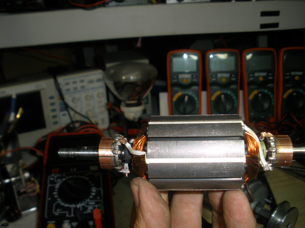
[/IMG]


Regards


Ufopolitics

Last edited by Ufopolitics : Today at 03:38 PM. Reason: Adding Pic
Digg this Post!Add Post to del.icio.usBookmark Post in TechnoratiFurl this Post!Live Bookmark this Post!Google Bookmark this Post!Yahoo Bookmark this Post! share on MyspaceShare on FacebookTweet this thread
Reply With Quote Multi-Quote This Message Quick reply to this message
  #297 (permalink)   Report Post  
Old Today, 03:25 PM
IndianaBoys's Avatar
IndianaBoys IndianaBoys is online now
Senior Member
 
Join Date: Aug 2008
Posts: 304
Quote:
Originally Posted by DadHav View Post
UFO. I can't remember who suggested putting the shaft in from each side, but it can be done. There has to be some careful polishing after though to get the shaft to run smooth in the bushings. I was wondering since an overlap wind produces a high speed motor already would it be worth a try to increase the number of winds on the prototype? The original motor had 70 turns. Would more than 25 turns fit. Here's a video of the double shaft but I think a single shaft would be the best option:
Double Shaft.mp4 - YouTube
John H
DadHav, You executed the suggestion beautifully. You do some great work. I think you will be able to create a real nice motor from scratch as UfoPolitics releases more info and more tests are run. Thanks for sharing!

IndianaBoys
Digg this Post!Add Post to del.icio.usBookmark Post in TechnoratiFurl this Post!Live Bookmark this Post!Google Bookmark this Post!Yahoo Bookmark this Post! share on MyspaceShare on FacebookTweet this thread
Reply With Quote Multi-Quote This Message Quick reply to this message
  #298 (permalink)   Report Post  
Old Today, 03:27 PM
Ufopolitics's Avatar
Ufopolitics Ufopolitics is online now
Senior Member
 
Join Date: Feb 2012
Location: US, Florida
Posts: 579
Awesome work!!

Quote:
Originally Posted by DadHav View Post
UFO. I can't remember who suggested putting the shaft in from each side, but it can be done. There has to be some careful polishing after though to get the shaft to run smooth in the bushings. I was wondering since an overlap wind produces a high speed motor already would it be worth a try to increase the number of winds on the prototype? The original motor had 70 turns. Would more than 25 turns fit. Here's a video of the double shaft but I think a single shaft would be the best option:
Double Shaft.mp4 - YouTube
John H

Great work Hav Dad!!

Well, a double shafted motor we will have super sized ends to do whatever testing is required from "both ends"...grrrrreat!


Thanks


Ufopolitics
Digg this Post!Add Post to del.icio.usBookmark Post in TechnoratiFurl this Post!Live Bookmark this Post!Google Bookmark this Post!Yahoo Bookmark this Post! share on MyspaceShare on FacebookTweet this thread
Reply With Quote Multi-Quote This Message Quick reply to this message
  #299 (permalink)   Report Post  
Old Today, 03:44 PM
ewizard's Avatar
ewizard ewizard is offline
Senior Member
 
Join Date: Jan 2010
Location: Outside the Matrix
Posts: 643
DadHav, RC motors built from scratch - that's impressive. The project here should be a piece of cake for you - especially if you start with pre-built motors. I'm guessing that a lot of people here will be throwing things together in a bubble gum and bailing wire fashion which doesn't always provide the best results. However seeing your video I'm sure you would be doing a much better job. I beg you to have faith in what's been presented here is the real deal and will at the very least be way more efficient. We need someone with your expertise in motors to validate this. You obviously have the talent to create a precision unit and I'm sure you understand the build instructions better than most who have never been inside a motor. If there is even a chance you could make a huge difference for the future generations by providing solid validation of this concept don't you think it's worth the effort? I can see from your vid you are an older gentleman so I understand your concerns in where you spend your time. I'm an older guy too.

Hey I see since the time I started to write this you are already on with building one. Thanks for jumping in!
__________________
There is no important work, there are only a series of moments to demonstrate your mastery and impeccability. Quote from Almine

Last edited by ewizard : Today at 03:50 PM.
Digg this Post!Add Post to del.icio.usBookmark Post in TechnoratiFurl this Post!Live Bookmark this Post!Google Bookmark this Post!Yahoo Bookmark this Post! share on MyspaceShare on FacebookTweet this thread
Reply With Quote Multi-Quote This Message Quick reply to this message
  #300 (permalink)   Report Post  
Old Today, 04:06 PM
john_g john_g is online now
Senior Member
 
Join Date: Jul 2008
Posts: 333
Charging

Hi All/UFO

I was driving my motor this morning with a 6V SLA, and had connected a 12V SLA across the gen output. What was interesting is that the volts on the charging batt was raising but no amps indicated on the amp meter - any one else tried this? I have just brought 2 identical battery's to look into this further.

@UFO
May I ask how you would wind a VW generator armature? I know many here brought these to try and replicate the lockridge device. It has 30 slots. and maybe use 2 pairs of field coils?

Kind regards

John
Digg this Post!Add Post to del.icio.usBookmark Post in TechnoratiFurl this Post!Live Bookmark this Post!Google Bookmark this Post!Yahoo Bookmark this Post! share on MyspaceShare on FacebookTweet this thread
Reply With Quote Multi-Quote This Message Quick reply to this message
Reply


Quick Reply
Message:
Remove Text Formatting
Bold
Italic
Underline

Insert Image
Wrap [QUOTE] tags around selected text
 
Decrease Size
Increase Size
Options


Currently Active Users Viewing This Thread: 75 (44 members and 31 guests)
lamare, ampsvolts, Bill H, Bob Smith, bobfrench@fastmail.fm, BrentA929, charly2, codeboundfuture, Cornboy 555, crazyenergy, DadHav, deslomeslager, Dfortune, Dimension, EpicBlue, hdtbiz, hello_all, IndianaBoys, Itsu, itzon, johnrigh, john_g, kapierenundkopieren, laserjo, MasterBlaster, mrock, Netica, netpoint, no disclaimer, pault, Pmwuk, prochiro, redrichie, Robert McNelly, SammyM, sandy t, shylo, sseti, THZEner, Ufopolitics, wonza, woopy, zapzap, ZeroMassInertia
Thread Tools Search this Thread
Search this Thread:

Advanced Search
Rate This Thread
Rate This Thread:

Posting Rules
You may post new threads
You may post replies
You may post attachments
You may edit your posts

vB code is On
Smilies are On
[IMG] code is On
HTML code is Off
Trackbacks are On
Pingbacks are On
Refbacks are On


All times are GMT. The time now is 11:48 PM.


Powered by vBulletin® Version 3.6.4
Copyright ©2000 - 2012, Jelsoft Enterprises Ltd.
Search Engine Optimization by vBSEO 3.0.0 RC8
2007 Copyright ? Energetic Forum? A Non Profit Corporation - All Rights Reserved