|
|
|||||||
| Homepage | Energetic Science Ministries | User CP | FAQ | Calendar | Search | New Posts | Mark Forums Read | Open Buddy List | Log Out |
| Renewable Energy Discussion on various alternative energy, renewable energy, & free energy technologies. Also any discussion about the environment, global warming, and other related topics are welcome here. |
 |
| LinkBack | Thread Tools | Search this Thread |
Rating: 
|
 Yesterday, 04:12 PM
|
||||
|
||||
|
Different Configurations in Design...Sacred Geometry.
Hello to All,
Now before we have been just connecting Pairs to single elements of Commutators matching "perfect"...like Five(5) Pairs to Five (5) Commutator Elements top-below...Now, it could be done "Asymmetrically" also... Like if We have a 12 Pole Armature...or a 10 Pole Armature... We could use in a 12 Pole Armature, a combination of what I call the "Sacred Geometry Design", where we wind three Pairs of Coils configuring a "Dual Delta Star" or a David Star...now, three Pairs of Coils will give Us exactly Six terminals (Two per Pair) for 12 X2 Commutator Elements...so, it shouldn't work right? Well it does, We just have to "blend" commutator elements in groups of Three, (just wire them up through the hooks)...then we will get Three separated continuous elements per commutator... This will need to do a bit of work right next to each separation of groups of three copper comm elements...open them a bit more the copper, to make space a bit wider by filing them spreading the segment spacing (to avoid heavy arcing, therefore damage to metal plates) The same thing We could do with a 10 Pole Armature...using a Dual Pentagon Opposed, Design...using every two copper contacts joined at each commutator, and we have 5 Pairs of Coils. This Motors have incredible torque, I mean great...but besides that, the times of Charging-Discharging are larger in time of being "On"(charging)...as also at Discharge times, that is why we most file the in-between commutator plates a bit wider. Otherwise they will discharge to next randomly closer element not in "Timing" to be done. [IMG] 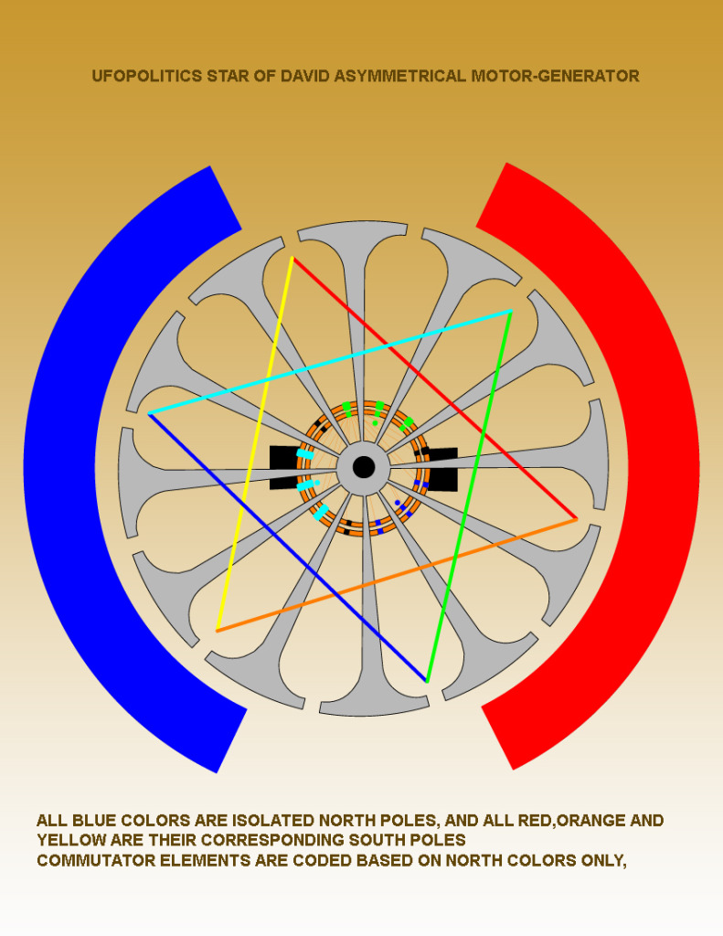 [/IMG] [/IMG]On this particular set-up, Dark Blue (N) and Red (S) are Pair #1 (notice they are Parallel.) Aqua Blue (N) and Orange (S) Pair# 2 Green (N) and Yellow (S) Pair # 3 Regards to All Ufopolitics Last edited by Ufopolitics : Yesterday at 04:24 PM.           


|
|
Yesterday, 05:42 PM
|
|||
|
|||
|
Quote:
Hello ufo The only dc motor i get here is exactly this, a starter for R/C airplanes ... Could this be modified for your type of windings? Do you think there is enough space? I'm new to this... Thanks
|
|
Yesterday, 06:51 PM
|
|||
|
|||
|
Generator Output
Hi Guys,
I would like to confirm my observations with the generator output of the asymmetric motor. While powering the motor through the input connection, any load I connect to the output generator connections causes an increase in current draw from my source 12v battery. Has anyone else noticed this? Btw, I'm getting around 6v on the generator output and 18 volts when using the jumper across the motor input and generator output(As shown by UFO). I was under the impression that the generator output was isolated from the input. If its not isolated what is the benefit of the generator output while running the motor? Keep in mind, I have not run any tests running the asymmetric motor solely as a generator, just in the motor/generator mode. Hopefully Turion will have some data soon on the generator side of things. In any case, this is just the observation of a novice. I just want to confirm if I'm off track or if my findings are consistent with others who have completed the replication. Thank you
|
|
Yesterday, 07:01 PM
|
||||
|
||||
|
Quote:
This is a drawing of the generator mentioned. The left two are the old 6V models not being compatible to the right hand side 12V model. Pic1 Pic2 Pic3 PIC4 Jst got one at ebay: 14V / 32A / 28 bucks.
__________________
Experts spend hours a day in order to question their doing while others stopped thinking feeling they were professionals. Last edited by JohnStone : Yesterday at 07:48 PM.
|
|
Yesterday, 07:04 PM
|
|||
|
|||
|
Quote:
"I connect to the output generator connections causes an increase in current draw from my source 12v battery" What is the amps-volts difference? Thank you
|
|
Yesterday, 07:52 PM
|
|||
|
|||
|
Quote:
 Did you make a mistake with the colors at the generator commutator? I am missing the colors red, orange and yellow. Where does the black spots come from?  Bert
|
|
Yesterday, 08:09 PM
|
||||
|
||||
|
Dear Bert...I knew...
Quote:
The Commutator Elements are coded on Blue Derivatives only ...it is written on the Diagram, below center...didn't see it? Now, it is understood All related South Ends will connect to All Bottom Commutator corresponding Color Codes, as I wrote in my Post below... The Black space at Comm are the SEPARATIONS between joint elements connected in series...That I wrote: MUST BE FILED TO INCREASE THE GAP... Regards Ufopolitics Last edited by Ufopolitics : Yesterday at 08:11 PM.
|
|
Yesterday, 08:24 PM
|
|||
|
|||
|
high guys im new to all this but very interested i would love to try make one of these motor starting small will a 3 armature motor first but not very good at following text instructions has anyone got a video on them making one or a step by step ?

|
|
Yesterday, 08:48 PM
|
||||
|
||||
|
Hello Darkoni
Quote:
Hello Darkoni, Quote:
I mean, this Motors Transfer the Energy and deliver a Mechanical Power out...for free, while supplying an output to your source also...I mean...were you expecting more from this little motor? Ok, and this goes to anyone measuring-testing-loading this Small Motors: Whenever you guys "Add" a Load, please, specify, exactly, to the point,...What kind of "Load" are you trying-stressing out, this "Conversion, Adapt" of Five (5) U.S Dollars and Ninety Nine Cents (0.99) Motors..It absolutely will help...Thanks. Quote:
Did you watch the great video from Mr. Lindemann Motor Secrets? No? Then you should watch it is a great video!..It will give you "Solid Grounds" to be able to Test any Motor the right ways as also to be able to "Evaluate" properly a NOVEL DESIGN..  Yes? Then you should have learned that Effective Armature Voltage (Eff V) in ANY given Motor is given by the Input Values (Source)=Ea MINUS(-)Ec (or C EMF) Are We agreeing up to now?...  No? Then you should watch the video again...  Yes? Then, will you understand that NOW, we are ALL having a POSITIVE VALUE that WOULD NOT subtract ANYMORE in "just"... a pretty short period of One Hundred and Thirty Two Years (132) Isn't that for you... some... maybe, I mean, just a bit of GAIN NOW?... Or you rather do like Symmetry does?...  Because, then you could also make "another test"...grab Negative-Positive Terminals of your Six Volts (+6V) now positive output...and insert it reversed to your Input Values, Source or Ea, meaning where Positive is, insert your negative out, and where Negative is....insert your positive out...then, you may have a "decrease in Amperage"...a weaker and very HOT Motor...but a "DECREASE IN AMPS"...Oh, and do not try to run the "torque" test then...it will melt...  I mean, if that is what you are looking for...go ahead and that easy, it will "solve" the whole "problem" of watching very "Low Amperage"  Regards Ufopolitics
|
|
Yesterday, 09:09 PM
|
||||
|
||||
|
Hello Dear John Stone
Quote:
That looks like a great Machine to convert, now could someone here post me a pic of Above Top View without upper cap, but displaying the brush position, versus stators, and also armature clearance for wiring space...in that diagram can not see it clear.. Otherwise it seems it has room for a second comm... If it has 30 Poles, it is divisible of five (5) and three(3)...therefore, it should work with either of the two first simple designs I have posted...However depends on stator Diameter, angle of brushes, etc...This primary numbers are meant to be expanded into their multiples of...However, they need to be set on CAD, make a Group of all Armature components and rotate it at every degree...with a virtual "marker", to know where you started...What you guys will be looking for is that at ANY point of rotation, Input-Output Coils arrangements COINCIDE AT EXACTLY 180 Degrees, if it does...it is not good, throw combination and try next...and most of times this happens at just Pair of Coils # 1 at Input, then look "WHO" is at your Output "knocking the door" or just touching comm elements... Now, there could be just ONE COIL OF THE PAIR ALIGNED, but if other is NOT, it will work...That creates a different Asymmetrical Magnetic Pattern...not canceling to zero...it configures something like a "Y"... Hope you guys understood me, let me know , please Regards Ufopolitics
|
|
Yesterday, 09:23 PM
|
|||
|
|||
|
hi all
just going on my apprentice schooling and here a pix of my 3 poles modified "Igarashi motor" it works really well The winding is 3 X 100 turns with 0.2 mm copper wire , the same as per my 5 pole replication the torque is really strong and the generator is quite high. i know that all this is subjectiv but it is my feeling so far for more measured resutls , please be patient, or much better replicate and give us details always at full enthusiasm on this project good luck at all  Laurent
|
|
Yesterday, 09:44 PM
|
||||
|
||||
|
About This "conversions" Here...
Hello to ALL,
I want to say this, as you guys understand what we are all doing here... We are "converting" machines that were conceived and designed to run Symmetrically, this means their Rotor (Armature), dispositions of Stators, Brushes and number of Poles arrangement size and separations...were calculated to fit this Methodologies... Now, what we are all doing here, is "picking up garbage, rubbish, junk stuff" not SPECIFICALLY DESIGNED to FULFILL in a 100% BASIS, the WAYS ASYMMETRY REALLY OUTPUTS AND PERFORMS AT MAXIMUM LEVELS... We are all, patching, stitching a very Old piece of sh** Machine...trying to make it run as a V12 Lamborghini...Diablo Figure Out this example... Let's say there is a guy in South America, ...down below the old Continent, that can make "LOOK ALIKE", your OLD CAR, that is a very OLD beaten up, and not functioning right...Volks Wagen...and the Guy tells you to bring several pieces of the same car, ..and He will try to deliver back to You a "look alike" MERCEDES BENZ S600, Convertible...His tooling are also obsolete...old type of Instruments Not Designed to even create a VW...but He likes his job...and hammers that Beetle like thaere is no tomorrow...till He thinks is just like an S600...Then throw a paint job in it... Now, would you expect a perfectly new...MB S600, as just driven out of a German Factory...zero miles...and perform as such? No, right? So, therefore, please, do not expect out of this "Conversions" will deliver a MB... I am playing here the "role" of that guy down south...converting your old VW, broken and beat up...into a stylish state of the art...machine...and showing you how to beat it up... So do not complaint to me please...if you find out that your Mercedes is just a piece of Sh**... Be Happy... , and very "pleased"... that "at least" it runs better than before...when it was a cooking range, and Oil, water -Gas leakier..and tended to overheat every quarter mile...stall and leave you in the middle of the road... that "at least" it runs better than before...when it was a cooking range, and Oil, water -Gas leakier..and tended to overheat every quarter mile...stall and leave you in the middle of the road...So, take it easy...and drive it...and enjoy it. Thanks and regards to all Ufopolitics
|
|
Yesterday, 09:47 PM
|
|||
|
|||
|
Quote:
John H.
|
|
Yesterday, 09:50 PM
|
||||
|
||||
|
Quote:
__________________
Experts spend hours a day in order to question their doing while others stopped thinking feeling they were professionals.
|
|
Yesterday, 09:59 PM
|
|||
|
|||
|
Quote:
May sound a bit off beat, but what about putting the armature in a lathe and dividing the commutator into 2 equal sections by cutting out a central ring - thus 2 commutators. Then drilling small holes, inline with the shaft through the commutator insulation, below each bar, to then allow connection to be made? Regards John
|
|
Yesterday, 10:07 PM
|
||||
|
||||
|
Where Tf Is The Witch???
[IMG]
 [/IMG] [/IMG]
|
|
Yesterday, 10:11 PM
|
|||
|
|||
|
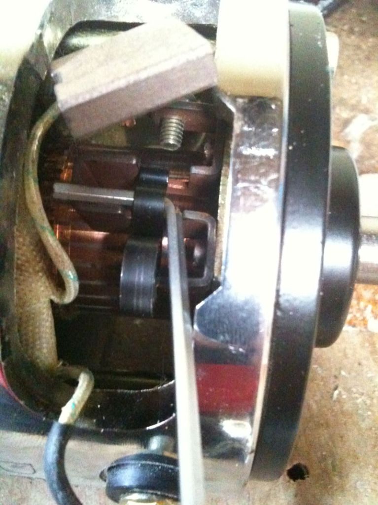
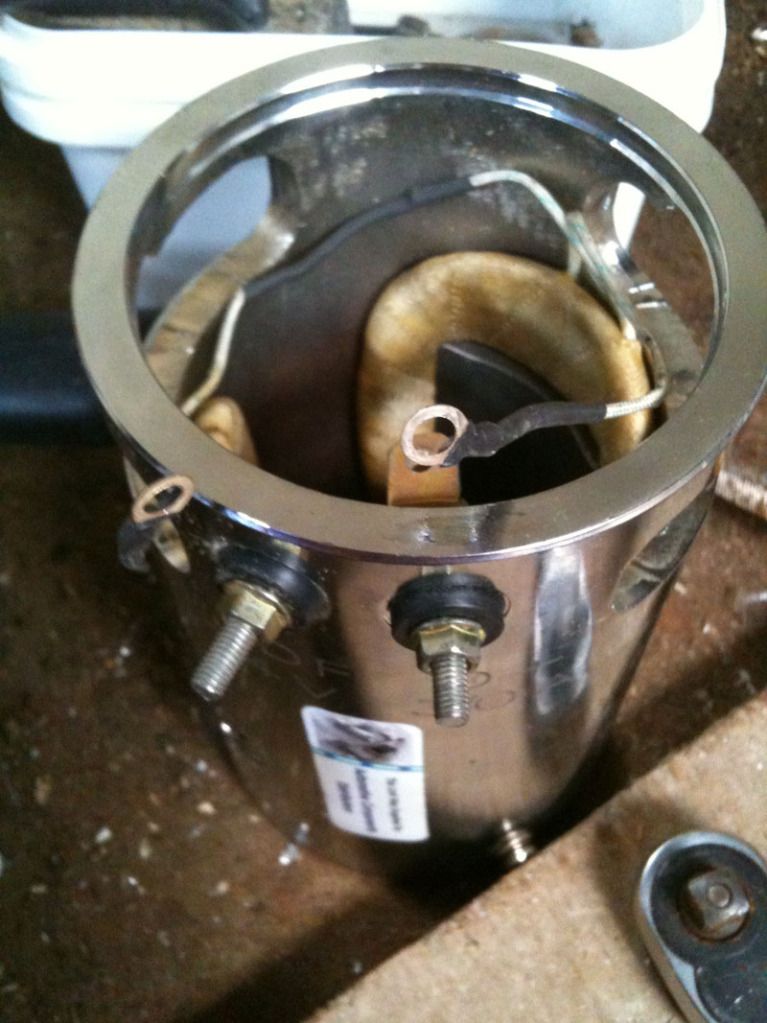
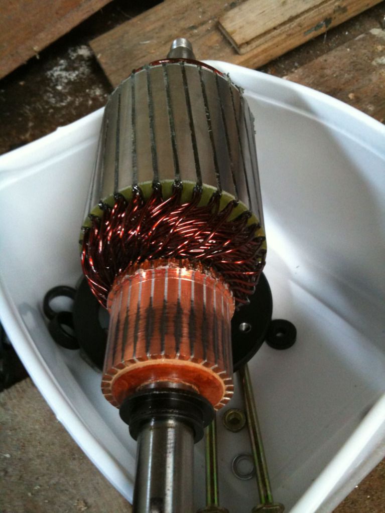
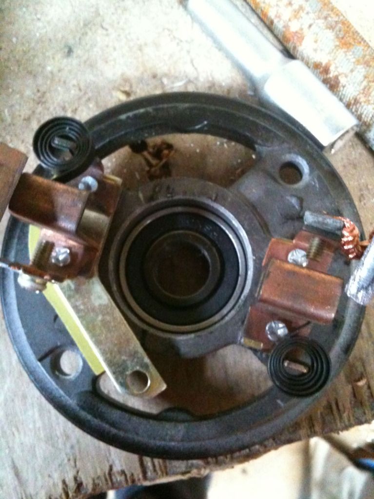
Trouble-shooting 3 Pole Conversion
Hi Guys,
I have 2 nice 5-pole DC motors to convert. First, I thought I'd try 2 cheap 3 pole motors from 2 identical dollar store toys. I wired 'em up as per UFO's specs, modded the housing and put the commutators at each end. But no movement at all, even with a 9 V battery. I thought it could be: - rotor stuck against a stator magnet (should I grind rotors it down for more clearance?) - magnets reversed/backwards (is this possible?) I'm bummed out; thought I had this in the bag. I can post pics as well. Any troubleshooting suggestions appreciated. Otherwise, I'll start on the 5 pole. Bob
|
|
Yesterday, 10:28 PM
|
||||
|
||||
|
Hello Dear Bob
Quote:
Hello Bob, What does it do?...it "Humms"...or just absolutely noting happens? It does a huge difference in this answer being Y/N Check the motor for rotation freedom...is it moving?...beside magnetic pulse feeling...it does move? If it would be touching a magnet it will make a noise...a different sound... Possible faults 1- Commutators not aligned in a linear fashion and/or at the ANGLES related to Armatures POLES, as indicated in Drawing... See Bob...the Commutator spaces and the contact elements create a pattern, either one (gap or metal contact) should line up either with very center of Pole or Gap between Poles...and that relates to BOTH COMM. Make sure you do not have an inverted winding...it will humm but won't move... Don't move to 5 yet...it is more complex...let's fix this one... Regards Ufopolitics
|
|
Yesterday, 10:39 PM
|
||||
|
||||
|
Connection with Edwin Gray machine?
Hi all,
Just posted a comment on the Gray tube thread: Gray Tube Replication It may be that Ufo's work finally enables us to unlock Gray's secret. If Gray indeed used the same magnetic principle in his motors to get COP>>1, then it may be very interesting to experiment with Ufo's design in combination with pulsed discharge of high voltage capacitors, be it relatively low voltage (several 100 Volts) trough semiconductors, or high voltages trough spark gaps. In the case one wants to work with spark gaps, one may consider using triggered spark gaps, a.k.a. Trigatrons: Gray Tube Replication Trigatron - Wikipedia, the free encyclopedia Quote:
The idea is that the strength of a magnetic field created by an electric current depends on two factors: 1) the current going trough the coil; 2) a sudden change in the electric field. This originates from the well known Maxwell equations: Maxwell's equations - Wikipedia, the free encyclopedia Quote:
So, both this Maxwell principle and Gray's stuff suggest that you can get some extra (magnetic) bang for the buck by using (relatively) high voltages in combination with fast-swithed pulsed discharges from a capacitor (bank). If you want to experiment with this principle, you would need some way to trigger the discharge at the the desired angle in the rotation cycle of the motor. It should be possible to mount a dish with a number of holes on the shaft and then use a slotted optical switch ( Slotted optical switch - Wikipedia, the free encyclopedia - often found in computer mouses ) to get a trigger signal. This is just an idea which may be interesting to experiment with... Today, I have ordered two of these motors for a replication attempt: Igarashi n2738-48gf buy now - Conrad Electronic SE Multipurpose electric motors Electronics Online Store There are also 5 pole versions: Igarashi n2738-51g-5p buy now - Conrad Electronic SE Multipurpose electric motors Electronics Online Store I chose this one, because it appears to have a reasonably long shaft. Update: Had a night's sleep over this... Of course it is obvious that you can discharge a certain amount of energy either quickly or slowly. If you want to discharge, say, 1 Joule of energy within 1 micro second, you need a much higher voltage and current than when you want to discharge the same amount of energy within a second. Leedskalnin's experiment suggests that it is possible to "lock" a magnetic field inside a(n almost) closed magnetic loop and thus you can in principle create a much stronger magnetic field for the same bang in terms of energy by pulsed (short duration), high voltage, high current discharge instead of using D.C.. More on the Gray thread: Gray Tube Replication
__________________
Please donate to Eric Dollard All of Eric's posts here together on one page -:- Electrical Engineer disproves Einsteins Relativity Theory Who performs the first longitudinal Moon-Bounce in history? Mark McKay Documentation on Edwin Gray's Fuelless Engine Patent collections: Gray Meyer -:- Everything I have posted on this forum of which I am the author, is hereby part of the public domain. You can do whatever you want with it, except claiming that you're the author of it. -:- Last edited by lamare : Today at 06:59 AM. Reason: More info 
|
|
Yesterday, 10:52 PM
|
|||
|
|||
|
Center coil connection
Quote:
Window Motor Runs Window Motor. - YouTube You will see much more stuff on the output running at more voltage than the input. But this is still not over unity no matter what the COP on a piece of paper says. The young experimenters here and on most other forums are looking for something they can see in reality. Over Unity = Self Run or Charging several batteries from one. If your over unity is only on paper then you need to explain this to everyone who is following you here. Here is a video for the benefit of the two inventors who did the generator test and it may also interest others. This is a video that I was going to save to show how much better the modification was but now I can see I wont need it for that. http://www.youtube.com/my_videos_edi...=VwRmkYhxqX E That's right I was going to try the same test the others did and I may have even encouraged them so I'm the one who should take it on the chin not them. John H
|
|
Yesterday, 11:03 PM
|
|||
|
|||
|
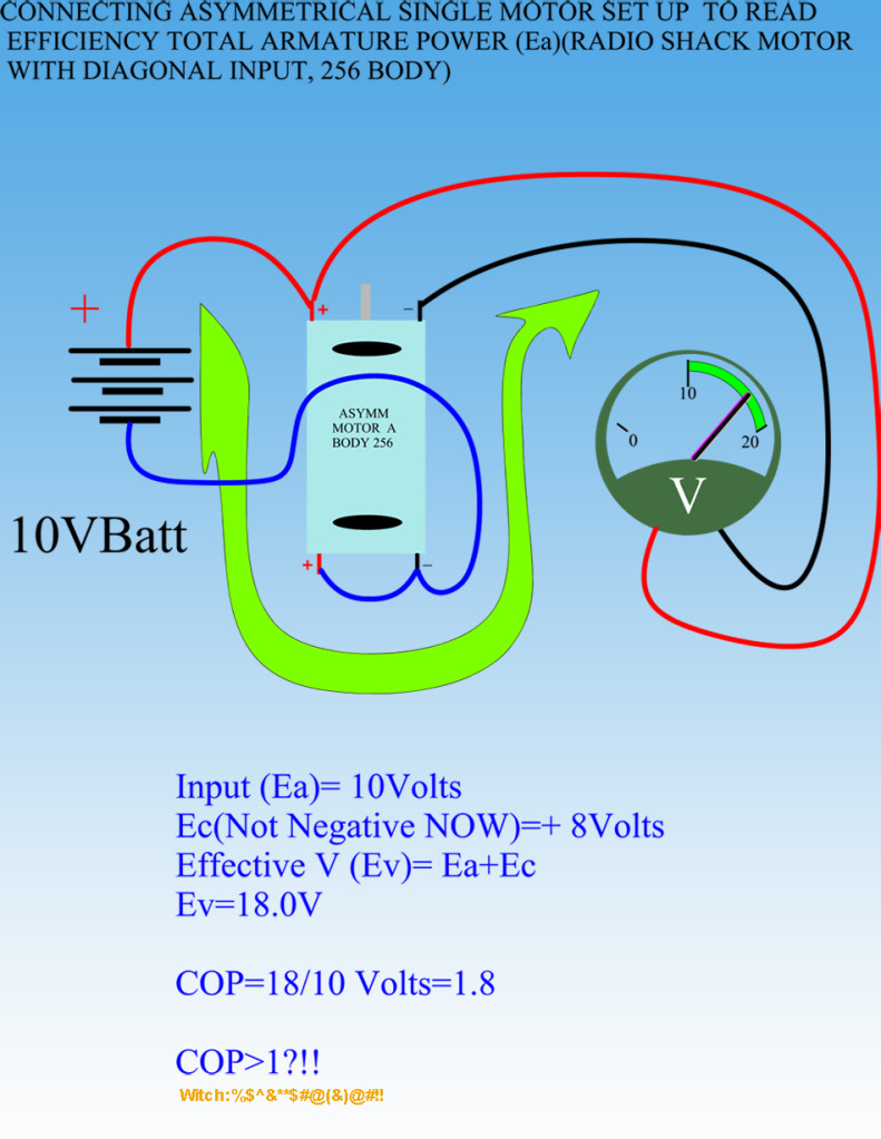
Not how you calculate COP!
Quote:
Your output voltage is only 8 volts anyway. The way you have it drawn you are adding the battery voltage to get the 18 volts. So 18 volts is not your true output. The last time I asked questions or commented about your circuits you proceeded to just call me names. This time would you please address the technical issues I have raised and forget the name calling. Respectfully, Carroll
|
|
Yesterday, 11:03 PM
|
|||
|
|||
|
Bob Smith
If your motor makes just a hum, you must find the bind in motor. It must turn freely and aslo when you move the shaft back and forth in the motor you want just a little play and a free "feel" of movement. If no hum, take your contact testor on the + and - tabs on one side and turn the rotor by hand. You should get electrical contact all the way arround but with a tiny skip where contacts change. Do the other side as well. If nothing or a skip in the pattern your brush patterns are not lined up. Even if one coil is shorted, you should get a hum. My guess is brushes are not correct allignment.
Dana
|
|
Yesterday, 11:25 PM
|
||||
|
||||
|
Ok, so heres my take on the de-witching:
And I will not speak on efficiencies since I believe UFO is not finished showing us his work. I will say however, for under 100mA this thing puts out some serious power for a toy motor. enough that I will continue to work with it through hooking up a generator, maybe not close the loop but show watts in vs watts out. Now... Thank you UFO for the explanation above, that is helping a mushy brain like mine get up to speed. Taking only one coil as you note, the coil via commutator connects across the battery charges, and begins to oppose the magnet it then is pushed over toward the next magnet where it gets sucked in. this is basic so far. So now the coil is charged and would normally start the lenz/witch process of fighting the next magnet, however what happens very quickly is this coils commutator connects with the next brush and for ever so briefly is connected in parallel with another coil, this other coil takes the discharge from our first coil and uses it to push away and suck in on the opposite side giving us another push/pull for free at quite a higher voltage or you can take that charge to a cap etc and use it for something else. ????????????????????????? Please let me know if I am way off base so far . Here is my lame vid: (should be completely uploaded in 5 minutes according to u-tube De-Witched UFO Motor - YouTube My little motors untouched draw 2.5 amps off 6 volts and garnish 13,000 rpm My De-witched UFO motor draws 50-90mA and gets to the same speed. I have no luck getting more than 2 volts off the charge side, but am very pleased with the upgrade in performance. gotta run, Patrick
|
|
Yesterday, 11:32 PM
|
||||
|
||||
|
Finished all the testing on the standard motor setup.
Radio Shack model 273-257 9-18 volt DC motor 1.98 Amps max With the motor connected to another motor it showed 12,204 RPM at .82 amps running on 12.3 volts The output of the second motor (under the load of the bulb) was 7.2 volts at .7 amps lighting a Sylvania 211-2 Bulb rated at 12.8 volts 12.4 watts When that bulb was connected as load, the RPMs of the motor decreased to 10,200 at 1.4 amps and 12.3 volts. So. The basic motor with a second motor attached runs on 10.08 watts under load (with light connected to generator) it runs on 17.08 watts while producing 5.04 watts. Can we all agree that this is an accurate method for determining what the motor is producing? Because these are the standards of measurement I will be using when I test the converted motor. The conversion motor showed 14,462 RPM's but when I went to check the amp draw, I got some really irregular readings. I disassembled the motor and discovered that my second commutator had rotated slightly on the shaft, so I have they epoxy drying now, and will post the data when I have a chance to run it again, which may not be until the morning. Meanwhile, I will be assembling another motor and generator. I can say for sure that the RPM's of the motor are higher than the standard motor. Just the facts ma'am. Sorry I don't have ALL the data to report, but this is the kinda crap you live with doing this stuff, and I am pretty careful about making sure things are working correctly before reporting incorrect data. Dave
__________________
Talent hits a target no one else can hit; Genius hits a target no one else can see. - Arthur Schopenhauer Get it all on record now - get the films - get the witnesses -because somewhere down the road of history some bastard will get up and say that this never happened' General D.Eisenhower The world we have created is a product of our thinking. It cannot be changed without changing our thinking. Albert Einstein I aim to misbehave. - Malcolm Reynolds Last edited by Turion : Today at 12:56 AM.
|
|
Yesterday, 11:44 PM
|
||||
|
||||
|
Hello Dear Carroll
Quote:
Hello Dear Carroll, Quote:
Please, may I ask where did you read, in what part, did I write the word..."Total Output=18 Volts"? A Motor Armature Power is given by Ea-Ec=Effective Voltage (not output) Effective Voltage is our Rotor Voltage Power, given by Counter EMF, which, since it is a reverse value to our Input...is then subtracted..to our Source Input...are we right til now? In Peter Lindemann is very simple deal, He gets in 12.1 V...and C EMF is -9.0V This if we use very simple math gives Us a Voltage value of 3.1V...are we ok to here? Then we have an Ev (Effective Voltage)...not Total Output, Carroll, of 3.1 Volts as Armature Voltage Power...right? Ok, Dear, so then, I will let you "Calculate" My Motor math as Ev amount (not output)...How much, do you think that is? And remember I mean Effective Voltage, not Total Output You tell me... Now COP, derives from Ev/Ea, meaning Effective Voltage divided Input Voltage...In Mr Lindemann's video, it renders a COP of 3.1/12.1=0.256 Whenever you finish doing this math...then we could calculate my COP properly then... I do not know why we are all arguing over something so simple...if we would be talking about Maxwell's Quaternions Formulas...I would understand, or even High Level Algebra ...but...not in so simple math... Regards Ufopolitics
|
|
Yesterday, 11:49 PM
|
|||
|
|||
|
the real witch
This is excellent info
You have to get rid of the steel core(the real witch) Magnets like steel(bad witch) And running electrons creates magnetic fields Is the field that is created chopping off the witches head?? When does the opposing field come into play??? UFO, Thank-you for sharing In the video when you put the pliers against the motor , I noticed the drop in readings,If you are capturing the back emf , shouldn't you get a bigger back emf kick , because your drawing more power through the coil???I'm not an electronics type ,I'm more hands on building stuff.. Not scared to hook things up wrong shylo
|
|
Yesterday, 11:52 PM
|
||||
|
||||
|
Is Ok Turion
Quote:
Hello Turion, Shut happens man...now may I suggest to do this...before inserting new commutator...get the area of shaft length that will house the comm, and JUST in that area, use a small little chisel, or flat screw driver that have metal backing to be used as a chisel...and leaning against a press, hit a bit to create some small splines or even some small indentations on shaft metal...not too hard though...that will avoid Comm to turn ever again... Regards Ufopolitics
|
|
| Currently Active Users Viewing This Thread: 78 (44 members and 34 guests) | |
| lamare, barbosi, bkangus, Blue_Serge, BrentA929, charly2, citfta, codeboundfuture, Cornboy 555, DadHav, darkoni, delper, Dfortune, GlenWV, gsmsslsb, iankoglin, IndianaBoys, John_K, jrspath, kapierenundkopieren, laserjo, MasterBlaster, mikec_ut, mklimesh, mrock, phrao, prochiro, RaptorGus, ridlemeone, Robert McNelly, SammyM, sandy t, sebosfato, sturgeon, Stylianos, Turion, Ufopolitics, wonza, woopy, yaro1776, zapzap |
| Thread Tools | Search this Thread |
| Rate This Thread | |
|
|


 [/IMG]