
 |
|
|||||||
| Homepage | Energetic Science Ministries | User CP | FAQ | Calendar | Search | New Posts | Mark Forums Read | Open Buddy List | Log Out |
| Renewable Energy Discussion on various alternative energy, renewable energy, & free energy technologies. Also any discussion about the environment, global warming, and other related topics are welcome here. |
 |
|
|
LinkBack | Thread Tools | Search this Thread | Rate Thread |
 Today, 06:15 AM
|
||||
|
||||
|
My Asymmetric Electrodynamic Machines
ASYMMETRIC ELECTRO-MAGNETIC ROTATING METHODOLOGY FOR MOTORS AND GENERATORS ASSEMBLIES.
ABSTRACT A new concept to the Art of Electromagnetic Rotation Methodology, that includes new structuring of the Mechanical Architecture of an Electric Motor and/or Generator or combination thereof, extending to the methods for processing their Input-Output governing data. Static and rotational components, particularly individual isolated groups of coil elements performing dual functions as a Motor and as a Generator at specific angles within the 360 degrees of rotation. An specific and unique feature of this methodology is the non reversal of the input current-voltage polarity within the actuating individual isolated coils during the motor stages, causing a non changing magnetic field pole projection due to a one sense or direction magnetic flux in their respective cores, rotation occurs by switching intervals of On and Off Times at specific positioning, such that a repulsion and/or attraction is constantly obtained at T-On, of individually orderly sequenced North-South poles. This particular switching times On and Off creates a one direction, non colliding electronic flow within the isolated conductive coil elements deriving into a pulsating current dropping to zero (at T Off) to Max V in (at T On), equivalent switching codes as to the electronically controlled Pulse Width Modulation (PWM) utilized to control the current feeding input in Electric Motors and the Input-Output parameters of Power Source Converters, this identical Data-Transfer, based on Pulsed Signals, establishes a common language of operation between machine and input-output control commands, leading into a robust communication protocol. The advantages that comprises a Motor and/or a Generator driven directly from the core by pulsed signals, extend to the incorporation of Optoelectronic s as to replace the Old Fashion, brush-commutator switching systems by an emitting pulsed width modulated (Infrared PWM as an example) or linear optical signal (Signaling steadily where On Off occurs by mechanical-magnetic loosing angle of interaction) to an Optoelectronic receiver connected to the Power Switching Executing circuits, delivering a less friction, low noise, more accurate and precise communication Network. ASYMMETRY TO ENLIGHTENMENT - YouTube A more detailed explanation will follow, as also some videos of working models... Regards and get ready... Ufopolitics Last edited by Ufopolitics : Today at 06:37 AM. Reason: ADD IMAGE           


|
| Sponsored Links |
|
Today, 01:55 PM
|
||||
|
||||
|
Thankyou, Tesla would be proud
Hey Ufo,
Thankyou for continuing to share all your knowledge via open source and that action has never been lost on me  I think it's best for me to watch this a few times and process the information before I comment my friend. I have so many ideas/expectations for this clip and very eager to finally answer my fundermental questions about Radiant energy production the way I see it. Clarity to define the Asymmetrical concept to energy flows is pivotal!!! Regards Zero 
|
|
Today, 03:02 PM
|
||||
|
||||
|
My Bosch Motor Converted To Asymmetric
Hello to All,
To show you guys...that this is not only CGI Animations...but also Real working Prototypes...here is my Bosch Motor pictures with dual commutators and already wound...also already mounted in a Badsey Scooter...This motor could run myself...at high speed with just three R/C LiPo's...for very long times...I can carry an "Extra Pack" in my pocket...  [IMG] 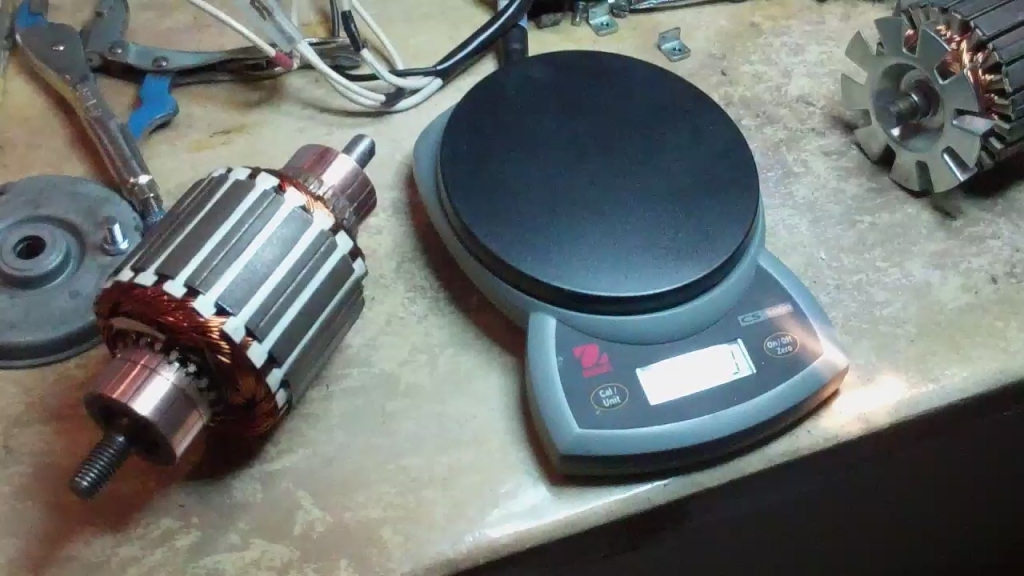 [/IMG] [/IMG][IMG] 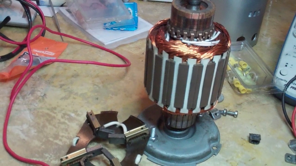 [/IMG] [/IMG][IMG] 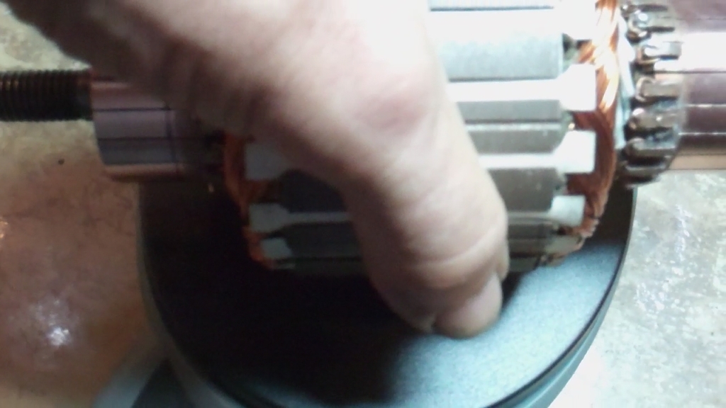 [/IMG] [/IMG][IMG] 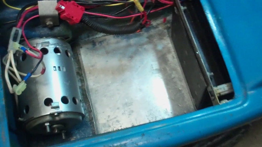 [/IMG] [/IMG]
|
|
Today, 04:13 PM
|
|||
|
|||
|
@ufopolitics:
Wow! That is impressive workmanship. Will your "part 2" have some basic DIY instructions and/or measurements for input VS output, etc? truesearch
|
|
Today, 04:30 PM
|
|||
|
|||
|
Thanks a lot Ufoplitics for sharing your knowledge, it really opened my mind.
. I had to seen twice the video to got it.In the video at the minute 11:30 you show the input and the output, I have a question in this point. How would be the conection of the right side (output) with the left side?, Best regards.
|
|
Today, 04:32 PM
|
||||
|
||||
|
The Five Armature Pole/Radio Shack Motor
Hello,
Here are some pics of what you will do with this little RS Motors... The reason I chose this particular one, is because it is simple to take apart, the shaft length allows the installation of a second commutator (this is very important feature to any motor to be converted without making a clever project!) So, one motor will have to be "sacrificed" to build one...this is the draw back of this...however, larger models that supply separate replacing parts will work great without buying two motors...which could become very expensive. The sacrificed motor we will take off the commutator, very easy and smooth operation...it is attached to shaft and secure through splines built on shaft...cut wires, and clean extra resin from clearance with blade to see exact gap between comm and upper armature core resin...to start pulling it apart exactly from there. if you push commutator from elements or mica base...you will crack it, or separate Duck Tail Copper element...Comm is ruined and goodbye 6 bucks... The next step would be to cut the frame smaller ring off the sacrificed motor...that will support the second commutator brush housings at the "Asymmetric one to be". Now you will have to make exact measurements here, however this motor gives us a pretty exact line to be cut right below the brush oval window ..careful, you could throw out $6.00 in seconds...it must be filed down to exact spec's, then take out the Magnets springs that hold them together...pull magnets out and weld frame...no heat to magnets!!...it could ruin them. Besides it is much better to test rotation to be freely spinning before welding it together, use some crazy glue as "tack welds" first...till you get it right. I will give exact millimeters ring size further, I can't now... I will also post the procedure of windings, I used 30 awg wire (Radio Shack Red Wire), 25 turns per coil...so a Pair will have 50 turns and should read around +/- 1.2-1.4 ohms. Now, this motor uses a type of winding I call the "Pyramid Shape" (You will love the "Sacred Geometry" ones coming soon) However, this pyramid type is meant to be expanded to odd pole numbers. Pyramid because the two coils (Serial connected Pairs) configure an open V, where the "point" where the two lines converge will be your indicator to each pair center, each coil winds exactly as being just one angled coil, in order to have one side of Pyramid N, and the other South. You must decide which end of motor would be your Positive input/start side, it would be your marker to wind, so mark it, color it, I normally use the longer shaft part where we mount the extra commutator. And each Pyramid point would be your coil pair number. This motor needs Five(5) Pyramids, meaning, Ten Single Coils (10). All Coils are wound exactly same direction, and try to keep them "balanced" by exact number of turn. One of the most important part is to set the commutators elements exactly linearly aligned upper and bottom...in order that upper-low brushes will make EXACT timing contact per segment-per coil pairs. The second very important part would be to load the whole diagram in a CAD Software and rotate to see exact angles of contact in further to come more complicated models with more poles...The positioning of brushes related to Stators is VERY IMPORTANT, as where you have connect to commutator element!! Later on (and I love this feature to verify contacts from already assembled motors-generators on this systems), is the fact that with a digital meter on continuity set mode, connected to Upper Positive to lower Negative (Motor Input), you could check each pair of coils timing and contact, by slowly rotating the shaft...as further on is a great way to detect any open coils for repairs... Below are some pic's of the model building it... This little motor, will brake the Symmetry...it could run linear (attached directly to a 10-12V Battery (not a car battery please!, I have not tested with too high amps!)...If you input 10V, it will shut straight off the two outer flow end terminals around 5 to 8 Volts 9 (because of resistance and commutator losses)... However, if you attach (like I mention on Asymmetry Video)...the two bottom terminals positive output with negative input Still feeding lower negative...and attach a meter at upper positive input, and upper negative output, we will be connecting Input battery with extra output out in series...then we get around 15 to 20 Volts, depending on RPM's and under load it increases output voltage-current. Pleaserealize that also a mechanical energy is being generated,...and with lot's of torque!...Try to stop this little motor...and you will be very surprised... However, when pulsed by an oscillator, since it is getting an interrupted signal...it will produce more...and the more you accelerate it...the more it gets out... There are ways to connect it as a SEPIC Converter circuit (Two Inductors DC-DC Single Electromagnetic Primary Inductance Converter)...I call it the SEPIC MOTOR...Where Inductors are no longer just sitting in a circuit board...but performing also a mechanical output. Regards Ufopolitics [IMG] 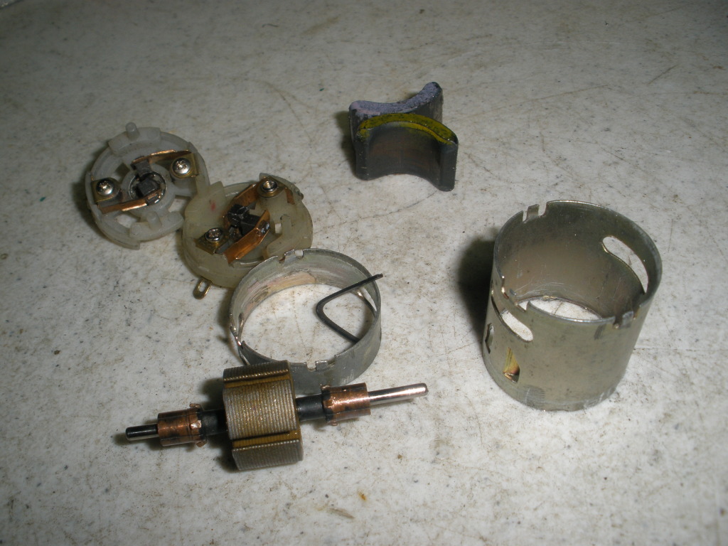 [/IMG] [/IMG][IMG] 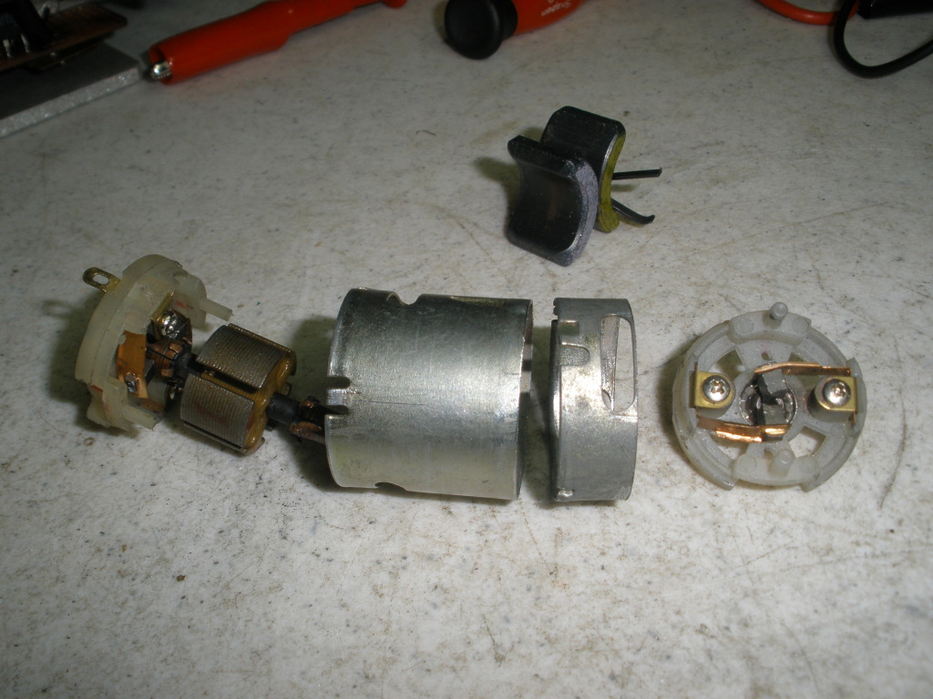 [/IMG] [/IMG][IMG] 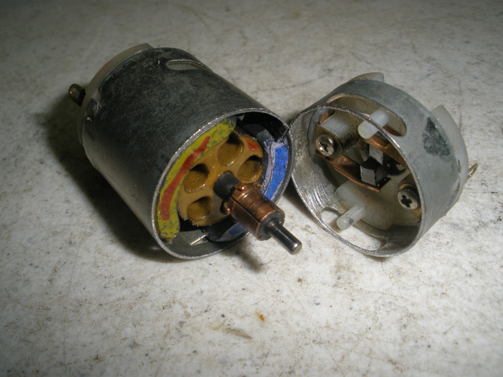 [/IMG] [/IMG][IMG] 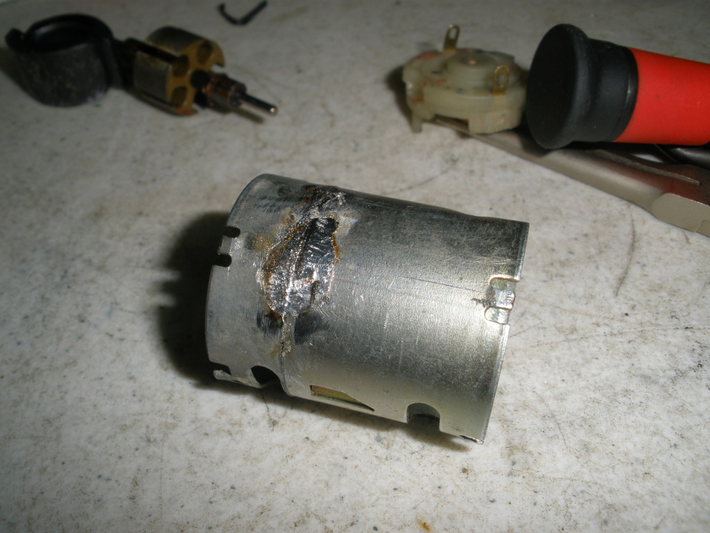 [/IMG] [/IMG][IMG] 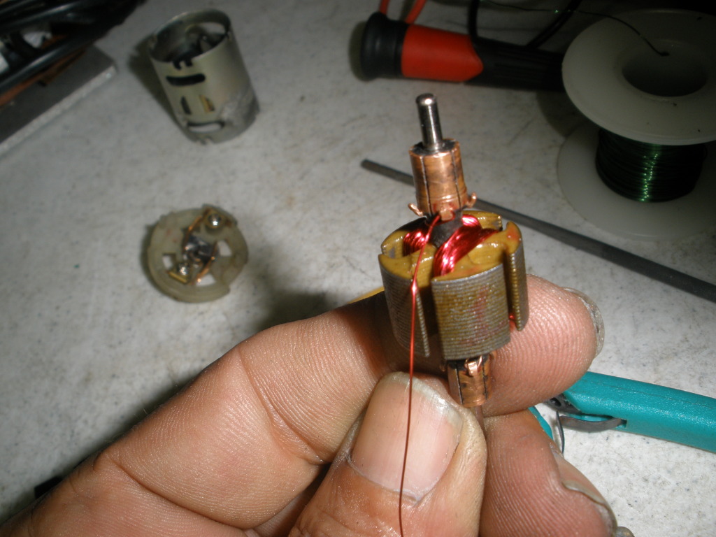 [/IMG] [/IMG][IMG] 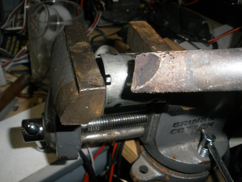 [/IMG] [/IMG]Last edited by Ufopolitics : Today at 09:36 PM.
|
|
Today, 04:36 PM
|
||||
|
||||
|
How to coming...but take it easy on me please...lol
Quote:
Yes I will..in time...I am still taking a little rest from long video editing-making... So far below you will find the Radio Shack some instructions on making it... Regards Ufopolitics
|
|
Today, 05:53 PM
|
|||
|
|||
|
I already have some of this wire, will that work ok?
When you say weld, will a standard soldering iron suffice, or is some arc welding required? Can these devices be self-running with no outside power? (even if an initial input is required), by somehow connecting the output back into the input.  Last edited by wonza : Today at 06:44 PM.
|
|
Today, 08:34 PM
|
||||
|
||||
|
Hi folks, Hi ufopolitics, thank you very much for sharing your work.
I comprehend how you have the 5 pole armature coil wound with the 2 stator magnets. So this arrangement allows more of our input voltage to charge the armature coil to create a magnetic field, instead of the usual symmetrical counter emf loss plus commutator loss, which destroys at least 75% of our input voltage. What is the percentage of input voltage loss due to counter emf with this pyramid-V coil pair style geometry, or is it more a case that it aids rotation. I'm still trying to fully comprehend how it either prevents much of the typical clashing of induced counter emf or aids our input voltage. Gotta go to a birthday party, though later, I am going to draw this on CAD, so I can rotate it and see things better. I seem to recall, Robert Adams designed an asymmetric design like this also. Thanks again. peace love light tyson  
|
| Sponsored Links |
|
Today, 09:38 PM
|
||||
|
||||
|
Wrong Gauge at 5 pole Radio Shack description above, I fix it now
Hello to all,
The awg for this little motor is 30 gauge...Red wire from R/S...not like I wrote before 26, which is the Green wire... Regards Ufopolitics
|
|
Today, 10:18 PM
|
||||
|
||||
|
The way it works...
Quote:
Yes you got it right basically...but let me clear some small clouds... We provide Source to Input, energized Pair of Coils build a "per-conceived" magnetic field that would be immediately attracted repulsed away from original positioning, Coil will disconnect from source, and will travel free...separated from original brush contact...here, in this nano seconds...it will build an opposed magnetic field, therefore an opposed voltage potential (just like the Inductor does at the Booster-SEPIC-Buck Converters, that is why I spent hours building the 3D Graphics of the Inductor part at my video...lol)...Inductors, as my Coil in my first Thread...build an opposed magnetic field provided by Radiant....The "Princess"... . I have much better proof of that fact, coming soon...well not too soon...but coming.When Coil reverses magnetic polarity, it happens exactly at a point where it will assist rotation...(And here you guys could understand Joe Newman statements, as well as many Free Energy Inventors...that their motors used the C EMF to "assist rotation" which did not make sense to anyone..but I did understand what they meant... You have to realize that Symmetry creates the Counter Effect, by providing an inverse Input to Source...that is NOT the normal reversing that occurs when Coil is interrupted... or Inductor in a booster circuit board...Symmetry KILLS the Natural Counter Effect, by creating a fake one with Hot electricity...The Natural Radiant Counter Effect will never get out ever...unless we FREE those Coils at least a small portion of the time... Resuming, We are using the Commutator Switching, just as an Electronic Oscillator Switcher, but mechanically operated...So, Charged Inversely Inductor will travel to "Delivery Brushes"(Output) where We collect it... You Guys need to get "Familiar" with The way SEPIC Converters work...I could not do it on video because of time... But a SEPIC is a Dual Inductor Converter...it performs a Charge-Discharge Alternatively of both Inductors...through a Non Polarized Cap between the two Inductor legs connected to output...I have done exactly same connections with my motors...except the Inductors are also performing a Mechanical Rotation (using their swapping magnetic fields) A CUK Converter is more complicated function and it "inverts the output",so it is NOT a good example for this understanding... And Yes, We do "Add" and not subtract the Input to Output Values...they are not opposed anymore, but on our side...therefore: Ea (Input) and (-Ec) (Counter?)..NO MORE, it should be written as Ef (E forward), and have a + sign in front...then it will be: Ea+Ef=Ev (Effective Armature Voltage)...disregarding R to One Ohm (1.0) I hope this explanation made it a bit clear...hope so... Regards Ufopolitics
|
|
Today, 10:55 PM
|
||||
|
||||
|
UFOpolitics, Many thanks again for sharing this incredible info. Do take a good long rest and then some. You've earned it. That will give the builders here time to round up some parts and time to put together some good questions.
I've sent a message to a person who I consider to be a master motor builder who has been involved in overunity work for well over a decade. Hopefully he'll join in here. I know he's aware of some of these concepts and has done a lot to bring awareness of coil shorting to collect back emf. I expect he would be one of the first to get a useful replication built based on these ideas if he checks in here. I like to jump in to something bigger than radio shack toy motors if I think the concept is good and I think this is good to go. Can you recommend a particular motor(s) that would be good to work with and which would have enough power to drive a scooter at least? I think motors with dual commutators are somewhat of a rarity as far as finding them right out of the box aren't they?
__________________
There is no important work, there are only a series of moments to demonstrate your mastery and impeccability. Quote from Almine
|
|
| Currently Active Users Viewing This Thread: 21 (14 members and 7 guests) | |
| lamare, charly2, Cornboy 555, diegoviz, ewizard, JohnStone, kapierenundkopieren, pmazz850, prochiro, RaptorGus, realmikel, smoky, xavier1333 |
| Thread Tools | Search this Thread |
| Rate This Thread | |
|
|


