Tesla's Aerial Machine
Aeronautical and inter-stellar propulsion
A Tesla Motor
"the flying stove"
The Tesla "flying stove" Space Drive
"I am now planning aerial machines devoid of sustaining planes, ailerons, propellers, and other external attachments, which will be capable of immense speeds" - Tesla's autobiography, "My Inventions." To a Westinghouse manager, Tesla wrote "You should not be at all surprised, if some day you see me fly from New York to Colorado Springs in a contrivance which will resemble a gas stove and weigh as much. ...and could, if necessary enter and depart through a window." - TESLA: Man Out of Time, by Margaret Chenney, pg.198
Tesla intended the world to have a free, wireless, source of power "My power generator will be of the simplest kind - just a big mass of steel, copper and aluminum comprising a stationary and rotating part, peculiarly assembled."
According to museum officials at The Nikola Tesla museum in Belgrade, "he left sketches of interplanetary ships. This information, however, has not been made available to western scholars." - again, TESLA: Man Out of Time, pg. 203
From my previous section in "Part One," and from trying our best to figure out what Tesla was trying to create, we know he intended to build a Flying Machine. It was the product of his dreams, and, his life-long passion. We know that Tesla invented many things which no one else has been able to duplicate since. He spoke of even more which he intended to do but never got around to. There are many books written by people claiming to have some of this, and or other, information. "Tesla, Man of Mystery" is one of those books. Along with general information on Tesla and a few fables, there is one diagram and enough information about it, for us to duplicate the device. They call it the "Tesla space Drive". It may be the heart of what Tesla said would look like flying on "a gas stove" and is "peculiarly assembled." (above): The Tesla Space Drive - click to enlarge image. Here comes fellow engineer Greg Smith's take on Tesla's Flying Machine...this is one of the most original, brilliant pieces of work that we have seen in our twenty plus years at reverse-engineering of the Tesla systems.

Diagram from page 31 of Tesla, Man of Mystery © 1992
Chapter 4: "The Tesla Space Drive"
According to Greg: I found the machine easy to build, the rotational speed needed was not so easy. "The first step in developing this system is to cause a counter-clockwise (sense chosen arbitrarily) acceleration of the center of mass of the four eccentrics (refer to diagram) in a circular orbit about the X axis... there is a common point about which the center of mass of the eccentrics and the center of mass of the device as a whole gyrate." pg.32, "Tesla, Man Of Mystery."
"The reaction to this angular acceleration is a linear acceleration along the system axis (X) and directed outward from the page. ...this system functions in accordance with the right-hand rule. ...[ It will ] wobble noticeably at low thrust levels. This effect fades out, however, as the thrust is increased." pg.34-35
Compliments: Greg Smith, Pompano Beach, Florida. To continue; My first observation is that it is a set of 4 spinning weights arranged on a frame "peculiarly assembled" as Tesla said. It is so simple (easy & cheap!) to build, and yet, it does something Phenomenal. The object is not spinning nor do any one of the spinning weights match the orbit of the object (frame) and yet, the mass of the object is in orbit. Like electrons in orbit in a stationary coil - an area in which Tesla is already famous. Instead of acceleration by the left hand rule, now it is by the right hand rule. Even that makes sense. No one seriously interested in a new, cheap, source of propulsion need question or dispute anything, just build it and see what happens. If you can put enough speed into it.
Collectively, the center of orbit of the four "eccentrics" defines a circle for which the center point is the center of mass for the frame the eccentrics are built on. The direct approach is to build the device symmetrically about the center point: with a top as well as a bottom. Nothing is mounted on the base. The 4 eccentrics must be able to spin. They are mounted above the base. Everything is mounted between the top and base plates: "...there is a common point..." which won't exist unless the unit is symmetrical. It needs a top plate to keep it as rigid and as light weight as possible as well as symmetrical. I believe whoever wrote this chapter in this book, did not have a clear picture of Tesla's intentions, directions, for the building of this device-motor and, who but Tesla would think of this novel, phenomenal, assembly. (Pictured below is Tesla's "Flying Stove")
 An issue not mentioned is the speed requirement. The necessary speed is going to make things a little difficult. A significant motor (always a pair) will be required. I started out using a 1,000 rpm, 1/6 hp, electric motor, upgraded to a 1/4th hp 10,000 rpm electric motor, then, lastly, to a 1/2 hp 22,000 rpm air motor. It was not till the 2nd set of motors that I figured out the required speed and only with the last motors that I realized just how far short I was from producing enough power to get there. However, just for demonstration purposes, I may not have been too far short. The air motors were light-weight enough and powerful enough to see a reaction occurring (at only 300 to 400 rpm) but, no forward, up, motion. None of the motors would get the system "up to speed" which was in the neighborhood of 2,000 to 10,000 rpm - depending on the amount of weight I put on the eccentrics (see below). Because the motors did not have the power to handle the inertia and weight of the "eccentrics". I started looking at some hydraulic motors, one of which only weighed 2 or 3 pounds and developed 25 hp. (If this was Tesla's intent, ie. higher HP motors, it seems obvious that from his statements - the Tesla Bladeless Disk Turbine was probably intended to power this machine.) To continue:
"We recently received a set of plans from a former pupil* of Nikola Tesla who believes that a space ship, ...can actually be constructed." "He bases his plans, he told us, upon existing files he secretly obtained shortly before Tesla's death, and before these could be seized by the authorities. He and Tesla had been very close friends and had worked together on a number of projects." pg.30
*Bloyce D. Fitzgerald is virtually the only person that this could refer to. He was the one of two who worked with Tesla daily during the few weeks before his death. He studied Tesla's papers, carrying them home to study every night and took them back the next day. He had never met Tesla before and he was the one who called the authorities upon Tesla's death and then tried to view the sealed papers two years later. See TESLA: Man Out of Time by Margaret Cheney; pages 270-277. Bloyce must now be 70+ (or more) years old and among the few surviving to have studied under Tesla - over 50 years ago. Surely he did not want his name given out because he is an old man and wants to be left alone. In any case, anything that has been dormant for 50 years is not likely to change now, unless it changes hands. It is likely that he realizes it will go with him to his grave if he does not "give it to the public" before it is too late, which he has just done. If he no longer felt any reason to hide anything, then, what is not mentioned, is not known.
The Tesla Space Drive
The Flying Stove Aerial Machine;
Tesla's Invention: what it is, what it does, and how it works
This device converts inertial energy into centrifugal acceleration which, according to the right-hand rule, generates linear acceleration. The principal is the same for the way that the centrifugal acceleration of electrons, in a coil, exert linear acceleration on a metal rod placed in the center of the coil. Here, the acceleration is exerted on the frame. An electric motor is the result of electrons in orbit; this (protonian) motor is the result of protons, entire atoms, in orbit.
The rotation (rpm) necessary to generate acceleration depends upon:
1. the mass of the entire device
2. the mass of the 4 rotating inertial loads, (4 masses),
3. the radius of those 4 loads (aka 4 eccentrics, 4 masses)
4. and, gravity
1st: If the mass of the 4 inertial loads totals 1/10th the total mass of the entire device, then the radius of rotation of the center of mass of the system (the entire device) is 1/20th that of the radius of any one of the rotating loads, not 1/10th. This is just geometry but, I overlooked it for a time (only 2 of 4 weights going left to right and only 2 of 4 going front to back.)
2nd: It is the rotation of the entire system (device) that must get up enough centrifugal acceleration to defeat gravity.
3rd: Examples of that speed are: On a 50 inch radius, something in the range of 40 to 50 rpm are necessary, (this can be observed with a weight on a string; less than 30 rpm and it just hangs at your feet, the same as it would if it were not spinning at all). A 1/2 inch radius requires 4,000 to 5,000 rpm, a 1/4 inch radius requires 8,000 to 10,000 rpm, etc.
4th: Example system: If the mass of the 4 inertial loads totals 1/10th the total mass of the entire device, and the center of mass of each of the 4 masses is out 5" from its shaft, then the net radius for the system is 1/4" and the needed speed is 8 to 10,000 rpm. Also, the force exerted by each mass on each shaft (in pounds) is: the rotating mass (in pounds) times the radius in inches times the RPM's squared ( rpm x rpm ) times 0.0000284 = "X" pounds of force exerted on each shaft.
Fig.1
KEY to drawing: (Fig.1- click to enlarge)
1. Four identical Inertial Loads (weights, masses) (labeled 1 through 4) are mounted on 4 shafts arranged on a square, with the center of mass of each inertial load out at some same measurable radius from the center point of each side of the square (labeled 2R). Each one, or more, is mounted, progressively, at a 90 degree angle to the previous one with respect to the center: that is, if one is mounted pointing DOWN, the next one, traversing one way (arbitrarily) around the square, will be pointing horizontally IN, toward the center, the next will be pointing UP, the next will be pointing OUT, away from the center, and the next will be pointing DOWN, again, and is where we started.
The shafts are driven (geared) so that they stay synchronized: 1:1 ratio rt. angle drives ("miter" gears). This unique arrangement for the 4 inertial loads is such that, as they revolve about their axes, their collective center of mass (center of gravity) takes on a circular orbit where the center of the orbit is also the center of mass of the rest of the device. This aggregate circular orbit is the first necessary condition and is labeled ILCoM (the orbit of the 4 Inertial Loads Center of Mass). (See note #1, below for detailed exposition) It is the induced orbit in the center of gravity of the stationary object, the frame, which forces a reaction from the object, a linear acceleration according to the right-hand-rule.
2. Whatever collection of materials is used to mount and rotate the shafts, for an initial point of reference, the center of mass of the frame (the entire device minus the 4 weights) is at the center of the square array of shafts (labeled C in the drawing).
3. If ILCoM is the orbit of the 4 Inertial Loads' (weights) Center of Mass and if the weight of the entire system (device), the 4 loads included, is 5 times the weight of the 4 loads by themselves, then the radius of orbit of the System's Center of Mass ( SCoM ) will be 1/5th of ILCoM which is 1/10th the radius of orbit of any one of the 4 Inertial Loads (weights, masses) Center of Mass ( ILCoM ), as drawn in the diagram. (see note #2, below)
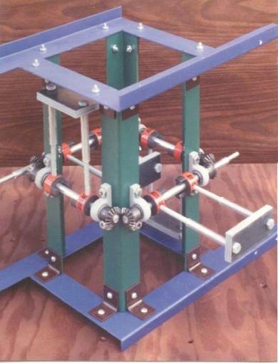
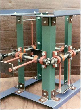
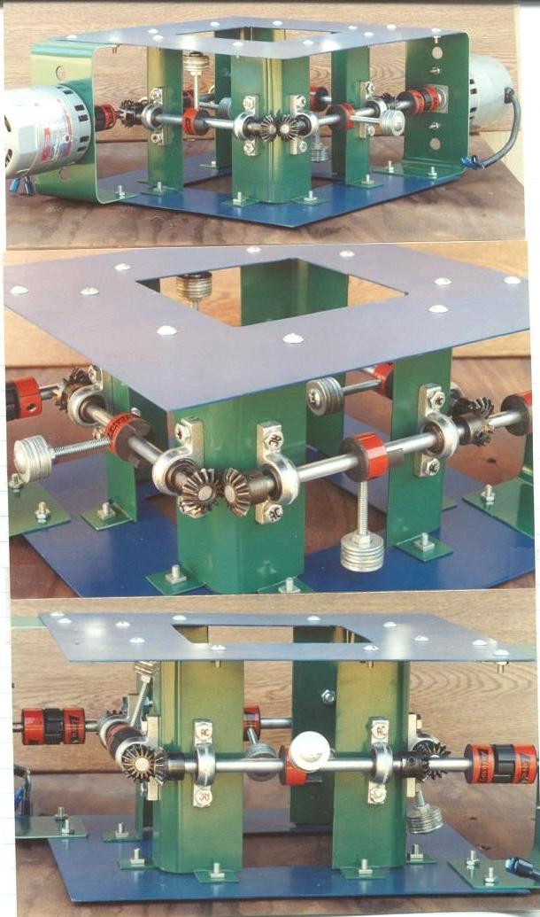
Click on each picture below to enlarge to full size. These picture depict the actual machine that was constructed. Fig 1- first build; Fig 2- stronger frame; Fig 3- Side view with additional weighting; Fig 4- Top, Side, and Front views; and Fig 5- Close-up of mechanism; Fig 6- combined views.
1.)
 2.)
2.)
 3.)
3.)
 4.)
4.)
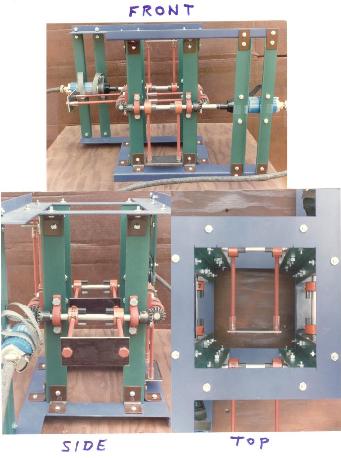
5.)
![]() 6.)
6.)
NOTE #1: In the drawing (Fig.1) the centers of mass (aka gravity) of loads 1 and 2 are each marked with a '+'. As shown, the center of mass for load #1 is at 'A'. The center of mass for #1 and #2 combined is exactly halfway between their 2 individual centers, at point 'B'. The center of mass for #3 and #4 combined is halfway between their 2 individual centers, at point 'C' (since load 3 is the same distance down (2R) that load 4 is up, 'C' is at the center of the frame with respect to all 3 coordinates). The center of mass for all 4 combined, is halfway between 'B' and 'C', at point 'D' and that Radius, from C to D, is labeled R. Since 'B' is the midpoint between #1 and #2 and is also always at the '2R' distance (the radius of each individual mass) from the center 'C', 'R' (the radius of ILCoM) is always 1/2 the radius of the individual weights. (because only 2 out of 4 are shifting in each direction - front to back or side to side)
NOTE #2: Example: If the total system weight, the 4 inertial loads included, is 10 times the sum of the weight of the 4 inertial loads, by themselves, then the ratio of the SCoM to ILCoM is 1:10 and the ratio of the SCoM to the radius of any one of the loads, weights, is 1:20. If the arm, rod, holding any one of the weights is about 3cm long, then the orbit of the center of mass is 1/10 of 1/2 of that or, about 0.15cm
GENERAL NOTES
The 4 weights are not the only loads on the system, the gears constitute an overhung load on the system and if the 4 weights revolve fast enough, and they may, the air resistance will become an overhung load also. However, the greatest problem is that, if the rpm of the weights is doubled, the radial load on the shafts is quadrupled (mass x radius x rpm x rpm x K = force).
If the mph of the 4 weights reaches or exceeds the speed of sound, a shock wave will be created (the sound barrier), which will quickly escalate and break apart the weights and their mountings and risk damage to anything and everything around it. In production, creating a partial vacuum will help eliminate this issue and reduce part of the load on the system. A minor issue: If the speed reached, matches the resonance of the shafts, the resulting vibration will tear everything apart.
- footnote: Tesla intended the world to have a free, wireless, source of power, as quoted, "My power generator will be of the simplest kind -- just a big mass of steel, copper and aluminum comprising a stationary and rotating part, peculiarly assembled," and further, "this device is...peculiarly assembled." By changing the orientation of the weights so that energy is produced without producing thrust (?), one might have the heart of the "wireless source of power" system that Tesla built but was unable to see commercialized???
Ending notes from Greg Smith. Greg is a programmer with a degree in Math and Physical Science (+ 2 years work on a 4 year Master of Theology degree) ...There were a couple inventions mentioned in the book, one in particular, where I could visualize the one drawing provided and it seemed simple enough that it could easily be built and either prove or disprove the books claims. I did build it and, though I did not get it "up to speed", the speed that we did achieve was enough that a friend, with some of the equipment that I needed to use, was even more impressed than I was that "Something is going on here". With lighter weights and higher speeds, the vibrations should have diminished but, they intensified.
In the process, I figured out the necessary speed required, not mentioned in the book, and that, became my stumbling block - inadequate motors to drive it. I then found Tesla's biography, Man Out Of Time, by Margaret Cheney, a thick, well received, book with lots of reliable information on the man. There I found how Tesla had contracted with both Allis Chalmers and with Westinghouse's railway and lighting division to build a 35,000 rpm turbine to "fly from New York to Colorado Springs in a contrivance which will resemble a gas stove" - July 7th 1912. If the turbine was to be a, relatively, lightweight power source to drive it, then that was what stopped Tesla (we may possibly be talking - again - about the use of the Bladeless Boundary Disk Turbine). The metals of his day stretched under the centrifugal forces and he got no further, publicly. Today, " The turbine is inexpensive and easily machined. " - SunWind Ltd. 3-12-79. In addition to weak metal alloys, Tesla had to contend with "negative reports" from engineers who did not understand his designs "claiming they would not build it as he wished...They said Tesla refused to supply enough information."
Maybe, again, they just could not understand something from Tesla "which had no theoretical precedent". Talking to an engineer, it took undue effort on my part to convince him that the center of gravity of the device, does travel in a circle. How could I explain that a force is generated "according to the right hand rule" (as opposed to the left hand rule for electricity)? How did Tesla know that? And, even if sliding the motor a little off-center, in different directions, could control speed and direction, how did Tesla know how much movement is needed? How did he "SEE" that in his mind, the way he seemed to see everything that he intended to build?
Definitions of a Motor are:
1. anything that produces or imparts motion.
2. an engine for propelling a vehicle
3. Elec.: a machine for converting electrical energy into mechanical energy.
Definitions of an Engine are:
1. any machine that uses energy to develop mechanical power - especially for transmitting motion to another machine.
An electrical coil sends electrons flying in a circle, in orbit about a center-point that is not the nucleus of the atom. The coil is sitting there, going nowhere, but its electrons are flying around in orbit and that paradox sets up a magnetic force-field. The coil is just sitting there; nothing is seen to be moving. But a voltage is applied and suddenly a magnetic force field appears and things do visibly start moving! Here we have a frame with some weights flying around in circles, going nowhere, just spinning, but it is "peculiarly assembled" and the net result is that the center of gravity of the entire device, still just sitting there, is in orbit - now we have the same paradox but the center of mass of the entire object is in orbit, not just the electrons.
Now, we have the potential for an atomic force field - the entire atoms are generating an orbital force field instead of just the electrons. Atoms being about 2,000 times more massive than their combined electrons, the force being generated here could be a few thousand times stronger. Because the protons are the charged particles doing the work, instead of the electrons, the force operates by the right-hand rule. However, even the 1/2 hp air motors were not powerful enough to handle the weight and the inertia of the "eccentrics". A more powerful motor is needed - and still keep the weight to a minimum The two air motors were great. They totaled only 24 oz. The massive air compressor was not part of the "system". Knowing that when it takes off, it will break loose from the air hoses and fall back down is no problem. Just proving that it works is enough to "turn heads" and start things rolling.
Next: Hydraulic motors? I am just experimenting. I don't know. I have been told by an engineer that slight imperfections in the balance and geometry of the system are nothing compared to the imbalances caused by the rotating weights. So that is a minor issue. Get "close enough" and we should be fine. From experience, I can tell you that the electric motors I used, started up so fast that 1 or more weights often came loose. The air motors gave more control - and so should hydraulics. END. Greg Smith's original site - http://www.pwsdb.com/Tesla-force-field-motor/Tesla-Flying-Stove-motor.php. Used by permission.
So, what we have are the following: It would seem that Tesla envisioned, and I'm sure built - three, perhaps four, distinctly different types of Flying Machines. One type was the cylindrical type (pictured in the artist's illustrations in Part One, which was powered either directly from the Ether, or from his Magnifying Transmitter. The Second type was again cylindrical in shape, and was probably powered by his bladeless disk turbine. The Third type is the one augmented on in this Part Two section, being mechanically derived, and controlled as if by the wheel-works of nature (taking the atom as its motive force, and re-creating it in a mechanical, oscillating form, as described above). The Fourth version was what we see in Tesla's patent regarding "Flying Machine Of Novel Principals" and is coined "the Fliver."
All I can say is we've got to build them all and see what happens!
Frank Germano, Global Energy Technologies.
![]()