Viktor
Schauberger:
the Austrian
& British Patents
Viktor
Schauberger
( 1885 - 1958 )
Click on the links below to jump to the individual patents
Viktor
Schauberger:
the Austrian
& British Patents
Viktor
Schauberger
( 1885 - 1958 )
Click on the links below to jump to the individual patents
Austrian
Patent # 117,749 "Jet Turbine"
British Patent#415,280 "Improvements to Water
Conduits"
Austrian Patent # 113,487: "Construction for Creating Wild Brooks &
Flow Regulation
Austrian Patent # 122,144: "Artificial Channel for Transporting
Logs"
Austrian Patent # 134,543: "Conduction of Water in Tubes &
Channels"
Austrian Patent # 136,214: "Installation & Correction of Flow in
Draining Channels..."
Austrian Patent # 138,296: "Water
Conduction"
Austrian Patent # 142,032: "Construction for Fabricating Tap
Water..."
Austrian Patent # 166,644: "Plow"
Austrian Patent # 196,680:
"Tubing for Flowing & Gaseous Media"
Austrian
Patent # 145,141
"Air Turbine"
Viktor
Schauberger
Viktor Schauberger's Patent collection
Austrian Patent #
117,749
( 10 May
1930)
Jet
Turbine
Viktor Schauberger
The object of the invention is a
hydro-electric device, which exploits the kinetic energy of a water jet for the
purposes of generating electricity.
The invention is characterised by a cone-shaped rotor, whose apex points towards the outlet opening, and rotates about an axis common to both rotor and water jet. The outer face of the cone is formed of upward-facing, concave, corkscrew-like blades. In this way the water-jet is split up and deflected from its path and imparts its full force to the rotor, so that, with the appropriate proportions between the height of the cone and the width of its base, and a suitable pitch of the blades, the size of which is dependent on the velocity of the impacting water-jet, the water flows from the machine quietly without creating spray.
An example of the arrangement of the invention is schematically depicted in the diagram.
 The rotor,
whose axle 1 is parallel and common to the axis of the jet exiting from the
jet-pipe 2, is formed of corkscrew-like blades 3. The ends 4 of the blades 3 are
curved upwards slightly towards the impacting water-jet so as to deflect the jet
and to effect the greatest possible transfer of its kinetic energy to the rotor.
In the jet-pipe 2 screw-like ribs 5 are incorporated, which, according to
observations, increase the velocity of the exiting water-jet and the efficiency
of the device.
The rotor,
whose axle 1 is parallel and common to the axis of the jet exiting from the
jet-pipe 2, is formed of corkscrew-like blades 3. The ends 4 of the blades 3 are
curved upwards slightly towards the impacting water-jet so as to deflect the jet
and to effect the greatest possible transfer of its kinetic energy to the rotor.
In the jet-pipe 2 screw-like ribs 5 are incorporated, which, according to
observations, increase the velocity of the exiting water-jet and the efficiency
of the device.
Claims:
1. The jet-turbine is
characterised by a cone-shaped rotor positioned in the axis of the water-jet, by
means of which the water-jet is split up. Corkscrew-like blades
(5) are
incorporated around the cone's periphery (7).
2. In accordance with Claim 1, the jetturbine is further characterised by a jetpipe (2) incorporating rifling ribs (5), which impart a spin to the rotor in the direction of its rotation.
PATENT SPECIFICATION (BRITAIN)
#415,280
Convention Date (Austria): Nov. 2,
1932.
Application Date (In United Kingdom): Oct. 31, 1933. No.
30,236/33.
Complete Accepted: Aug. 23, 1934.
COMPLETE SPECIFICATION.
Improvements in or relating to Water Conduits.
I, VIKTOR SCHAUBERGER, an Austrian citizen of I. Renngasse 6, Vienna, Austria, do hereby declare the nature of this invention, and in what manner the same is to be performed, to be particularly described and ascertained in and by,
The following statement:
This invention relates to means for improving the flow of water or the like in pipes, channels and other conduits, made of such materials as conduits are normally made of, for example, cast metal, sheet metal, wood, earthenware, and so forth.
It is already known to improve the flow of water in pipes and channels by providing them with guide-blades which project from the wall towards the centre, the faces of the blades being curved in such manner as to force the water from the wall towards the middle of the water-conduit, to which end the blades are in the form of a plurality of helices, similar to multiple thread rifling. Further it has been proposed heretofore to provide the faces of guide-blades with grooves running spirally in the direction of flow of the water.
The object of this invention is to provide an improved construction or arrangement of guide-blades whereby the forward motion of the water in the core zone is favored in comparison with the flow of water in the region of the walls. Simply stopping the flow of the wall zone would cause turbulence in the region between the core and wall zones, and the production of a sufficiently well formed core zone would be unfavorably influenced.
In the case of this invention however, the wall zone of the water is divided up into separate whirl formations which are of such a structure as to possess sufficient interior stability to have little tendency to break up, and therefore as a whole to produce a sheath of water favourable to the progress of the core water.
In accordance with the foregoing, according to the present invention, guide-blades are employed which are twisted in the manner of turnings in such manner that two co-operating guiding members having screw-like surfaces are formed, one of which separates the wall zone of the water current from the core zone whilst the subsequent guiding member in the direction of flow imparts a rotary motion to the separated wall zone of the water, whereby the wall zone of water is divided up into separate stable whirls. The invention is preferably applied to guide-blades which are disposed in the conduit along multiple spiral lines, producing a multiple rifling effect, so that the wall zone of the water progresses with a generally spiral motion.
In carrying the invention into practice the guide blades may be in the form of substantially rhomboidal strips, the diagonally opposite obtuse angled corners of which are bent up towards the same surface of the blade.
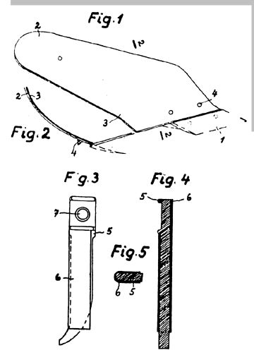
The invention is illustrated by way of example in the accompanying sheet of drawings in which Figure 1 is a plan view of a guide blade, and Figure 2 shows a pipe section with a guide blade therein, viewed against the direction of flow. Figure 3 shows the developed surface of a guide blade.
The guide blades are twisted in the manner of turnings, so that two guide members are formed, one at each end, as shown in Figure 1. These two guide members impart a spiral motion to the wall zone of water which flows generally in the spiral direction 3, thus producing a spiral sub-motion of the wall zone within its general spiral movement.
The guide blades 2 are preferably, as shown, disposed in the pipe 1 along multiple spiral lines 3, it being understood that, for the sake of clearness, one blade only is shown in the drawings. The guide member 4 of the blade 2 serves to impart a spiral flow directed away from the centre of the conduit, so that the wall zone becomes separated from the core zone of the water, whilst on leaving the part 5 of the blade, a spiral movement directed towards the middle of the conduit is imparted to the wall zone of the water stream The action of the strips 2 is improved by ribs 6 provided on the surfaces of the strips 2 as shown in the drawings, and the ribs may be thicker at the roots than at the tips so that the intermediate grooves narrow towards the surface proper of the strip 2.
Instead of being formed from a common strip 2, the guide members 4 and 5 may be made separately from each other. The guide blades may be made of metal, wood, clay, earthenware, or of any other suitable stiff material.
Having now particularly described, and ascertained the nature of my said invention and in what manner the same is to be performed, I declare that what I claim is: -
1. Water conduits having blade like elements projecting from the wall towards the central portion of the conduit, and providing guiding surfaces for the water, wherein the guide blades are twisted like turnings, so as to produce two co-operating blade like members having screw like guiding surfaces, one of the said members separating the wall zone of the water current from the core-zone, whilst the subsequent member in the direction of flow imparts a rotary motion to the separated wall zone of the water, whereby the wall zone of water is divided up into separate stable whirls.
2. Water conduit according to claim 1, wherein the guide blades are disposed in the conduit along multiple spiral lines, producing a multiple rifling effect, so that the wall zone of the water progresses with a general spiral motion.
3. Water conduit according to claim 1, in which the guide-blades are in the shape of substantially rhomboidal shaped strips, the diagonally opposite obtuse angled corners of which are bent up towards the same surface of the blade.
4. Guide members for use in water conduits, or water conduits provided with guide members constructed arranged and adapted to operate substantially as described and illustrated with reference to the accompanying drawings.
Dated this 31st day of October,
1932.
CHARLES S. PARSONS,
Chartered Patent Agent,
Thanet House, 231,
Strand, London, W.C. 2.
Redhill: Printed for His Majesty's Stationery Office, by Love & Malcomson, Ltd.-1934.
Austrian Patent # 113,487
(June 10, 1929)"Construction for Creating Wild Brooks & Flow Regulation"
by
Viktor SchaubergerThe invention corresponds to a construction for creating wild brooks and flow-regulation through the speed of water that is dammed, so that with oriented stones no destruction may come along the course of the waterpath through the damming constructs, and to place the central line of the watercourse in the middle of the stream.
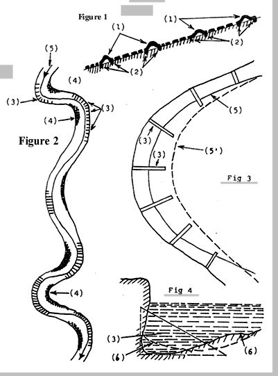
The invention is illustrated in the drawings; Figure 1 is an example of water-conduction and damming in the shape of transversely-placed dams.
The dams (1) are hollow and made of concrete placed and anchored to the ground with suitable anchors (2), so that they cannot be displaced by the streaming water. The striations are placed against the direction of the waterflow, upon which the water runs and along which it will sluice; through this coursing the water loses the greatest portion of its energy and does not strike too hard against the placed dams, forcing them out of place.
The dams can be placed at far or close distances from each other in the course of the constructed brook. In order to lay the theoretical middle of the stream in the midst of the flow in far-off places and also to prevent the destruction of the river shore through erosion, we will place constructions by the sides of the flow that will act as dams as seen in Figure 2. In this figure the dams are indicated by (3), while the stones are placed at (4) in opposite places. The middle line of the waterflow (5) runs through them as illustrated.
Figure 3 shows in greater detail one of such constructs and Figure 4 a transverse cut through one of them.
The constructions (3) are essentially triangular-shaped, and are jammed into the soil against the shore so as to elevate and make the water flow towards a middle point.
The effect made by these constructions is further illustrated in Figure 4, where the dashed line (6)-(6) in the transversal cut of the ground before the construction, which obliges the ground to place itself along the dashed line because of the disturbed waterflow.
The oriented stones are placed between the constructions (3) and this builds a zone of still water close to them, next to the shore, and also serves the purpose of directing the waterflow and to protect the shores from erosion through water (Figure 3). The full line (5) indicates the middle of the stream in the corresponding construction, while dashed line (5�) indicates the middle line in the brook under the influence of the constructs.
Figures 1-4
Austrian Patent # 122,144
(April 10, 1931)"Artificial Channel for Transporting Logs"
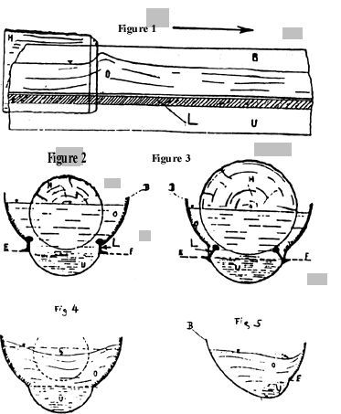
by Viktor SchaubergerThe transportation of logs and other varied loads through water channels and other artificial channels, though its low cost makes it competitive against other transportation means, suffers under the condition that when moving along the water flow some logs, especially in curves, tend to remain stuck and in this way sop the following logs, diminishing the general speed of the transport. This is especially true for hard and dense woods that remain at the bottom of the channel and move forward very badly.
It is known that the speed displayed by logs in water channels is greater than that of the waterspeed; at those places the speed of the logs greatly surpasses that of the transporting medium and it is seen from Figure 1 that the floating log creates a frontal wave (0) as it moves.
While lighter wood (Figure 2) floats witho0ut problems, heavier wood sits at the bottom of the channel (Figure 3) and remains stuck; therefore the water impulse in channels is not enough to produce the usual motion through sliding without external water spillage.
The invention pertains to a discovery that corrects these evils, namely the elimination of water spillage through the implanting of wedges made of wood and the transportation of hard and dense woods through sliding in the channels.
The speed of the water depends overall also on its sliding over the channel walls; in the usual slanted channels, this important factor is eliminated because of their construction.
The channels� cross-section is not semi-circular or straight, but rather, as seen in Figures 2, 3 and 4, semicircular (B) with an added semicircular bottom (U) which radius is half that of the upper portion (B), so that along the line (E)-(F) in Figures 2 and 3, a resting portion (L) can be included; the internal wall at the upper semicircular portion is of striated material (unretouched cement, directionally nailed wood, etc.), and the underlying portion (U) of a sliding material (flattened cement, polished wood, etc.), so that the water speed in the lower region (U) is much greater than in the upper part (B).
This causes at once the sinking of water in the middle of the stream (Figure 4); in practice, when a weight falls a certain distance, the water striking against the striated channel walls moves further, maintaining the mass (H) in the midst of the flowing medium by means of the polished underzone (U) that displaces the water faster.
When transporting floating light woods (Figure 2), this will not cause any disorder in the flow of water, for the underzone (U) will run faster than the upper zone (B); in this manner it will not be necessary to build dams outside the channel to contain the spilled water.
From light woods we expect little problem, but with hard and dense wood we must expect it to sink deeper and to advance with difficulty, so that this kind of wood will sink itself into the faster-running underzone (U), and advance in this fashion as if advanced by a transporting band.
When transporting hard and dense woods (Figure 3), different laws come into play; the wholly submerged log (H) is entirely in the faster-running water, so that the pressure upon (E) and (F) of the submerged sliding skids (L) makes them enter into action, for this time the usual impulse of water is not enough to make the log (H) advance. If these means are not added the logs must remain stuck in the bottom of the channel.
In opposition to the present (1931) transportation of hard wood through channels built with hardened materials, the dense and hard wood will be transported by doubly-concave channels with wall built with lighter materials, for they are not obliged to withstand such heavy loads. In curves, where the moving wood is obliged to follow them we can, through the proper construction (Figure 5) of the channel, with only a one-sided channel wall, make the log move towards the outside where it will be held by the running water along the curve; if need be, we can add sliding skids (L) as seen, which can be improved by the addition of wheels.
Figures 1-5
Austrian Patent # 134, 543
( August 25, 1933 )"Conduction of Water in Tubes & Channels"
by Viktor SchaubergerThis invention relates to the concentration of flowing water within polished conduits (pipes), channels and tubes, so as to increase the amount of flowing medium passing through them.
The inventor has discovered that when a certain kind of turbulence happens in flowing water, then a temperature difference takes place within it, producing also a difference in the water speed, and that this happens especially in Waltz-like flows.
It is known that to hinder sedimentation, water channels and tubes are built of circular cross-section, so that the flowing medium may drag with itself any sediments left; this is to provoke a screw-like movement of water so that it may attract all particles in its path.
This invention pertains to a further development of this principle, to drag sedimented masses with moving water.
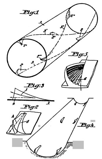
The main idea of this invention is seen in Figure 2, where the usual path of flowing water (4) is detoured by a wedge-shaped device into a different way (5).
Figure 5 shows an improvement of this idea by adding striations (6) to the wedge placed on the inner wall of a channel or tube.
In Figure 1, we see the wedges grouped (2)-(2�)-(2") in groupings of three, and producing as a result the screw-like flow (3)-(3�)-(3") through the internal portion of the conduit (1).
This makes the waterflow concentrate at the center of the tube, with a concentrical motion, dragging along any particles left upon the walls.
Figure 3 also shows, in a lateral view, how the normal water path (4) is changed to a concentrical one (5), to generate a concentrical flow in the flowing medium.
Figure 4 shows how open semi-circular channels can also be adapted to the same purpose.
Figures 1-5
Austrian Patent # 136,214
(January 10, 1934)"Installation & Correction of Flow in Draining Channels by a Contention & Stabilization of Dammed Water"
by Viktor SchaubergerThis invention pertains to an installation related to the conduction and regulation of flwo in water channels by contention and stabilization in higher levels by means of dams integrated into them that depend on the outer temperature of flowing water and mixing at will of light and hard water conducted out of the basin by its own means, with which it is convenient to direct the outer-flowing hard water for cooling the layers of lateral walls of the dam of the basin, as will be shown herein.
It is known that for the management of water channels in all channel-building techniques that a weighty argument, such as water temperature in earth vessels and air temperature as the temperature difference between still and running water, is always left out; and it is also known that the temperature differences between two or more watercourse modifies their speed when they mix.
So far, only through artificial constructs in dams, the naturally-built water channels running underground or only through ramparts (where only hard water with a temperature close to +4 degrees C. comes out), or by means of aquaducts placed atop dams (through which channels of only light water of high temperature flows), find obstacles in their coursing through the channel and cause erosion in their shores.
However, through a channel can also flow those waters with the corresponding right temperature, so that they can be directed to damming the water masses and to diminish their forward-going impulse or to increase their speed and their forward-going impulse in the willed direction. We can also affect works of shore-correction just by correct regulation of water temperature and also through the emplacement of dams which capacity of endurance is directly proportional to the amount of water dammed and also to achieve an obstacle-free flow of water. The widening of the channel through the emplacement of stones or elimination of same (ballast banks) and the elevation of the shore, especially in curves, can be made by the corresponding directing, but usually provokes a counterflow that erodes the whole work. Through several devices that will be explained here, it is possible to steer both light and hard waters, corresponding to the temperatures of each and also to the related fall of temperature, so that by means herein explained each water will run along its own level.
At the same time with the regulation of the waterflow, it is necessary to install in the construction of the closing dam of the basin, pipes that will effect the cooling of the dam�s pores through the sides of the dam by means of small watercourses directed through the materials.
Then as temperature diminishes, the water within the dam�s pres loses its attraction for dissolving salt and other stuffs, until it reaches its balance point at +4 degrees C, at which its capacity for dissolving is the least and the filtration in the dam�s wall is the strongest. So far, it is then when the light water infiltrated in the wall for cooling will go inside the materials through the pores; in this moment, the channel walls close to the dam are filled with hard water at a temperature of +4 degrees C, which lose their salts into the neighboring ground as they move, creating in a few weeks of impregnation a further barrier against erosion, and if frost comes, it will also contribute to the strengthening of the walls
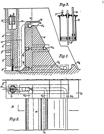
In the drawings we find a further explanation of a device for this kind of installation; it is seen in transverse cut in Figure 1 and in upper view in Figure 2; at Figure 3 we see an internal cutaway view of the apparatus for steering water.
For the sake of regulating the flow of cold hard water and warm light water, ground nozzles (O) are placed in the dam chamber (K) of basin (B) on both sides of the dam, which doors are activated through a floating device (G) that moves because of temperature differences. The pipes (W) of the nozzle (O) lead up to the upper-placed potion (K1) where the flow conduits (U1)-(U2)-(U3), which are closed through gravity-activated valves (V1)-(V2), branch in different heights from the upper-going pipe (W), and that lead further into the lateral wall of the basin, spreading out there into the corresponding casts. At the foot of the dam�s internal wall will be conveniently placed the outstanding portion (K2) to produce a whirling and better mixing of the water masses flowing over the wall. The door (T) in the nozzle (O) cleaves the soil of the water channel, sinking itself into it, and is connected vertically by means of a shaft (F), coursing inside the dam�s wall (H), with the floating device (G) that is built as a submersible bell. In the illustrated wall (H), we find at different heights over the ground-nozzle (O) tube-shaped outlets (A) that communicate with the tube leading upwards to the bell (G) and allow the automatic emptying of the water basin.
When the pipe (W) is allowed to fill through the opening of door (T), it will allow a communication between the pipe and the basin that will release pressure from door (T) unilaterally, and in this fashion allow its free motion upwards. The door (T) should be built of wood to allow the free motion of the bell (G) when the right water level is attained. The floating bell (G), which connecting shaft (F) goes downward, can in this fashion, and because of the only motion it is allowed to make, float upwards; the bell (G) in Figure 3 has an air valve (P) through which opening can be introduced pressurized air within, so that the door (T) will be activated at once. Through both an open end and with the outstanding tube (R), we can create a flow of water through the floating up or down of the bell.
When the diving bell is fully sunk, without any air margin, it acts to totally close the valve; and when we inject air within it, then raises to allow the opening of door (T).
In normal work, the atmosphere imprisoned within the bell (G) is equal to the usual atmospheric pressure and thus the outer temperature of the environment acts as a control; depending on the imprisoned air volume within (G), the outer temperature will make t raise or descend, allowing the steering of door (T) upwards, so that the mass of hard water that will be conducted through the nozzle (O), the pipe (W) and the flow tubes (U1)-(U2)-(U3), will depend on the changes of outer temperature; the light water flows over its own flowing plate placed atop the dam�s crown in the basin.
The interpenetration of light and hard waters can be improved through the construct (K2) placed at the foot of the dam�s inner wall, and also because of the fact that hard water falls vertically while light water does so spirally through flow tubes (U1)-(U2)-(U3), so that during their fall they will combine.
Through heating from the sun�s rays, the diving bell (G) will further raise the door (T), and through the channel a greater percentage of hard water will be eliminated with respect to the light water that flows over the dam�s top, and instead with cooler external temperatures the door (T) will remain either totally or almost totally closed and the channel will only conduct warm overflowing liquid.
For a better mixing of light and hard water flowing over the dam�s top, I have placed the flow tube (U2) in the lower part of the dam�s wall (K), so that it or (T) will prevent the water from overflowing the basin�s level.
The water flowing within the dam�s lateral walls contributes to further cooling them and also to leave deposited salts and other stuffs that it loses when reaching a temperature of +4 degrees C.
By opening the flow tube (U3) atop the dam�s wall, the upper portion of the dam can be affected as indicated in the former paragraph; the welfare of the dam�s wall (in all its portions) needs this process of impregnation so that its pores are closed and no filtration may happen.
The upper plate (M) serves to allow the overflowing of light water and to separate the hard water flowing through the conduit (U3), thus helping to further its endurance.
Figures 1-3
Austrian Patent # 138,296
(July 10, 1934)"Water Conduction"
by Viktor SchaubergerThis invention pertains to a further improvement of the tubes and channels shown in Austrian Patent # 134,543, where the water flowing within a conduit is led into the middle of the pipe to force it to effect a circular motion, as seen in the forementioned patent.
This invention pertains to an improvement of said idea by conveniently placing in the water�s path a device to produce whirling motions in the fluid.
The simple emplacement in the outer zone of the device will create turbulence between the center and the perimeter, so as to generate a well-defined flow zone in the center and layers of well-established stability from the perimeter inwards. The emplaced devices are of the kind illustrated in Figure 1, where we have an element (2) with its two ends bent (4)-(5) and striations dug out at the back (6); this device, when inside the tube (1) as seen in Figure 2, will meet the incoming flow and twist it along the new path (3), so as to createa circular motion in the liquid.
Figure 3 shows the device of Figure 1 straightened out so as to show its true shape.
Figures 1-3
Austrian Patent # 142,032
(June 11, 1935)"Construction for Fabricating Tap Water like that of Natural Springs"
by Viktor SchaubergerIt is known that, to fabricate mineral water through devices, without any unhygienic condition in the pipes or through the mixing of salts and compressed gases under pressure of at least 2-3 atmospheres, this is usually made under an even higher pressure.
It is also known that to generate soda water the water will be mechanically made to flow through carbonic acid under a pressure of 12 atmospheres, so that the corresponding enrichment in the forementioned cells make the water "active". In other procedures, this is done through "cracking".
The creation of artificial mineral water will also include carbonic acid under more or less great pressure of at least 1 atmosphere, so that the salts will mix evenly, as is done in several kinds of mineral water; and in other kinds of waters there is a slight dissolution of carbonates (for example, sodium bicarbonate) that also include carbonic acid, obtaining from this a prickling taste. In the forementioned procedures it is necessary, for producing a good mineral water, that the ingredients not be in free form but in combination and in relation so that the final product be as similar as possible to natural spring water.
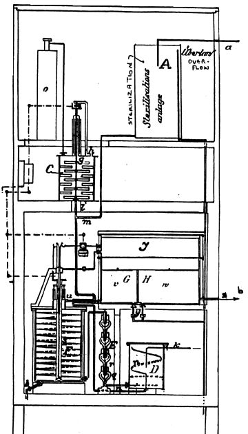
As shown in the Figure 1, sterilized water flows through cold mercury light in tube (M) and mixes with the diluted salts coming from (1). In container (C) the mentioned salts are diluted in water and well mixed by revolving fan (G). The mixture and kinds of salts direct themselves naturally through the sterile water outlet, and do so with different and permanent degrees of hardness.
On the other side, so that the concentration is not too high, the artificially generated mineral water�s hardness must not exceed factor 12 so that industry may not be hindered by it; anyway, outgoing water needs for every 10 liters output 1 liter of diluted salts in the following constituency and proportions:
Sodium Chloride (NaCl), 0.02 gr
Magnesium Sulphate (MgSO4), 0.02 gr
Sodium Biphosphate (NaPh2), 0.02 gr
Potassium Nitrate (KNO3), 0.008 gr
Calcium Oxide (CaO), 0.2 grThe kind and proportion of these salts are the results of several hundreds of experiments. While the calcium oxide dissolves itself in water, on the other hand the calcium hydrate is very sensitive to the oxygen in the carbonic acid, and thus is affected by it and the mercury light.
For the sake of regulating the liquid flowing out of the container (C), this is inside at a constant pressure of 0.1 atmosphere = 1 meter of acid water; the concentrated diluted salts will fall dropping along the pipe (1) and when mixed with the contents from (A) will flow into the apparatus (D) which turns them into droplets, where they will jump from the outflow holes of pipe (N) towards the walls of the apparatus (D); during the process the water already processed through carbonic acid will flow outside through the tube (K).
The droplets of both mixed liquids fall downwards and mix in the way as happens in nature, where the droplets of rain first lose their salts and diluted gases when hitting the ground. This mixed water flows within and through the tulip-glass device (E), where it always goes up in the outer tulip glasses and down in the inner ones, so that it will pass into the other following tulip-glass vessel after it has climbed into the innermost one of the former stage and thus continues its flow. The water makes a meandering motion to carry on the following indicated goal.
The gas, especially carbonic acid, collects itself in the upper portion of the tulips and will then, through the corresponding growing pressure, flow through pneumatic tube (R), in which fine nozzles is also injected water for flowing, so that the carbonic acid that is not already combined with the water will be later. On the axis of this device�s stages are placed alternately gold and silver foils, isolated form each other; between both metals there is an electric potential that creates a reduced ionization in the flowing liquid.
In its further motion, water penetrates into the main mixer (F), which is insulated against heat and silvered within, and within which is located an upwardly spiraling path which direction of winding goes against that of the snail and is made out of wire mesh.
On the spiral�s surface are orderly placed cooling spirals that take the temperature of water from 17 degrees C to 4 degrees C. The goal of this temperature fall is to properly combine the chemical elements. The absorption of the gases in water will be increased by the cooling, and otherwise makes possible the combination and enrichment of free carbonic acid of the resulting masses without the use of pressure.
The Ca(HCO3)2 presents a weak exterior combination that the enrichment with the forementioned carbonic acid had worked out, but the enrichment of Ca(HCO3)2 with carbonic acid is possible only through cooling in water and the maintenance of an even temperature.
The temperature of outflowing water must not be over 20 degrees C and its final temperature (once it was processed) should not be over 4 degrees C; it must also be taken into consideration that the speed of flow must not be too fast to allow the proper mixing of liquids; after leaving the container (F), the liquid is made to flow through gold and silver foils until it reaches vessel (I), which is divided into chambers (G) and (H).
First, the water that overflows from (G) falls into chamber (H), and so on out of the device (Z).
By the treatment of water as indicated, many reactions are produced; first of all, the water is made wholly drinkable. It is also necessary to eliminate any possible exposure to light during the process, for light falling on the treated liquids produces a loss of quality in the final results.
Figure 1
Austrian Patent #166,644
(August 25, 1950)"Plow"
by Viktor SchaubergerIt resulted from numerous experiments that a better plowing of the soil can be achieved with copper-covered plows instead of using plows made of iron or steel. This difference becomes stronger when one notices that the speed of plowing becomes faster and that the friction between the ground and the corresponding portion of the plow is greater.
This effect of greater speed produces the slow disintegration of the copper cover, and the minute copper particles deposited in the soil produces a catalytic effect that in turn generates better water retention in the ground and also a further increase in the quality of plowing.
These findings were made when passing a plow which body was either covered or entirely made of copper.
But as the building in whole of the plow with copper is disadvantageous, it will be convenient to cover those portions with copper layers in hardened condition, which can be made through several different methods. The deposit of copper particles under the ground does not break the magnetic permeability of the soil, as does iron or steel.
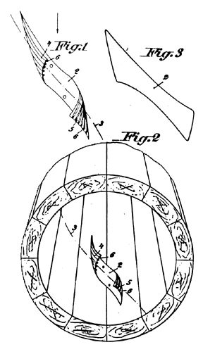
Two embodiments are shown in the illustrations. Figures 1 and 2 show a lateral view and Figures 3 and 5 show a transverse cut, a longitudinal cut, and one plowing protrusion.
In Figures 1 and 2 is illustrated a plow with point (1) made of steel as usual, but it can also be covered with the corresponding copper cover; this portion cuts through the ground, generating friction in the process; another is in the smaller portion (2), upon which upper portion there is usually a small heap of sol because of pressure when the plow moves forward. It will be furnished with an endtail (3), also made of copper, that will create a "screwing" motion in the soil by means of sunk "screw" (4) located at portion (2). In order to make the whole of this latter portion hard enough, it must be hammered during construction.
The plowing protrusion (5), corresponding to Figure 3 to 5, is made with a backward open sheet (6) of copper; to fasten upon the protrusion the usual arrow, we use lock (7) of protrusion (5) placed at a high location and which is furnished with the corresponding key; here it is also convenient to place the copper cover by hammering upon the protrusion.
Figures 1-5
Austrian Patent # 196,680
(March 25, 1958)"Tubing for Flowing & Gaseous Media"
by Viktor SchaubergerAlready there are many propositions for the conduction of fluid or gaseous media so as to eliminate losses in pressure or speed of motion. Thus it is to prevent the formation of air vesicles that it is suggested an increase in resistance to flow as in British Patent #409,528, wherein is described a tubing that has spirals engraved within and which area in transverse section will be limited by two segments of circle arcs.
From the British Patent #28,543 (1913) comes a tube which transverse section is egg-shaped, which is furnished with guiding means to prevent the formation of water whirls. In the US Patent #1,655,197, as in the Swiss Patent #126,637, are indicated either conical or cylindrical tubes for the sake of limiting the sedimentation where the tube serves as axis for the dragging of sediments; this is further explained in Austrian Patent #28,099 exhibiting indented piping.
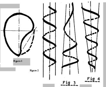
This invention pertains to a tube for flowing and gaseous media to prevent the formation of incrustations and to hinder the loss of flow speed, which cross-section is made out of several circle arcs, being the tube wound helically and having its cross-section an egg-shape with an indentation (Figure 1), and helically wound (Figures 2-4) around different forms.
With the aid of such tubing, the reduction in friction losses and the hindrance of incrustations within the pipe will follow; for the sake of increasing the former properties it is convenient to wrap the tubing and its cover around circular conduits. This axis of winding will also serve as axis for dragging along sedimentary materials, and will also contribute to reduce in scale the cross-section of the tube for winding.
Figure 1 shows the cross-section of the proposed tubing, and Figures 2-4 the different ways of winding the conduit.
In Figure 1 is shown the employed egg-shape with an indentation close to the (---) line; the winding of the conduit can be made as shown in Figures 2-4 around an imaginary solid or in the form of a circular spiral, or in any other convenient way.
In the winding or in its cover, in Figures 3 and 4, we can scale the shape of the winding to make it turn around those imaginary bodies or in a straight line. One can also arrange the tubing, in relation to the fluids conducted, to make the axis of winding equal to the one of dragging sedimentary materials to reduce incrustations and losses in flow speed.
Figures 1-4
Austrian Patent # 145,141
Air Turbine
(4-10-1936)
Viktor SchaubergerIt is known that impellers can be caused to rotate by moving air. It is equally known that an air current can be generated through evacuation. The present invention, however, makes use of mechanical and physical forces.
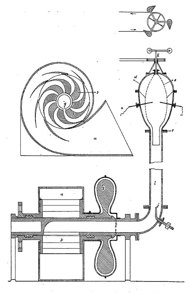
In the accompanying diagram (see fig. 19), the object of the invention is portrayed in Sections A-A and B-B. A snailshell-shaped housing a in which the impeller b is mounted is connected to a double-spiral pipe c by means of a hollow shaft d. The double-spiral pipe c is joined to an egg-shaped, hollow body e at f, which is divided into two spaces by means of a wire mesh g. In the inner chamber of e gas-burners or electric arc-throwers are incorporated that combust the inflowing gas at about 2,000�C (3,632�F). The inner chamber is connected to an exhauster via a heatable double-spiral pipe h. To this exhauster, streamlined, egg-shaped nozzles i are attached and the whole arrangement is activated by an external force.
The impeller incorporated inside the snailshell housing is constructed in such a way that fresh air can only enter the hollow shaft d when the impeller blade k passes over the slot j incorporated in the hollow shaft. The flywheel l, whose cross-sections are egg-shaped and which is mounted on the hollow shaft d, is installed in an externally airtight housing m. The air present in the hollow space n is sucked out through a connecting passage o, so that in the highly rarefied space n the flywheel is offered very little resistance to rotation. To maintain the combustion process, a combustible gas is introduced at p. The double-spiral pipe c mentioned at the beginning has been granted an Austrian patent, No. 138296. This pipe consists of an external pipe made of wooden staves and an asbestos sleeve. Within the latter there is a metal sleeve, which has wood-shaving-like metal elements bent out from the periphery, whose axis is inclined towards the pipe-axis at an angle of 30� to 45�. [3] [3: consult patent 138296] These metal elements are aligned along several spiral pathways. The peripheral air-masses will thus be forced to describe a path corresponding to a spiral within a spiral.
The inner metal sleeve is heated electrically. In addition, the heat arising from friction on the outer walls leads to the warming of the outer air-masses, through which in particular all the oxygen contained in the air expands, concentrates itself at the pipe-walls, becoming even warmer on its multi-spiral path along the pipe-walls. The remaining gases contained in the air pass down the centre of the pipe and rise through the agency of the gas introduced at p. Because the warmer and therefore more aggressive oxygen brushes along the outer pipe-walls and the colder residual components of the air flow through the inner region of the pipe, inner tensions arise between the materials due to the temperature differences obtaining, which become more pronounced the longer the distance travelled, until interactions ultimately occur. These interactions proceed in the form of small explosions and assist the reaction that takes place through the combustion of the highly energised gases within the egg-shaped safety mesh g.
In the egg-shaped body e a sieve (safety mesh) g is incorporated, outside of which the separated oxygen mentioned earlier accumulates, passes through the sieve into the centre, wherein, with the aid of the electric or gas arcs, it contributes to the almost complete combustion of the centrally conducted combustible gases. As a result a much greater vacuum evolves than has hitherto been achieved using currently known methods. At the same time the exhaust gases are reduced to a minimum and extracted mechanically via h and i. Through the creation of the vacuum in e, the air will be sucked in with even greater force, setting the impeller in motion in the process.
Claims
1. The air-turbine is characterised by the fact that the air-masses in a doublespiral pipe can be so strongly moved, that due to frictional heat and externally supplied heat between the peripheral air-masses and those streaming down the pipe-axis, differences in temperature arise, which lead to cold interactions in the air flowing through the double-spiral pipe, whose end-product is an almost total vacuum.
2. In accordance with Claim 1 the air-turbine is further characterised by the complete combustion that takes place in a partitioned chamber by means of a safety mesh having a pipe-shaped extension towards its base.
3. In accordance with Claims 1 & 2, the air-turbine is characterised by the fact that the attached flywheel is caused to rotate in a rarefied space.
4. In accordance with Claims 1-3, the air-turbine is characterised by the fact that the supply of air takes place pulsatingly through a slot in the hollow shaft.
5. In accordance with Claims 1-3, the air-turbine is characterised by the fact that the discharge of exhaust gases takes place by means of a heated pipe in which a temperature higher than that of the exhaust gases prevails.