The above writeup is on a few other sites aswell. This had happened some time in Jan this year. I'll try and post a few more videos using 12 Volts 1 amp 1.5 amp.... at the earliest and post the links. Try and save the vids incase theyre removed.
- Mon Aug 13, 2007 6:36 am ; Generation of H2 + O2 was 7CC per sec ; the H2 generation was 4.66 CC/sec and this works out to 16.776 lits of H2/hr
- Mon Aug 13, 2007 9:20 am Post subject: Hi again, Posted new video a while ago.
Its almost 1 amp and look at the way the leads to the WFC get heated up and burn the protective tubing. The tubing is in place so that the leads dont get shorted out. I have individual leads coming out of the WFC for each of the pipes.
http://www.youtube.com/watch?v=fiyfwWuA9gA
A closeup video of the burnt out leads. http://www.youtube.com/watch?v=nto66FTfdTg I have no clue as yet why this is happening. The setup probably needs more pipes I guess. I'll post info if I figure out something.
- Big-bubbles: The conditioning would take time...just keep lugging and you would end up with bubbles like the ones I get. The lights are pulse timing circuit visual indicators.
- Mon Aug 13, 2007 11:09 am : For Markin: I think the suface area for higher amps needs to be increased to get similar outputs as that of 0.5 Amps......so more number of pipe sets should inrease the efficiency at higher ameparages. Its a presumption but could be given a try in the future....any more ideas on increasing eff. at higher amps??
- Tue Aug 14, 2007 1:35 am : I would firstly advice you to go through all of stan's patents to have better understanding of the process.
There is a lot of important stuff in the US and International patents wherein in one of the patents he mentions higher efficiency of a tube setup compared to a plate setup for his proces (so I just didnt want to experiment with the plate setup on his process but I guess it works better with Bob's process). This answers your question Simon.
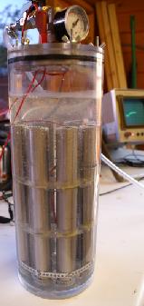
I could just give you everything but it could work for some and not work for some as the voltages and frequencies vary as per the WFC build and the impurities in tap water. I'm saying this coz till I made the changes when the components blew up on Dave's circuit i didnot get the right combo. The exposed surface area of my setup is much larger as compared to Dave's. He has 6 tubes of 5" lengths and mine is 9 tubes of 9" length so there had to be variations and the thickness of his pipes is different from mine...I have a gap of 1 mm between the pipes the outer tube thickness varies this gap. The gap used by stan meyer was 1.587mm (1/16").. As per stan the lesser the gap higher the efficiency.
Incase you are thinking of this gap youll have to use use three spacers of flexible foam on either end at 120 degree angles in the gap.I say fexible because you would not want any vibrations induced to be restricted as these vibrations help dissipate the bubbles from the surface. If you are not that well versed with mechanical skills, I would advice you to go for a higher gap as the space is very restricted and you might end up shorting the pipes. In longer lengths you should look for slight bends in the pipes as the pipes may get shorted. 1.5mm or 2mm gaps are also OK.
- Points to note: Check the new update of D14.pdf...theres an inductor added inbetween...its a must.
Patents show a variable resistor on the -ve side in between the WFC and the freq generator which everyone seems to have missed out (incl dave) in the '996 patent. This I had asked Dave about and he said it restricts the current going to the WFC.
My setup compared to Dave's has individual connections going to each of the 18 pipes.
Conditioning of the tubes takes a long time....SeaMonkey's explanatin stands good. Once you stop forming the brown muck you know you've conditioned the pipes and the gas generation increases at this point.
Kumaran I had subtracted 100% Faraday efficiency from the total and what you get then is the OU %. Your figure is for total efficiency of the WFC.
- Tue Aug 14, 2007 1:39 am ; You could always build Dave's setup without making any changes including the pipe thickness, height and diameters and achieve the same results as Dave did. His circuit should work for his WFC build size. Conditioning is the key to his generation.
- Tue Aug 14, 2007 2:49 am ; DONOT USE 316L AS LEAD WIRE THEY HAVE TOO HIGH A SPECIFIC RESISTANCE TO BE USED AS LEADS ; approxmately 46.8 times that of copper...incase you want to introduce a resistance you could always used a wire wound variable resistance.
This seems to have been the problem of leads heating up. Specific Resistances: Copper : 1.63 MICROHM-cm ; 316 : 75 MICROHM-cm
- Tue Aug 14, 2007 7:33 am ; I'm realy sorry about the patent number. its 4,798,661 and the variable resistance I was talking about is in Figure 1 with numbers 60a...to....60n on the inner tube.
I dont use a blocking diode. No there is no dramatic increase when you vary upuntil you condition the tubes. When I initially started off I could hardly see any bubbles emerging. But as the conditioning proceeds over a period of time you see the gas generation gradually increase. At a point where i was generating a lot of small bubbles I thought I reached the peak but I just wanted to see what would happen if I condition a little more and what I ended up with was making these large 10mm sized bubbles. Its not that the small bubbles accumulate to a bigger bubble but the moment the gen is switched on the large bubbles come rushing out, you can see this in the vids. I wonder if I condition some more I might endup with large bubbles only. Lets see how it goes.
The key to the whole process in my point of view is conditioning and this should go on for a while even after you stop making the brown muck and you end up with large bubbles like mine. It will take time but at the end of the day its worth it!
The dramatic gas increase happens in the range of 0.1 to 0.2 Amps in my WFC but above that you just need to keep checking as to where you get the highest efficiency for that particular WFC and it would be less than an Amp in any case. Look at my outputs the efficiency decreases as you increase the ampearage to the freq generator.
- Tue Aug 14, 2007 9:46 am Post subject: CONDITIONING OF TUBES!!!!! Alright guys make a note of this and save it some place
The conditioning process below was given to me by Dave Lawton and its what I followed religiously for months to reach the outputs. Consider this as the holy grail like I did and still do...
1. Donot use any resistance on the negative side when conditioning the pipes.
2. Start at 0.5 Amps on freq gen and switch off after 25 mins for 30 mins
3. Goto 1.0 Amps for 20 min and stop for 30 min
4. Goto 1.5 Amps for 15 min and stop for 20 min
5. Goto 2.0 Amps for 10 min and stop for 20 min
6. Goto 2.5 Amps for 5 min and stop for 15 min
7. Goto 3.0 Amps for 120 to 150 secs. need to check if WFC getting hot...if it does you need to reduce the time.
AFTER THE 7 STEPS ABOVE LET THE WFC STAND FOR ATLEAST AN HOUR BEFORE YOU START ALL OVER AGAIN. I used tap water for conditioning and no vinegar or any additives.... I donot know if adding something might work or not.
You would hardly see any gas generation at the beginning but it makes a lot of brown muck.....change the water after every cycle initially. DONOT touch the tubes with bare hands if the tube ends need to be cleaned of muck use a brush but donot touch!! As per my experience the brown muck if left in water for the next cycle heats up the water and you need to avoid this.
Then you see the reduction in generation of the brown stuff over a period of time and at a point the pipes dont make any brown stuff atall. You would have had very good generation of gas by now. You get a whitish powdery coat on the surfaces. Never touch the pipes with bare hands once this comes on.
DO THE CONDITIONING IN A WELL VENTILATED AREA OR PREFERRABLY CLOSE THE TOP AND VENT THE GAS OUT IN THE OPEN.
AS THE WFC IS LEFT ON FOR QUITE SOMETIME EVEN SMALL AMOUNT OF GENERATION CAN GET ACCUMULATED IN A CONSTRICTED SPACE AND COULD BE A HAZARD.
The above process to be done after annealing the pipes....see to it that no oxide formation is left on the pipes...use a detergent to wash off the pipes and rinse them thoroughly with fresh water.....assemble the setup including the leads and base.....finally flush the pipes with lots of fresh water......donot touch the pipes with bare hands after this.......
Good Luck and happy conditioning......RAVI
- Ravzz, Posted: Wed Aug 15, 2007 8:18 am:
I know about the passivation of stainless steels. Like I said before I dont know if it would work for this process.......even if it does I dont know if you could get the same efficiencies.
Its a short time process so you need to passivate the pipes once they are assembled so that you dont disturb the layer formed which is usually less than a micron thick. If this doesnt work you could always revert back to the regular conditioning process but you will have to disassemble the whole setup and sand paper the outside of the inner tube and the inside of the outer tube to get rid of the passivated surface and expose a fresh surface then reassemble and start.
Let me know if this works. PLEASE NOTE THAT POLISHED TUBES ARE NOT TO BE USED IN MAKING THE WFC
If they are the only ones you can find make sure they are not Nickel plated or Hard Chrome plated pipes and if they are Plain SS 304L or 316L but polished you could always use a sand paper.
You can use most of the 300 series Nickel-Chromium Steels but 316L would be the most preferrable and next would be 304L.......never go for 310 as this has the highest resistivity among the 300 series. Avoid Inconel grade pipes aswell.
Use ONLY SEAMLESS PIPES and not seam welded.
- Ravzz, Posted: Thu Aug 16, 2007 2:02 am :
I remember watching on one of Stan Meyer Videos where they mention the Output to be over 1700% faradays....I guess there's more work needed to be done in this direction.
Dave's unit was 250% OU mine looks a little higher....one of the reasons I think is because my unit is comparitively bigger 9" length 9 tubes compared to Dave's 5" length 6 tubes. Stans was 18"length 9 tubes...double the size of my WFC.
Is there a possibility that some thing like the Joe's Cell aether stuff is happening here?? Even Joe's cell takes a long time to condition and even that produces brown muck and doesnt do so after a while.....both have concentric tubes.. Needs very low amps...there are similarities....
Is there a possibility that the extra work is being done by Aether? Is joe's cell conditioning similar to the one mentioned above??
- Ravzz, Posted: Thu Aug 16, 2007 3:53 am:
There is another difference that needs to be noted compared to Dave's Replication. I didnt remember the exact gap between the pipes till patrick just asked me what were the differences between my setup....sat down and calculated....
The gap in between the pipes was: Outer Pipe OD : 25.317 mm ; Thickness : 14 SWG or 2.032 mm ; Outer Pipe ID : 25.317 - (2.032 x2) = 21.253mm
Inner Pipe OD : 19.930 mm ; Thickness : 14 SWG or 2.032 mm ; Gap is 1.323mm ( 21.253 - 19.930 )
and this adjusted to both the sides as the inside pipe is centered is 1.323/2 = 0.6615 mm on either sides of the inner tube.
So effectively the gap between the pipes is less than 0.670 mm. I went for a lesser gap by increasing the thickness of the outer tube.
If you go through Stans Canadian Patent he mentions that the lesser the gap between the pipes more the efficiency
I had a lot of difficulty in the alignment of pipe as they were shorting. Had to get them straightened on pipe alignment machine. Wouldnt advice people without engineering skills to go for this small a gap.
The higher output of my setup could be due to the smaller gap aswell.
- Ravzz, Posted: Fri Aug 17, 2007 2:44 am:
I,ve posted the video of the changes of the leads im doing right now. http://www.youtube.com/watch?v=BqSyTiPu8VI
- Ravzz, Posted: Fri Aug 17, 2007 7:04 am:
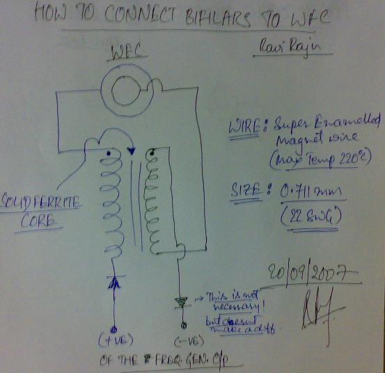
I havent spoken to Dave about the variations concerning the inductors....as for me I've made it on a Ferrite rod of 25 mm length 100 turns of Double Enamelled Electrolytic Copper (99.99%) of 22 SWG (0.711mm dia) which was what Dave suggested.
You could try the above till you are successful to an extent and then start experimenting with the variations and let everyone know if youre getting better outputs.
- Ravzz, Posted: Sat Aug 18, 2007 9:06 am:
Which tubes have you ordered? 316 or 316L.....the L stands for low carbon ... which supposedly works better ..... this is the surgical grade SS they use for implants.
O rings are a definite no no!! you will end up trapping some of the gas within the tubes if you restrict the outflow....effectively this would end up reducing the exposed tube surfaces to water in between the pipes and when you cut slots youre again reducing the surface area !! small flexible foam cut to a length of 5 to 6 mm and a width of 3mm.....insert the length inside the tube so the 3mm width is what you see from the top...this way you can increase the gap for the gases to leave the pipe end. Insert three foam pieces at 120 degree angles on both ends.
- Ravzz, Posted: Mon Aug 20, 2007 1:19 am:
... I had my tubes annealed to get rid the crystal lattice imperfections due to cold work.....and any traces of magnetism. They have to be in bright finish only you dont want oxidesof nickel / chromium or iron on the surface.
... You need to get the tubes annealed once they are cut and finished to lengths before being assembled. Its done in a separate inert atmosphere furnace of N2 or Argon. You have people who do heat treatment for metals .... they'll give you the procedure if you tell them the grade you're using.
- Ravzz, Posted: Wed Aug 22, 2007 3:12 am:
There seems to be someone else who's replicated Dave's setup.... I saved the video from youtube or google recently......I dont remember who this was or where I found the video but he seems to be tuning the Freq Gen with an AM radio sound. Please do let me know if you find the original poster of this video....converted and saved the video and finally got time to watch it last night.
His method seems to work!! and he's connected it to his car aswell.....he claims to have gotten an increase from 28 miles/gal to 45 miles/gal!! Thats an increase of 17 miles to a gallon!!
Check the video on how he tunes his WFC and his claims. http://www.youtube.com/watch?v=9fFp3CJZMTw
... You were asking me about the resistance on the inside tube sometime ago......as per stans Patent each inside tube is connected to an individual variable resistance.....you cant make those connections with two leads coming out of the WFC. I have 18 leads ( 9 +ve and 9 -ve) coming out of the WFC. This way you can do all sorts of variations you need without opening the WFC.
The transformer thing you're talking about are diode heat sinks of previous WFC trials and experiments....but the diode setup is defunct ....im using the connectors at the bottom of that setup which connects to the WFC there.....most of them are all old wirings from previous trials....I was trying a lot of combinations and almost all of them failed except the one recently posted....its all a mess up there.....Dont look too much into it hydro....its as simple as it was in the updated D14.....conditioning is what helped me get higher efficiencies and now check the link on top as to how this guy tunes it and he talks about the white powdery coat he has!!.....this comes only after conditioning!!
- Ravzz, Posted: Wed Aug 22, 2007 6:39 am:
I should thank Aaron for posting the video on conditioning of tubes.... http://www.youtube.com/watch?v=qXRMVZWrgSk
I had followed his postings and videos for a long time now....actually he's been one of the inspiring factors for me to build my system....thanks again Aaron.
He goes by the names Aaron Murakami / a1c3m / Qiman13 on the net. He has his forum postings on the WFC: http://www.energeticforum.com/renewable-energy
If youre looking for the exact technical language and the process...he's the man!!
- Ravzz, Posted: Wed Aug 22, 2007 8:46 am ; Post subject: Important conditioning info :
Another thing I remembered after watching Aaron's conditioning video was, when the power is switched on you see bubble formation on the external surfaces of the outer tubes just like in the video ..... this happens all along during the conditioning process.
I remember Dave saying that you know the tubes are conditioned when these bubbles stop forming on the external tube surfaces and you see a white powdery coat on the tubes.
I went on conditioning even after that and ended up with larger bubbles.
- Ravzz, Reply #112 on: August 30, 2007, 12:48:11 PM :
You could use the inner tube as a neutral electrode...by not connecting it with anything at all and connect the inner rod to the negative and the outer most pipe to the positive. From what i've read and seen neutral electrodes work...Joe's cell is a prime example of this.
Has anyone seen someone using neutral electrodes with voltage potential? well I havent.... looks like you have a new idea Kevin.... Definitely worth a try.
... Well youre almost spot on! The resistance wire restricts the current draw into the WFC. Try it before the inductor and after the inductor...see which gives the highest output. You dont need the resistance wire during the conditioning of the tubes its only for reducing the current draw.
Even I didnt know what this was for.....Dave told me that it would reduce the current draw when used.
Tell them that you need a bright anneal in nitrogen or argon atmosphere. Annealing is done after every cold work operation and at the finishing stage to reset the lattice structure. As we are cutting the pipes and slightly finishing the surfaces with sand paper to remove any imbedded impurities during tube drawing.... its all cold working .... so you need to relieve these induces stresses in the lattice through annealing. I'm a metallurgist Hydro so you can stay assured about this. Its normal manufacturing procedure.
- Ravzz, Posted: Thu Aug 23, 2007 12:21 am:
Let me mention this again: The best grade of SS to use is 316L ; Next preference is 316,304L and 304.
L stands for Low Carbon in the SS alloy.
316L composition: %
- Carbon : 0.03
- Manganese: 2.0
- Phosphorous : <0.45
- Sulphur : 0.03 max
- Silicon : 1.0
- Chromium : 16 to 18
- Nickel : 12 to 14
- Molybdenum : 2.0 to 3.0
316 SS nickel range is 10 to 14% and carbon being 0.08%
304 SS has lesser % of Nickel and Chromium and doesn't have Molybdenum at all. so judge for yourself which grade you would want to use.
- Ravzz, Posted: Thu Aug 23, 2007 5:34 am :
If you had told them to anneal in inert / nitrogen / Argon atmosphere it would be a bright finish.
Well if bright finish wasn't a criteria you could just use a gas torch to heat it up till red hot and let it cool off slowly...but you would end up with a blackish bluish discoloration. This is due to the oxide layer formation on the surfaces. I dont know if oxidised pipes work better but they do have high corrosion resistance. For all we know you might end up getting better outputs than any of us or the other way round but definitely worth a try.
If it doesnt work that well you could disassemble the pipes and use sand paper to remove the oxidised layers. They are usually a few microns thick.
- Ravzz, Posted: Fri Aug 24, 2007 1:07 am :
... Every metal or alloy when cold formed or cold worked has to go through a heat treatment process to relieve the internal stresses. Its finished and supplied in annealed form. I have my own industry and we work on stainless steels, inconels, cupronickels, ....... and precious metals like gold aswell for the semiconductor industry and we need to anneal not just at the finishing stage but in the intermediate stages as well for further cold work. Annealing is a compulsory procedure in every metal working process unless you require high temper and uneven stresses within the work piece.
By the way High Carbon Steels go through another heat treatment process called patenting .... these are high tensile strength steels and widely used in spring making.
Please stay assured that we do anneal Stainless Steels at our plant. If you didnt know even the copper wires you use everywhere are annealed....this is done on the wire drawing machines itself.
- Ravzz, Posted: Fri Aug 24, 2007 3:12 am:
I've switched on and switched off the Freq. Generated twice in the second video. To clear up any doubts some might have that there could be a another source than the freq gen input.
- Ravzz, Posted: Fri Aug 24, 2007 5:45 am:
... The higher output is all to do with the inductors in the D14 circuit and conditioning mainly and slightly through the resistance wire to reduce the current draw. Even without the resistance you can get the same output but another 0.3 to 0.6 amps extra but I feel this could be offset by making a bigger inductor. Just go on conditioning and keep reducing the Amp draw to the WFC gradually and the generation would kind of remain the same even at very low Amps. Once you condition the tubes your generation will dramatically increase and the current required will fall by leaps....this took me almost 3 months approximately to reach these outputs.
- Ravzz, Posted: Sat Aug 25, 2007 7:53 am:
I use the 555....never checked if it was heating up!
- Ravzz, Posted: Sat Aug 25, 2007 5:21 am :
... Hydro, if you are going for a bigger setup than Dave's. Then, change the 100 ohm 0.25 watt resistors to 0.5 / 1.0 watt resistors depending on the increase in exposed surface area. I use 1 watt.
- Ravzz, Reply #115 on: August 30, 2007, 12:59:19 PM :
Alright people there's something really weird happening in the WFC. Dave had mentioned some time ago that there's some glow in the dark.
I just checked it in pitch dark..... theres some kind of orange glow coming from the bottom of the WFC but cant make out exactly from where... tried taking pics but didnt work they got all pixulated. Any idea what this could be??
- Ravzz, Posted: Mon Aug 27, 2007 1:02 am:
I have no idea what it was. It was an orangish glow and comes intermittently for two or three secs then goes off for a while, you cant see any glow on top of the tubes but only at the bottom .... cant be the leads as theyre enclosed in plastic piping and the point where the wires are spot welded is also covered with silicone sealant....you can see this in the pics I posted. Could be Radiant Ener but thats what was happening....this couldve been happening all along but I never noticed it as I was always concentrating on the generation at the top of the tubes.
... Being a Mechanical Engineer I dont know too much about electronics. i got my circuit made by somebody and when ever there were problems I got them rectified by the same person and kept track of what changes he made and I've told you what the changes were.
- Ravzz, Posted: Mon Aug 27, 2007 1:08 am:
Check this post for the same thread in overunity.com ....this could be of help!! Im pasting it here for reference:
Ravi, Do you know the approximate frequency at which you are applying the square wave pulses to your WFC? The reason why is related to some research I did with a well known 'water as a fuel' research group.....
Here was the crux of my interesting finding: The findings are based on this youtube video from Dave Lawton: http://www.youtube.com/watch?v=miwbvsya3Ek , WATCH IT!
[4/1/2007 3:40:25 PM] Tao says: Just doing a simple calculation a tube in plain fresh water, the equation from http://en.wikipedia.org/wiki/Acoustic_resonance shows f=(n*v)/(2*L) where n corresponds to the harmonic, v is the speed of sound in the water, and L is the length of the tube....
So, lets simplify this equation, n can be always 1, v is 1435 m/s in fresh water according to Wikipedia.
So, f = (1*1435)/(2*L) = 717.5 / L = f , Just for fun, lets take the frequency Dave was producing Hydroxy at in his latest video on Youtube: 3425.781Hz
So, 3425.781 = 717.5 / L , L = 717.5 / 3425.781 = 0.21 meters , So that would be 8.27 inches long.... So, how long in inches are Dave's tubes? Just curious........
[4/2/2007 11:26:20 PM] Tao says: So, I asked how long Dave's tubes were, well, I looked up how long they were from an old post Dave did on the original forum back in 2004...
[4/2/2007 11:26:44 PM] Tao says: Dave said that his tubes were about 12.5-13cm (which is about 5 inches long)
[4/2/2007 11:27:39 PM] Tao says: so, calculating that into the equation: 717.5 / L = f , we have 717.5 / 0.1275 = f , so f = about 5650Hz
[4/2/2007 11:28:21 PM] Tao says: So, based on what it says at the END of that video on youtube, it says that the hydroxy was being produced at 3425.78Hz
[4/2/2007 11:29:00 PM] Tao says: BUT, they acoustic frequency came out to be 5650Hz, so I said, 'oh, too bad' seems there isn't much of a connection, I guess I need to do more research'
[4/2/2007 11:29:10 PM] Tao says: UNTIL, I just watched that video again..........
[4/2/2007 11:29:50 PM] Tao says: Look at what Dave was pulsing his DC at in the video: 5714Hz!!!! At 1:11 in the video you can see what he was pulsing at.......
[4/2/2007 11:30:58 PM] Tao says: Based on the equation for acoustic resonance, Dave was pulsing his tubes at the EXACT frequency at which those tubes will resonate ACOUSTICALLY in FRESH WATER...
So, my finding was basically this: Dave found the BEST gas production at the VERY SAME frequency that just so happens to be where his tubes resonate ACOUSTICALLY IN WATER ... HMMM...
Maybe it is nothing at all but a coincidence, but maybe there is just something to it........................
- Gheller, Reply #116 on: August 30, 2007, 01:33:54 PM :
... I edited the HTML and combined all Ravi's OUpower posts into one html file. http://www.overunity.com/index.php?action=dlattach;topic=3079.0;attach=12353 ravi-oupower-posts.zip , 94.95 KB
- Reply #117 on: August 30, 2007, 01:56:24 PM :
Thanks for your efforts in compiling the information Gheller, I took the liberty of copying it all to my website http://hh0.no-ip.info/ , it can be found just below the videos, I figured if it's on a webpage of it's own then it will not get pushed by other postings.
- Reply #121 on: August 30, 2007, 03:10:45 PM :
I ripped all the posts from the old icubenetwork because I was there when Dave made his WFC, and there when qiman13 and I started the offshoot 'radianth2o' yahoo group... I will post those icubenetwork files soon enough...
For now, here is the entire overunity.com Ravi thread in a zip file, all manually edited html files, enjoy. 'ravi-overunity-posts.zip' , 2074.78 KB http://www.overunity.com/index.php?action=dlattach;topic=3079.0;attach=12354
- Reply #124 on: August 30, 2007, 03:24:22 PM:
Below are all the PDFs I hand-made in 2005. Each PDF is a complete recreation of a different thread that was at ICUBENETWORK when it was active. The PDF's titles are the same as the titles that each of their respective threads had at icubenetwork.
It was the origin of Dave Lawton's release of his replication of Meyer's system. It was also the origin for the radianth2o yahoo group and qiman13 ( http://youtube.com/qiman13 ) who has also been releasing videos just recently along with Ravi's.............. Have a good read guys, this is the GENESIS material to all these Meyer replications!
- Daves_Cell.pdf, 399.83 KB ; http://www.overunity.com/index.php?action=dlattach;topic=3079.0;attach=12355
- Daves_WFC_Setup.pdf, 83.19 KB http://www.overunity.com/index.php?action=dlattach;topic=3079.0;attach=12356
- Stanley_Meyer_Theories_and_Circuits.pdf, 496.09 KB, http://www.overunity.com/index.php?action=dlattach;topic=3079.0;attach=12357
- Secrets_of_the_Water_Cell_Explained.pdf, 508.58 KB, http://www.overunity.com/index.php?action=dlattach;topic=3079.0;attach=12358
- Bedini_SG_-_THE_Key_to_Meyers_circuit.pdf, 517.95 KB, http://www.overunity.com/index.php?action=dlattach;topic=3079.0;attach=12359
- Reply #178 on: September 04, 2007, 10:40:35 PM :
Here is the high res picture of Dave's actual setup with his light bulb being powered by the Electron Extraction Circuit... The EEC works folks, believe that... One more vindicating action that supports Meyer...........
See picture 'radiant2.JPG', 313.73 KB, 1663x1210 http://www.overunity.com/index.php?action=dlattach;topic=3079.0;attach=12464
PS - I was just looking up similar 83,000uF 50V caps to see what they could look like, and they look very similar to the one in Dave's pic there...
- Reply #183 on: September 05, 2007, 03:14:48 AM :
Guys another [lawton-Ravi] replication was sent to me. Plus a guy on Hydroxy just posted he has one too.
Quote on the attached: "Paul estimates that he is getting the same output as Dave. He intends to improve substantially on that, but he has to fix a leak in the base of the cell before he continues development. His web site is "
Hydroxy post: "I am using a meyer cell with a Dave Lawton circuit. I increased my gas milage in my ford escort to 45 MPG from 28 MPG. The Lawton circuit fryed my alternator. My solution was a $20 dollar boat battery charger that plugs into a car cigarette lighter. I use that to power my Lawton circuit now.
Yahoo! Groups Links: To visit your group on the web, go to: http://groups.yahoo.com/group/Hydroxy/ "
- PGreen2.JPG (1460.26 KB, 3008x2000 - viewed 408 times.) http://www.overunity.com/index.php?action=dlattach;topic=3079.0;attach=12469
- PGreen1.JPG (1887.95 KB, 2000x3008 - viewed 28 times.) http://www.overunity.com/index.php?action=dlattach;topic=3079.0;attach=12470
- Reply #184 on: September 05, 2007, 03:26:24 AM :
Guys, as you may know Dave has reported Cold current electricity from the cell, Patrick just sent me this, im not sure if he has uploaded the new 'cold current' circuit to the cell, but rest assured the plans wil be in there
"I'm afraid that papers of that nature just leave me cold (no pun intended) as I gain nothing from them. I don't think in mathematical structures.
The subject of radiant, or "cold" energy is not well defined at this time. Our familiar conventional electricity appears to be a transverse oscillation while the "cold" component appears to be a longitudinal oscillation. Consequently, none of our instruments react to cold electricity and while it can power lights, motors, heaters, etc., the only way to actually measure it appears to be to charge a lead-acid battery using it and then measure the power stored in the battery by discharging it. John Bedini remarks that after forty years of searching, that is the only mechanism which he has found.
Electromagnetic pulsing appears to be the main way of accessing this energy. Bob Boyce's electrolyzer gets 10 x Faraday's supposed maximum, through magnetic pulsing of a hundred stainless steel plates in a row. This is effectively pulsing a hundred capacitors in series as the electrolyte is essentially a dielectric. Bob gets a major power gain by pulsing windings on a toroid, which is definitely a significant shape for cold electricity. The power gain can be 10,000 amps of hot electricity, and as that is effectively the "losses" where cold electricity is concerned, the real "cold" power is so much greater that it can trigger a ground feeder leading to a lightning strike. Bob found that out the hard way and was very lucky to survive being hit by that lightning strike.
The toroid is at the heart of many different COP>1 devices and its effect can be simulated by generating a rotating magnetic field without a toroid (devices like the Adams Motor for example). That of course, is not the whole picture, as Thomas Henry Moray achieved massive power input without anything like that, so how do you explain input from an aerial as that appears fairly passive?
So, the bottom line is, that while I know that cold electricity can be tapped with rotating magnetic fields, strong dipoles (including sharp DC pulses and permanent magnets) and passive devices like aerials, Coler devices and the Joe Cell, it is clear that I really don't understand anything significant about it.
- Reply #187 on: September 05, 2007, 06:11:47 AM :
'bigfatpothead' on youtube running his car on Dave's setup and his mileage gain was around 17 miles/gallon which works out to 62% increase in mileage!! (by far better than any available off the shelf).....the video is ( http://www.youtube.com/watch?v=9fFp3CJZMTw ).....this system was the same size as Dave's , wouldn't be surprised if the mileage gain is over 120% as my unit is much bigger
- Tao, Reply #194 on: September 05, 2007, 02:20:49 PM:
Meyer's EEC circuit layouts compared to Lawton's recently posted EEC circuit that he is using to power that light bulb, among other loads...
In the first image, Meyer's simple EEC is shown. In this setup, the 'amp consuming device' is analogous to Lawton's light bulb. When the water in the WFC is being split, electrons are dislodged from the water and as successive positive pulses happen the electrons are effectively 'sucked up' by the amp consuming device. So, there are electrons in the water free, and when a positive pulse comes, the electrons move to the right electrode and move through the 'amp consuming device'.
In the second image, Meyer upgraded his setup and included a triggering mechanism whereby he can choose when he applies the positive pulses to the 'amp consuming device'. So Meyer could send some pulses to the WFC plates and split up the water, then he could trigger the switch and send pulses to the 'amp consuming device' whereby the electrons from the water would flow through it.
See large size image: eec-meyer-lawton1.gif, 98.65 KB, 800x1150 http://www.overunity.com/index.php?action=dlattach;topic=3079.0;attach=12479
See large size image: eec-meyer-lawton2.gif, 136.93 KB, 800x1150 http://www.overunity.com/index.php?action=dlattach;topic=3079.0;attach=12481
Lawton on the other hand, has modified Meyer's EEC a bit with the addition of those extra high capacity caps. These caps would, by thinking about it, charge up via the continued HV pulses that are being applied to the WFC, analogous to a Bedini type setup. The electrons would then move to and from the caps and cause fluctuating current to hit the bridge rectifier and power his load.
- Robert, Reply #195 on: September 05, 2007, 02:36:13 PM :
I think the second EEC must work a lot better than the first. IN the first picture you can see the electron extraction is probably also limited by the chokes. In the second one the amp consuming device (bulb) bypasses the chokes to extract more electron from the circuit. (and therefore stopping Hydrogen and oxygen atoms from recombining)
- Reply #219 on: September 06, 2007, 02:06:21 AM :
Quote from: saintpoida on September 05, 2007, 11:03:49 PM : Also with tuning the pipes, wouldnt making the inner tube longer push it closer to the freq of the outer tube? If so you would just need to calculate by how much longer it would need to be?
I have done just that on my pipes... the extra lenght sits at the bottom and flush at the top. I calculated the surface area of the inside of the the outer pipe and adjusted the lenght of the inside pipe to have the same surface area. They sound identical when struck like a tuning fork..
- Reply #219 on: September 06, 2007, 02:06:21 AM :
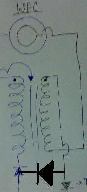
Guys some one was talking about Bi-filar coils before a friend sent me this: Check what Tesla says below keeping the WFC and a bi-filar inductor in context:
Tesla's "COIL FOR ELECTRO MAGNETS," patent #512,340 is a very special coil design because, unlike an ordinary coil made by turning wire on a tube form, this one uses two wires laid next to each other on a form but with the end of the first one connected to the beginning of the second one. In this patent Tesla explains that the double coil will store many times the energy of a conventional coil.[1] Measurements of two coils of the same size and with the same number of turns, one with a single, the other with a bifilar winding, show differences in voltage gain. These bifilar Tesla's coils can be explained solely on the basis of their electrical activity. A bifilar coil is capable of holding more charge than a single wound coil. When operated at resonance, the distributed capacitance of the bifilar coil is able to overcome the counter - electromotive force ( e.m.f.) normal to coils, inductive reactance.
Because of the electrical activity, a bifilar coil does not work against itself in the form of a counter - e.m.f., the potential across the coil quickly builds to a high value. The difference between the turns becomes great enough that the energy is practically all potential, at this point, the system becomes an electrostatic oscillator.
Minimal work is done in my radiant energy system due to the absence of wasted displacement currents. As small heat losses occur, oscillations are maintained by surplus charge generated by atomic catalytic reactions, energy is siphoned from the kinetic moments of these charges.. After an initial input of energy from an outside Very low energy expenditure allows power delivery to an electrical load over an extended time period without an external fuel supply source, the radiant energy electrical generator will operate as a very efficient device.
The parts highlighted in red seem very very relevant in WFC context. So bifilar inductors are worth a try.What do you think?? any ideas on how we should try it??
Also Could you check up on the following link and see if it actually works for a WFC? http://jnaudin.free.fr/html/parabifc.htm
- Reply #222 on: September 06, 2007, 03:17:48 AM :
Much of this relates DIRECTLY to my thread I posted soon before RAVI's 'coming out'. It deals with all this directly. "Stanley Meyer, please meet Stanislav Avramenko: Water as a fuel..." http://www.overunity.com/index.php/topic,2967.0.html
In regard directly to the Tesla bifilar patent and setup itself, I mention in the above thread a Mr. Milan Manchich. He used a flat Tesla pancake coil, and applied a HF voltage to the inner or outer wire of the pancake coil, and on the opposite wire of the pancake coil, he placed an 'Avramenko's Plug'. http://www.keelynet.com/energy/milan.htm Please see the thread directly for the links to Avramenko and the like.
Tesla was the KING of voltage POTENTIAL, so I think these paths of research are good to follow to potentially lead us to the best WFC control circuitry.
- Reply #228 on: September 06, 2007, 06:28:13 AM :
Maybe something interesting. This guy is using radiant energy to get the osscilation done.. en gets lots of radiant power. Works quite strange, but maybe he is on to something.
- http://www.youtube.com/watch?v=IFHejjzQJek
- http://www.youtube.com/watch?v=9Ps4omGNU54
- http://www.youtube.com/user/Jdub6d9
- Reply #230 on: September 06, 2007, 12:15:25 PM :
At only 22, cracked easy capture of cold electricity, no meter, no scope, no soldering iron, no nothing not even a theory. This boy will go far. I feel I have wasted my life. AM
- Gh. J., Reply #243 on: September 07, 2007, 08:54:36 AM :
WFC WHITE POWDERY COAT FROM CONDITIONING : http://www.youtube.com/watch?v=Rx2uEsbTt8Y
Aaron says its Calcium Oxide ; some ppl are trying to use Reverse Osmosis and distilled water for conditioning, but you don't have calcium mineral in them, so just use TAP water ONLY or collect water from free flowing streams could work better than tap water!!!
Seems logical to add EXTRA calcium to the water to speed up the layer forming. You can just buy it at the the pet shop. Used to add to RO water for fishtanks... Robert
- Gh. J., Reply #245 on: September 07, 2007, 11:26:48 AM:
Calcium Oxide coat is Aaron's presumption/deduction and he says it could be anything ! It hasn't been analysed ! There are a lot of mineral salts present in natural water.
It could be any oxide or hydride or an exotic combination composition ! Also to note that Aaron has conditioned at 10V 2 Amps for 2 hours straight non stop for an hour and not like the conditioning process which Ravi mentioned!
There is a possibility that with the increase in Amp process mentioned by Ravi, there are different kind of mineral / deposits layers formed on the inner tube surface! Don't know if Aaron used pulsed 10V 2Amp DC or straight. Ravi's was pulsed! So just be careful which process you follow! It's not just a layer that you need to create but the RIGHT kinda layer!
This could be proven if it works or not by Aaron himself if he checks for the difference in gas output, before and after the conditioning ! Gh. J
- Aaron, Reply #246 on: September 08, 2007, 05:50:16 AM :
SUCCESSFUL CONDITIONING NEWS!!!!!! WFC Conditioning does reduce Amp draw with the same gas generation!!
So guys just build dis n you'll know it works!! U have a replicated proof now!
Message: There is increase in production for same input. Actually, I will post msg about it. The amps reduce over couple hours by couple hundred ma's meaning that there is more restriction and gas "appears" to be identical. Didn't measure gas but with amps reducing with dial on variac same...same production for less.
- Reply #258 on: September 09, 2007, 08:17:56 PM :
Ok guys I have confirmed through my experiments that you need to take the tubes out of the water to speed up the oxide layer to form. My tubes are completely covered with a thin layer already with 2 water changes and 12v@ 1A pulsed. I put my tubes in front of a fan in between water changes. I change it approximately every 20 mins. I'll post some pics later once i have it thick enough. I am having problems with the positive tube rusting though. It gets a gold color that appears to be rust.
- Ravzz, Reply #261 on: September 10, 2007, 04:15:14 AM :
PostPosted: Sat Sep 08, 2007 1:04 am : I'm sorry about not being able to post out here!! You guys are doing good!
Please follow the overunity forum aswell........ there seems to have been a success with the conditioning reducing the Amp draw with the same gas production!!! http://www.overunity.com/index.php/topic,3079.0.html
The same questions are still being answered as to why this can happen!! Just build it follow the conditioning procedure and youre on!!........it works people....dont think too much about how or why it works.........IT JUST WORKS!!
we can ascertain whys or hows after you have a working prototype....the science can follow later. Please check the new updated Sept 4th D14 for the conditioning process I posted on this forum.
I've taken enough risk again posting on this forum.....dont let this technology die again! RAVI RAJU
- Gh. J., Reply #261 on: September 10, 2007, 04:15:14 AM :
I'm posting the pdf of BIFILAR chokes info on Aarons ideas of how it could be working on the WFC!! This is being posted with permission from Aaron
link to the forum: http://www.energeticforum.com/energy/972-stan-meyer-bifilar-chokes.html
Pl. register there to find more info on dis topic: Stan_Meyer_Bifilar_Chokes-Energiticforum_thread.pdf, 1193.96 KB, http://www.overunity.com/index.php?action=dlattach;topic=3079.0;attach=12657
- Reply #271 on: September 12, 2007, 03:32:57 PM :

the image was donated to Panacea-BOCAF.
- Reply #283 on: September 14, 2007, 09:37:47 AM :
I think it is not Calcium Oxide in my case as I also have tried conditioning with distilled water and seeing the oxide layer forming within an hour. As most sources say, it is Magnesium oxide that forms as a protective layer on stainless steel. Then again I am not sure. might be different coating using different procedures. When i used higher amps and tap water and water got hot, then the white calc formed was pretty nasty. It formed unevenly and at certain places even filled the whole gap between tubes. So i think it is Calcium from tap water when you overheat your tubes and effect is similar to the effect of usual water heater.
Anyways, had also a maybe silly thought of just making some test tubes and try to coat with different materials and see if the effect might be similar to conditioning.... havent put it into practice yet.
- Reply #285 on: September 14, 2007, 05:34:12 PM:
For the last couple of days I've been monitoring and adjusting the voltage and current while conditioning the tubes, always maintaining around 12.5 volts at 300ma, removing the tubes around every thirty minutes to dry them gently over a stove.
The oxide layer is now quite thick on the inner tubes and a greyish white, but whats interesting is that the more I condition the tubes the more frequent the larger hydrogen bubbles are becoming.
- Reply #291 on: September 14, 2007, 09:21:03 PM :
Well said RunningBare, I think a lot of people over stress on the need for the BUZ350, Probably because the name sticks in your head and is easy to remember, There is nothing special about it compared to any other 200v N channel mosfet.
- Reply #295 on: September 14, 2007, 11:03:24 PM :
I think the problem is with some folk seeing the mosfet as being part of the magic, when in fact the only true critical components are the coils and tubes, the rest is generic electronics, mosfets have extremely low gate current, but it would be possible to use a Darlington bipolar transistor in it's place so long as it has a fast switching time, as for the 555 timer circuitry, thats just convenience, you can provide a square wave at particular frequencies from a number of different sources.
- Reply #296 on: September 15, 2007, 12:30:33 AM :
I do think the mosfet might matter....At least as far as the drain source diode goes. I think your diode in the d-14 circuit needs to be faster than the mosfet blocking diode so the back emf pulse will stay in the loop and not go to ground.
The buz-350 has a reverse recovery time of 180 ns and the 32n20c has a reverse recovery time of 265 ns witch is slower. This should work fine in this circuit. Also, the 32n20 has half of the internal resistance .06 ohm so it should run even cooler than the buz-350..Looks like a good choice and it is cheap. Most ultra high speed diodes have a 50ns on time or less witch should work well in the d-14 circuit. The diode could somewhat effect the tuning of this circuit.
- Reply #297 on: September 15, 2007, 01:11:02 AM :
The back EMF from a coil of 100 turns on a ferrite core would be in microseconds to milliseconds, a delay of 180 ns would be insignificant.
- Reply #299 on: September 15, 2007, 03:15:57 AM :
message from ravi raju (via panacea-bocaf - which is one direction to send info to, anonymously or with your name):
Ask people on the forum to follow the Conditioning procedure that I gave as you get very uneven coat formation on the surface if you use High Amps for long periods....and when you go above 3 Amps theres a possibility of the coating flaking off...the bonding between layers would not be that strong....these layers form one over the other after every cycle of conditioning.......the small time high Amp conditioning gives you an uneven coat and the long time low Amp conditioning evens out this....more or less. The longer you use Low Amp conditioning the better the end outputs!
DONOT CONDITION ON A SINGLE HIGH AMP VALUE FOR LONG TIME.
You could end up blocking the space in between the tubes and you'll have to dismantle the pipes and start all over again. We dont yet know exactly as to what the coating comprises of! As there are some High Voltage discharges (Probably....reason...glow in the dark) they could be some very exotic alloy compositions formed....as the temperatures for a fraction of a second at the point of discharge go into thousands of degrees C.
- Reply #307 on: September 15, 2007, 04:26:55 PM:
since the whole thing is a resonance system in operation, it is ulikely that any specific configuration numbers, like power, frequency, pulse shape, plate thickness, plate size, tube size, and or plate/tube separation distance.....it is unlikely that these are immediately translatable to another device. Even one that appears to be identical.
Tuning is likely to remain an individual task, in terms of getting the given unit to operate. This is likely to be true, until the exact operational parameters are well understood. At that point..it is likely that broad levels of 'repeatability' can be achieved.
- Reply #326 on: September 17, 2007, 06:18:30 AM :
Guys, here comes a step by step for beginners of daves and Ravi's. More tests/snaps /videos coming, almost finished construction.
fwdwaterfuelcellsnaps.zip, 1238.4 KB http://www.overunity.com/index.php?action=dlattach;topic=3079.0;attach=12843
- Reply #333 on: September 17, 2007, 11:33:51 AM:
If you look in stan meyer tech brief document you'll he used two differnt mathods of electron extraction. The one you showed (in series with the cell) is the old method. It all boils down to extracting the electron from the water during the pulse off time.... it doesn't really matter how you do it. It stops the hydrogen and oxygen atoms from recombining before they leave the water bath.
- Reply #338 on: September 17, 2007, 04:07:27 PM:
Stanley reasoned that since his whole method is based on using ONLY VOLTAGE POTENTIAL, it would stand to reason to label one of his elements in his circuit an AMP CONSUMING DEVICE. Since he is seeing amps and voltage are separate things, and they MOST CERTAINLY can be separated, this explains the labeling.
Of course, the AMP CONSUMING DEVICE refers to any loads (preferably resistive loads) which use power in a normal fashion.
- Reply #348 on: September 18, 2007, 04:14:42 AM :
I was just looking at Stan Meyer's explanation of one of his cells on YouTube and it got me to thinking. He was discussing how a laser could be used to keep the oxygen and hydrogen atoms in an excited state so they could not recombine to form water. This, he said, would give off extreme heat/energy. This is what is done to gases to form plasma. They are subjected to high energy fields, i.e. microwaves, lasers, radio waves so the electrons cannot naturally stay within the atoms. Examples of this are the laser induced plasma channel and microwave plasma experiments on YouTube.
I think another example of what Stan Meyers is talking about is the Kanzius affect. So the radio waves cause the water to split with the salt serving as a catalyst. Once the water is turned into HHO and it is lit, it starts to attempt to combine back into water. This would usually lead to a small explosion and the recreation of water but that does not happen in the Kanzius experiments. Instead as the HHO attempts to form H2O it is unable to do this because the radio waves are exciting the gas and it is staying in a plasma state giving off 3000 degrees heat as Stan Meyer's said. Is anyone working on a Kanzius recreation?
- Reply #350 on: September 18, 2007, 05:55:36 AM :
Tesla Impulse Technology based patent for creating Ozone by using "pulsed DC" http://keelynet.com/tesla/00568177.pdf
now we are finally getting to the root of things, impulse tech. gerry vassilatos has written quite a bit about these fast interruptions of DC, pulsing them to a specific frequency, and what Tesla discovered he was able to accomplish.
- Reply #352 on: September 18, 2007, 08:36:14 AM:
Check d followin vid of hydrocars @ 20.9 watts!! >>>> 11V 1.9 Amps >>>>and still reducing!
He seems 2 have done it! http://www.youtube.com/watch?v=GXzTtm-QwtI Way 2 go mate! one winner >>> few more 2 come!
- Reply #371 on: September 19, 2007, 11:15:34 PM :
Gheller J that done for me by Gary and was posted by me on oupower :-) we have built that but had some problems with it so we modified it to this one which is exactly the same as the d14 circuit.
when you print it out you will need to mirror image it ie horizontal flip it
- Runningbare, Reply #378 on: September 20, 2007, 04:33:36 AM :
Very interesting, of course I had not considered the obvious, the tubes are in fact capacitors to the the current flow and since its straight DC or pulsed DC they will charge impeding current flow, so adding more tubes will not substatially increase current flow, only the initial current will be high at turn on until they reach potential.
btw, this can also be found in the "Stan_Meyer_Full_Data.pdf" page 230 paragraph 4.
- Gh. j., Reply #378 on: September 20, 2007, 04:33:36 AM :
JUST RECEIVED THIS FROM A VERY VERY RELIABLE SOURCE !! Gh. j.
RAVI_WFC_Bifilar_02.jpg, 314.98 KB, 1600x1200 ; http://www.overunity.com/index.php?action=dlattach;topic=3079.0;attach=12932
- Gh. j., Reply #397 on: September 20, 2007, 06:25:11 PM:
i'm sorry but if you are using the lawton circuit alone this will not do anything but limit current, the back emf is wasted, if you are going to use this whith out a use of a transformer you should use this circuit, therfor it does not wast the back emf as the first picture, if you was to use the first picture you pasted it would work fine with a transformer, but the second added diode is not doing anything, and the direction of the chokes must be hooked the right way.
using the same core means sharing a magnetic field, if hooked improperly you loose. the core inside the choke takes on a discharge effect, when sharing cores the discharge emf effect falls faster, it is better to use single cores so each chokes can fall at it's on electro magnetic field rate.
it is very important that the 3rd cycle of the transformer hits the chokes at a discharge level, if the transformer hits the chokes on the 3rd cycle and they have already been dishcharged caused by using the same core, then you loose again.
update.jpg, 12.64 KB, 315x391 http://www.overunity.com/index.php?action=dlattach;topic=3079.0;attach=12941
- Reply #406 on: September 21, 2007, 02:48:49 AM :
Found this patent that was cited in Meyer patent. Someone in 1974 who produced hydrogen with pulsed power. May be it will help us to improve the pulse system and VIC
3954592_-_stephen_horvath-1974.pdf, 669.3 KB http://www.overunity.com/index.php?action=dlattach;topic=3079.0;attach=12946
- Reply #416 on: September 22, 2007, 02:29:43 AM :
Found this Canadian patent of Stanley Meyer. Date : 1988 Title: ELECTRICAL PARTICLE GENERATOR. We saw a drawing (fig. 3) of a very special choke of "3 parallel non-magnetic tube". There are other kind of choke. I am not a specialist, but I think you shuold read it.
stanley_meyer_canadian_patent_01213671.pdf, 805.08 KB http://www.overunity.com/index.php?action=dlattach;topic=3079.0;attach=12969
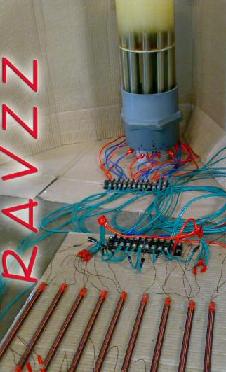
- Ravzz, Reply #421 on: September 22, 2007, 03:21:46 PM :
MULTIPLE BIFILAR SETUP for WFC!!
Im sending a pic of the multiple bifilars I tried on the WFC just a while ago. These were connected to each pipe individually. Diode used 1200 V 40 Amps. Solid core length 8" wound with 0.711 mm conductor end to end.
The generation increased by approximately another 10cc of gas for a 20 second period. This works on efficiency!! Need to try out other combos to see if it can increase some more.
- Reply #431 on: September 23, 2007, 10:25:33 PM :
It never hurts to rember that hydrogen is an alkali metal..and that H20 could sort of be considered to be it's 'oxidized state'
- Ravzz, Reply #441 on: September 25, 2007, 05:27:03 AM:
I think my tubes are still being conditioned as I saw a lot of brown stuff generation when I connected the bifilar inductors. The conditioning I presume happens for every specific voltage.
Try to use a ferrite core torroidal to step up voltage connect to the inductors (individual and regular wound) as mentioned by Spewing on Overunity thread as of now as the bifilars are creating some problems...I blew up both the 1200V 40A diodes....looks like one of the tubes ( no.7) has shorted...no gas production. The voltages might have gone very high with the bifilars connected and theres a possibility that this is creating problems for the smaller gap to short out. Dont use the bifilar inductors till we have a proper understanding of how they can stably work.
- Ravi_Bifilar_Gen_01.jpg, 1108.97 KB, 1021x1600 - http://www.overunity.com/index.php?action=dlattach;topic=3079.0;attach=13091
- Ravi_Bifilar_Gen_02.jpg, 1069.94 KB, 1329x1200 - http://www.overunity.com/index.php?action=dlattach;topic=3079.0;attach=13093
- Reply #489 on: September 28, 2007, 01:22:00 AM :
the transformer not under any kind of load should put out well over a thousand volts, the coils reduce current on both sides to the cell.. when the transformer starts to pulse the wfc threw the chokes the cell gets energized at that time, the cell is taking on a charge, during the off pulse of the primary side of the transformer the chokes is emitting back emf to the transformer witch is in parallel with both of the chokes "at that given time". by the time the 3rd pulse arrives the chokes work with the transformer in a series fashion, this multiplies the voltage across the cell.
each time the cell is step charged the voltage across the cell increases, each time the cell increases in voltage the output from the transformer to the chokes is increased, and stronger emf is emitted. once the cell reaches its peak the transfromer is now putting out over its maximum thousand volt rating because of the series positioning of the chokes. the second side of the circuit is now resonating, meaning the circuit, not the water fuel cell.
each time the cell takes on a step charge the amount of amps in pulses applied to the primary side of the coil drops, when the cell becomes completely charged hardly any amps is consumed from the primary side of the transformer.
this is not overunity, it is just a resonating "circuit" that works
- Reply #489 on: September 28, 2007, 01:22:00 AM :
--------------------------------------------- Return to the top
 -
-  -
-  -
-  -
-  -
- 
 ## by Ravi Raju, Stan Meyer's Replication by an Engineer in India http://www.panacea-bocaf.org/EngineerinIndia.htm

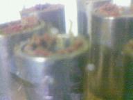
 021_pipes_setup_01s.jpg (141.41 KB, 640x480 - viewed 485 times.)
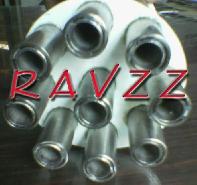
 034_pipe_setup_seated_in_base.jpg (160.15 KB, 480x640)