Feed Line No. 9 Article
COMPARING THE
HERTZ-WAVE AND TESLA WIRELESS SYSTEMS
by Gary Peterson
While speaking about his pioneering turn-of-the-century work in the development of the first practical system for wireless
telecommunications Tesla said:
". . . the apparatus which I devised was an apparatus enabling one to produce tremendous differences of potential and currents in an antenna circuit. These requirements must be fulfilled, whether you transmit by currents of conduction, or whether you transmit by electromagnetic waves.
You want high potential currents, you want a great amount of vibratory energy; but you can graduate this vibratory energy.
By proper design and choice of wave lengths, you can arrange it so that you get, for instance, 5 percent in these electromagnetic waves and 95 percent in the current that goes through the earth.
That is what I am doing. Or, you can get, as these radio men, 95 percent in the energy of electromagnetic waves and only 5 percent in the energy of the current.
The apparatus is suitable for one or the other method. I am not producing radiation in my system; I am suppressing electromagnetic waves.
But, on the other hand, my apparatus can be used effectively with electromagnetic waves.
The apparatus has nothing to do with this new method except that it is the only means to practice it.
So that in my system, you should free yourself of the idea that there is radiation, that energy is radiated.
It is not radiated; it is conserved." [1]
While they are in many
respects similar, there are also some
significant differences between what might be called the "Tesla wireless system" and the Marconi or Hertz-wave wireless system in common use today.
Both incorporate what is commonly called the "four-tuned circuit" configuration consisting of inductively-coupled radio-frequency circuits, two at the transmitter and two at receiver.
As Tesla made clear, the basic mechanism for producing the radio frequency power is essentially identical. The principle difference is in the antenna or launching structure.

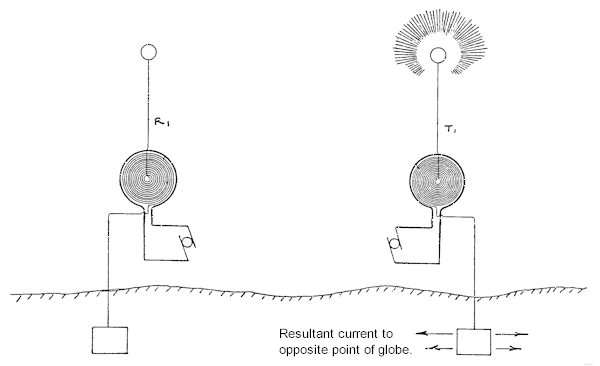
An illustration of Marconi's system showing its 1/4-wave monopole
transmitting antenna. [3] Both the transmitter, on the left, and the receiver
are of the original single tuned circuit design. Early on Marconi
redesigned his transmitter using Tesla's coupled tuned circuit invention,
while retaining the monopole launching structure.

The Tesla system with coupled tuned circuits at the transmitting and
receiving ends. The unit on the right is acting as the transmitter. [3]
For our purposes, we will use a power source with a frequency of approximately
136 kHz. This frequency falls within the 135.7 - 137.8 kHz
low-frequency amateur radio band which presently exists in Europe and the
U.K.., and has been proposed in the United States [4]. The relationship between wavelength and frequency is
given
by the equation,
lambda (in feet) = 984 /
frequency (in mHz).
Doing the math, the electrical
wavelength at 136 kHz is about 7,235 feet. A vertical quarter-wave Marconi-type antenna might consist of a
metal radio tower reaching about 1,800 feet above the earth's surface.
A Tesla-type transmitting
tower for this frequency will be much shorter than the monopole. The bottom third or so consists of a helical resonator followed by a relatively large conducting cylinder connected to a spherical or
donut-shaped terminal of large surface area. At 136 kHz a realistic height for
such a structure is on the order of 90 feet.

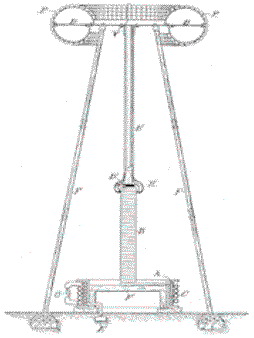
Tesla revealed this
configuration in U.S. Patent No. 1,119,732, "Apparatus for
Transmitting Electrical Energy." [5] The 187-foot Wardenclyffe tower
on Long Island embodied the same design.
The problem is to characterize the performance of these two different
launching structures in response to
the application of radio-frequency alternating current.
In the first case antenna theory tells us, with proper coupling of the
transmission line to the structure will be an efficient radiator of electromagnetic energy.
Because of the finite velocity of the electric current flowing through a
conductor, it takes a finite amount of time for the applied charge to build up on the antenna.
The electric field follows the charge carriers moving along the vertical monopole antenna and the lines tend to spread out
through space toward the position they would occupy under static charge conditions.
[*] During the next quarter cycle, the monopole is discharged and some of the lines break away to form closed loops.
The field lines propagate out into space in somewhat the same manner as waves are formed on a pond when a pebble is thrown in.
This action is repeated with each successive RF cycle. The implication here is that energy is irretrievably lost from the monopole.
This lost energy represents electromagnetic radiation, that is to say, radio waves.
Along with the field energy lost or radiated from the monopole, a certain fraction
returns back to the source during each RF cycle.
Consequently, the fields near the antenna represent both energy storage and radiation components.
These are described as the reactive fields and the radiated fields of a
radio antenna.
In the case of the Tesla-type launching structure the
time delay effect
that is responsible for the production of electromagnetic radiation or
"radio waves," such as occurs with a quarter-wave monopole radio antenna,
is minimized and the stored-energy or reactive component of the field is greatly increased.
While the amount of time expended to charge the structure remains the same, the overall distance between the bottom feed-point and the structure's upper extremity is much smaller.
For example, if the structure is 90 feet in height, when compared with the
1,800-foot tall monopole the greatest overall distance the wave disturbance
moves axially along the resonator is about 5 percent of the
136 kHz electrical quarter-wavelength. The field lines distributed throughout space follow the
charge variations much more efficiently. This means that once the polarity of the RF source
is reversed a greater amount of the energy field is
recovered or reflected back from free space to the transmitting element and electromagnetic radiation
is suppressed.
The base impedance of the helical resonator of a properly configured Tesla magnifying transmitter is very low and this allows the
recovered or reflected power to be efficiently applied directly to the earth via what
must be a very robust ground connection for optimum efficiency.
A considerable expenditure
might be expected for the above-ground antenna structure of a
Marconi-type long wave wireless facility, if it is to perform efficiently;
installing the buried counterpoise is not as expensive a proposition. The opposite
is the case if the construction of a proper Tesla World Wireless system magnifying transmitter
is
undertaken.
Again quoting Tesla:
"You see the underground work is one of the most expensive parts of the tower. In this system that I have invented it is necessary for the machine to get a grip of the earth, otherwise it cannot shake the earth.
It has to have a grip on the earth so that the whole of this globe can quiver, and to do that it is necessary to carry out a very expensive construction.
I had in fact invented special machines. . . ."
In conclusion, fundamentally identical electrical oscillators consisting of an RF
power source, an elevated conductor and a robust ground connection can be configured in ways which are conducive two different forms of wireless propagation.
Low frequency wireless communications can be accomplished by the production of either electromagnetic radiation in the form of space waves, or the production of ground currents and accompanying trapped surface-waves
possibly similar to the
Zenneck surface wave.
Once again quoting Tesla,
"From my circuit you can get either electromagnetic waves, 90 percent of electromagnetic waves if you like, and 10 percent in the current energy that passes through the earth.
Or, you can reverse the process and get 10 percent of the energy in electromagnetic waves and 90 percent in energy of the current that passes through the earth. . . .
This view, by the way, is now confirmed. Note, for instance, the mathematical treatise of Sommerfeld,
[6] who shows that my theory is correct, that I was right in my explanations of the
phenomena. . . ." [1]

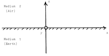
Figure 1. Geometry for
Zenneck wave propagation. [7]

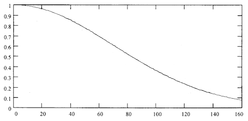
Figure 8. Zenneck wave field strength decrease for round the world propagation as a
function of frequency in kHz. [7]
[*] Antenna Theory and Impedance Matching
A radiating dipole field is due to a collection of charged particles oscillating in a conductor comprising a launching structure.
The charge is forced into oscillation by the injection of electromagnetic energy.
This process involves impedance matching of the energy source and the
launching structure, as well as the transmission line connecting the
two. The oscillator trades this energy back and forth between its inductive [magnetic] and its capacitive [electrostatic] energy storage components.
Periodic movement of the charge sets up a sinusoidal E-field and cosinusoidal H-field.
The H component carries the magnetic energy and the E component carries the electrostatic energy.
During the oscillation of the charge/field, it's stored energy alternates between a magnetic peak and an electrostatic peak.
The oscillation occurs at a fixed frequency primarily dependent upon the geometry of the
launching structure and to a lesser extent the proximity of any surrounding objects.
The process of dipole radiation also involves impedance matching, in this
case that of the dipole oscillator to the impedance of free space, which is
E/H = 377 ohms. The E/H impedance ratio of the dipole field is determined by the magnitude of
source charge and distance through which it oscillates. The EM wave travels outwards and, encountering the free-space
impedance, some portion of the radiated power is reflected back to the launching
structure due to more or less of an impedance mismatch. The
remainder continues to radiate away from the antenna, escaping in the form
of electromagnetic Hertz
waves (see Teaching
Electromagnetism Using Advanced Technologies).
The Hertz-wave transmitter
launching structure provides a good initial match with free space
resulting in the efficient production of electromagnetic waves.
The Tesla-type launching
structure is specifically
designed to have a poor impedance match with free space. Its
configuration inhibits the launching of electromagnetic space waves.
Provided with sufficient input power, a large magnifying transmitter is
capable of breaking down the insulating medium constituted by the denser
portions of the earth's atmosphere around and above it.
References
1)
Nikola Tesla On His Work With Alternating
Currents and Their Application to Wireless Telegraphy, Telephony and Transmission of Power
2) "The True Wireless"
3) "The Disturbing Influence
of Solar Radiation On the Wireless Transmission of Energy"
4) Notice of Proposed Rule Making, FCC 02-136, 05/15/2002
5) Dr. Nikola Tesla — Complete Patents
6) Uber
die Ausbreitlung der Wellen in der drahtlosen Telegraphie," [Annalen
der Physik, Vol. 28, March, 1909, pp. 665-736. ["Propagation of Waves in Wireless Telegraphy," Arnold N. Sommerfeld, Ann. Phys. (Leipzig), 28, 1909, pp.
665-737.]
7)
Corum, K. L. and J. F. Corum, "The Zenneck Surface Wave,"
Appendix II of "Nikola Tesla, Lightning Observations, and Stationary
Waves," 1994. (See Q&A No. 39 "Can you explain, within accepted laws of
physics, what was Tesla doing in Colorado Springs and on Long Island?"
for excerpts.)

"Electromagnetic
Surface Waves," in Advances in Radio Research. J.A Saxton, editor,
Academic Press, Vol. 1, 1964, pp. 157-217.
Burrows, C.R,
"The Surface Waves in Radio Propagation Over Plane Earth,"
Proceedings of the IRE, Vol. 25, No.2, February, 1937, pp. 219-229
Yu. V. Kistovich,
"Possibility of Observing Zenneck Surface Waves in Radiation from a
Source with a Small Vertical Aperture" [Soviet Physics Technical
Physics, Vol. 34, No.4, April, 1989, pp. 391-394.
Schelkunoff, S., and H.T. Friis, Antennas: Theory and Practice, Wiley, 1952, pp. 352-353; 252.
Hill, D. and J.R Wait,
"Excitation of the Zenneck Surface Wave by a Vertical Aperture,"
Radio Science, Vol. 13, No. 6, November-December, 1978, pp. 969-977.
World System
characteristics, regulation, ethical considerations; requirement for
eternal vigilance
Regeneration Revisited:
". . . Rudenberg teaches that the
antenna interacts with the incoming field, which may be approximately a
plane wave, causing a current to flow in the antenna by induction. The
[antenna] current, in turn, produces a field in the vicinity of the
antenna, which field, in turn, interacts with the incoming field in such
a way that the incoming field lines are bent. The field lines are bent
in such a way that the energy is caused to flow from a relatively large
portion of the incoming wave front, having the effect of absorbing
energy from the wave front into the antenna from a wave front which is
much larger than the geometrical area of the antenna."
'Energy
Sucking' Radio Antennas: ". . . light waves are
about 5000 Angstroms in wavelength, while atoms are more like 1 Angstrom
across. How can such tiny "antennas" absorb and emit such long
waves? Usually it takes a half-wave antenna to do this. I never
encountered a good explanation for this during my physics education.
It turns out that the explanation is both little-known and fascinating. .
. ."
Global resonance may be achieved with an expenditure of
at least 37 kW of peak envelope power to the launching structure.
(746 watts = 1 horsepower)
Interplanetary communications
". . . with the novel means, proposed by myself, I can readily demonstrate that, with an expenditure not exceeding two thousand horse-power
[1.492 MW], signals can be transmitted to a planet such as Mars with as much exactness and certitude as we now send messages by wire from New York to Philadelphia. These means are the result of long-continued experiment and gradual improvement." -- Collier's Weekly, February 19, 1901
InterPlaNetary Internet
Project defining the architecture and protocols necessary to permit
interoperation of the Internet resident on Earth with other remotely
located internets resident on other planets or spacecraft in transit.
(See Interplanetary Network Connects Rovers, Orbiters, Agencies and Earth.)
Establish a world system on Earth.
System transmitters would serve as Ground Station
One (GS1), with a similar world system on Mars, bypass orbiting repeaters, facilitate continuous connectivity on
and between both planets.
Communications with spacecraft to be investigated.
band-width problem: wave complex, frequency division
multiplexing
propagation delay problem: (?)
|
![]()