
 |
|
|||||||
| Homepage | Energetic Science Ministries | User CP | FAQ | Calendar | Search | New Posts | Mark Forums Read | Open Buddy List | Log Out |
| Renewable Energy Discussion on various alternative energy, renewable energy, & free energy technologies. Also any discussion about the environment, global warming, and other related topics are welcome here. |
 |
|
|
LinkBack | Thread Tools | Search this Thread |
Rating: 
|
 03-28-2012, 02:02 AM
|
||||
|
||||
|
measurements
UFO,
Hey UFO, I do have a nexxtech from the source, maybe you can tell why I can measure capacitance, and ohms but I don't get a reading for amps or volts or frequency, its on, but no reading, I fried something I guess. This just happened last week. So now all I have is an inductance capacitance meter, a nexxtech cap and resistance meter, a micronta ohm, ac/dc volt, and dc milliamp meter, and an EXCEL digital clamp meter that measures ac current, volts and ohms. If I can't get the frequency for the nexxtech working I will buy a new one, or two. I mearured the coil UFO, it was 2.1 ohms, I used wire from the source ( was radioshack once) 22 ga I wound 4 layers around a 1 inch plastic pipe, each layer had 100 turns. Thug           


|
|
03-28-2012, 03:29 PM
|
||||
|
||||
|
Sorry about your meter (R.I.P)
ORR
Quote:
Sorry about the meter...I fried many also, so don't feel bad... However, they were in their warranty period so...the Ex-Tech was Ex-changed... Related to the Coil, YES!!..that is a great specification for our purposes... Now, a thicker gauge like 18 awg, would be even better...and if you could do it with a Double Stranded wire...(Bifilar), but in parallel not like Tesla's ... then you would really see "The Light"... Now you said you wound it around a plastic pipe...that's great, but try inserting a solid steel bar, just the exact size of the Coil length and leaving a small air gap between ...This will reinforce Radiant Field way more. You will have her more robust and much less expense from your Hot side. Cheers Ufopolitics
|
|
03-28-2012, 05:16 PM
|
||||
|
||||
|
winding coils
ufo,
I unwound an old alternator last night and I now have a whole lot of wire which looks a little bigger then the 22 ga., it must be 18-20ga. So, since I'm starting from scratch with this coil, should I bother to layer it or just wind one long coil, and should the bifilar be wound together, or on top of each other. Also, should bifilar be diferent size wires. I was also going to wind this one on a 2 inch pvc pipe, have you found a certain size diameter too big or bigger the better. The one inch pipe was just right for rolls of dimes,so i tried a solid silver core (90%silver dimes), there was an effect, i just need to go back and observe. A solid steel rod did have effect, but again, I should go back and observe more. Anyway, I will wait to here from you before I start to wind new coil. Thug
|
|
03-29-2012, 04:21 AM
|
||||
|
||||
|
UFO,
Just couldn't wait, so I wound 450 turns, 6 layers, of the wire I salvaged last night. I wound it on top of the original 400 turn. I also left the 3rd and 4 th layer connections exposed to try step down. Will try connecting as bifilar like you posted earlier in thread. I'll measure ohms etc later on. Thug
|
|
03-29-2012, 09:43 AM
|
|||
|
|||
|
Hi Thugugly,
Thanks for the advice to use a different batt for the power supply, it works well and no more blown components. HI Ufo, I have made the coil. Plastic tubing 48mm diameter. 375 winds of 19AWG .9mm diameter, 3 layers. Solid Bright Mild Steel core. The circuit seems to be working well although I don't know what the wave form is like because I don't have an oscilloscope. I can tell that the frequency and duty cycle are working. netica
|
|
03-29-2012, 01:58 PM
|
||||
|
||||
|
Coil...
Quote:
I am sorry I have been out... You could layer it "normally" , meaning one layer winding down to bottom, then, next coming up to top, and so on, up-down. Bifilar in parallel I meant by just two strands of wire, same gauge...or very close ones in gauge...(18-20) The two inch PVC is just fine, I mean do not overheat it...or it will soften on you.. Should not exceed the diameter going too big for the amount of wire you will have, remember the magnetic effect starts at the inner walls going towards the center of core...if it is too wide, then it will be an inactive, meaning, no effect in the center... A solid Steel rod or any magnetic material will do the effect of the enhancement of Radiant Field. There should be a small millimeter air gap between...meaning NOT too tight Regards Ufopolitics
|
|
03-29-2012, 02:07 PM
|
||||
|
||||
|
UFO,
I hooked up coil and it lit 4 neons up brightly, I have not played with it yet, but I checked current at battery and it was only drawing 200-300 ma. I have to go to work now but will try some things later, if I can stay awake. Thug
|
|
03-29-2012, 02:12 PM
|
||||
|
||||
|
Quote:
Winding it on top of the other will work just fine...try exciting the primary you wound (inner)...and connect output in secondary...you will get Radiant induced in it...actually in both will be output... Bifilar coil should reduce the Ohms a lot...try to keep it in the lows 1-2 Ohms on primary... Inner Core Secondary you could do finer wire and more turns-ohms... Now exterior winding on top of Primary, should be of similar wire to avoid transfer loss.. Observe outputs with, and without rod... Radiant Induction occurs from Outside-Towards Interior of Core, however, winding a secondary (same or very close awg) right on top of primary, will be induced, but not separated by an exterior plastic core, it will not induce then. I use just masking tape or higher temp tape, between layers or to wind exterior secondary. Regards Ufopolitics
|
|
03-29-2012, 02:17 PM
|
||||
|
||||
|
Great!
Quote:
Great Netica! I am glad you have it running by now!! Connect Neons and CFL's on Output...of 23-40 Watts (Real Watts not what they "replace") and observe brightness as you tune up...go slowly, don't rush it to max... The Coil is excellent now! Regards Ufopolitics
|
|
03-29-2012, 02:53 PM
|
||||
|
||||
|
Low Ohms...
Quote:
You know low resistance on Coil will put heavy stress in your oscillator...so make sure you protect them with diodes to avoid heavy negative spikes ...and watch for not going too close to linear signaling (meaning too short T-Off's) So, do NOT accelerate "Full Blast" and keep it like that for too long periods...I know you do not have a Hertz-Scope to read..so go by "ear"...and keep checking Mosfet's temperature...I have heavy heat sinks as also Bus Bars to Drain, and a small cooling fan on top of circuit... Regards Ufopolitics
|
|
03-29-2012, 11:44 PM
|
||||
|
||||
|
Did you check the Meter contacts?
Quote:
Related to your meter: Did you take it apart and went to the rotary-Selector switch contacts? If it is an EXTECH, is just a few small Philips bolts...away. Normally that's their "weak" point...however the board that have the contacts is all the way inside the meter. If you get lucky...they may just be dirty...or if it was Radiant beam...it just melt them away from the fiberglass board... Both ways they are repairable.. not a piece of cake...but could be done... And could check if parts are available for it... Regards Ufopolitics Last edited by Ufopolitics : 03-30-2012 at 12:29 AM.
|
|
03-30-2012, 07:20 AM
|
|||
|
|||
|
Quote:
Connected a 110v neon, with an input of 38v the neon flashed purple a few times then turned red then got so hot it started burning some paper on a note book it was lying on. Tried another with 8.4v flashed purple for longer no matter the frequency I tried but it was lower frequency's not to high. Still ends up heating up then going red, the glass on the neon blackens. With the CFL it's rated at 240v 24 watt ( I tried this earlier with my other coil but called it a neon by mistake sorry about the mix up ) using 38v, I got it to flash from slow to fast until it finally glows quite bright but nothing out of the ordinary, I used different duty cycles and frequency's. The coils core gets quite hot. That's about it for now netica Last edited by Netica : 03-30-2012 at 08:58 AM.
|
|
03-30-2012, 02:25 PM
|
||||
|
||||
|
Hello Netica
Quote:
Netica... You are "dialing too fast"...give it time when going up...don't rush to max, top lighting...There is a point where you get (in Neon) just purple light flickering...stay there. don't go up and observe parameters...frequency and voltage consumption. Related to the CFL, also you are going too fast to observe "differences" from "Normal and Radiant Glow" . There is a point on CFL , where you are supposed to get a very fast pulsing that almost disturbs your sight, it turns from green to purplish color...because the wave amplitude... Quote:
Quote:
The flickering Purple light ball, moving up-down on electrodes is definitively Radiant, the normal steady Orange Glow on Cathode-Anode is Hot...having both currents at High Outputs will definitively get component HOT and burnt... The reason of installing a Pot is to "GRADUALLY" increase output SLOWLY...and when noticing the purple is gone...then STOP...or keep going and burn it. You are getting the Coil too hot, just because the same thing I wrote before...You are rushing it and staying on the High Side for too long. This Oscillator is NOT a perfect one...to get Radiant, however, works fine UP TO A CERTAIN LEVEL ONLY...after that it increases T-On's and decreases T-Off's as ANY normal controller DOES...that FACT kills Radiant ENTRY at too High Dialing ... AGAIN, Radiant ENTERS AT T-OFF TIMES ONLY. Did you try running a DC Brushed Motor on this output? Please do. And do it calmly ...do not rush it. Cheers Thanks Ufopolitics Last edited by Ufopolitics : 03-30-2012 at 02:28 PM.
|
|
03-31-2012, 08:10 PM
|
||||
|
||||
|
motor
Hi UFO,
I havn't had a chance to really sit down with the circuit, I have been scrounging for a motor, and I found an old drill. So I'm curious, before I start to hack, is this brushed motor ok. It's a universal I thought, but I would like to hear your opinion and any additional information you care to share. One thing I quickly did, was to input, to the slightly larger outer coil, then use the smaller inner wire with slightly less turns as well, as secondary. The coils were not physically connected to each other. I connected neons across both coils ( cold side of diodes on each coil), and neons lit brightly. Adding an iron core decreased output. Also, when I connected 21v input it was very intense, as in cook the neon buy itself across primary cold side. I'm curious, I was using 1 nf cap in timing circuit, I thought would go from 1 to 60 khz but there was output through the whole range of frequencies, so I couldn't start slow, I mean I will try larger caps but I was just curious if that sounded right. Also, as off time was increased, definitely there was increase in intensity of output. Thug
|
|
04-01-2012, 04:34 PM
|
||||
|
||||
|
That is a good motor, Thug
Quote:
Yes, that is a great motor to test here...brushed motors will show you there are barely sparks at commutator, and it will run cold. Now related to what you did there... I am not quite sure if the secondary you are talking about is Internally set-related to Primary- , since you wrote : Quote:
The thing is by doing that you are decreasing the Hot Induction, therefore minimizing the general output..you unbalanced inductions there. Both Inductions should be balanced, meaning an inner bar without some external (to primary) steel frame, will decrease output. Now ,you do should be able to regulate the Pot slowly...that is a problem. Do you have a 250K Pot plus the two 1K at each sides of Pot? Definitively you have it right when decreasing T-Off it does increase output. Could you supply some pic's and diagrams of your set-up? Thanks Ufopolitics
|
|
04-01-2012, 06:47 PM
|
||||
|
||||
|
ufo,
I was hoping that would be a good motor, i think i have an old dc drill as well, thanks. The coil,sorry, that was just the inital coil i had 400 turns of 22 ga., then i wound the 18-20 ga over it. i was going use the outer coil for secondary and connect as bifilar (with + secondary, to - primary, then the output to the motor, as you posted earlier in thread). I just wanted to try getting cold side to light on each coil before i hooked together as bifilar, which did lite the bulbs on both coils, and with 21 v was very intense. there just did not seem to be a range with the 1 nf where it did not light the bulbs, thats all. since radiant flows toward center the inner coil wound seem better as secondary, so i tried it and it lit well. i was just fooling around, mainly i was trying to get a motor and now i have one, so i will start working on that and experimenting. i will try it as inductance only hooked across secondary, and with the coils connectd as a bifilar. Also can't wait to see your next video, you mentioned anti-gravity, can't wait. thank you for your help, thug
|
|
04-01-2012, 07:19 PM
|
||||
|
||||
|
Quote:
I thought it was supposed to be just as long as coil. once i get motor mounted on something i will try different cores and setups. thug
|
|
04-02-2012, 12:35 AM
|
|||
|
|||
|
In reading over this thread it appears that variable frequency with a variable pulse width is required. The 555 is a neat little chip and has many uses and it can do this, but it rather awkward to vary pulse width and frequency independent of each other.
The following is a simple circuit that will allow frequency to be changed and yet have the percentage of ON time of the pulse width to remain the same, and varying the pulse width will have no effect on the frequency. 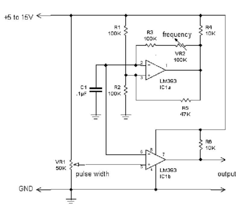 Circuit operation: IC1 is a ½ of a voltage comparator wired as a conventional square wave oscillator, its frequency is controlled by C1 and VR2 these values can be changed to suit the frequency range you want. However its square wave output is not what were interested in but rather the sawtooth voltage that is produced by the timing capacitor C1. This voltage is then feed down to one of the inputs of the other half of the IC1. Its other input connected to a voltage divider pot VR1. By varying this voltage you choose what portion of the sawtooth that will used to turn ON the output of the IC. This gives complete control over the pulse width from 0 - 100%.
|
|
04-02-2012, 05:38 AM
|
||||
|
||||
|
Quote:
Excellent and simple circuit!!
|
|
04-02-2012, 06:40 AM
|
||||
|
||||
|
Mad Scientist
Very neat circuit , thank you ! Please forgive my question but what is the shape of output square wave ? Is that sharp with abrupt fall/rise edges or the time response of this circuit is too slow to create good square wave output ? I have no deep experience with electronics but 1.4uS response time for this comparator chip took my attention.  I think we are looking for the most simple circuit for everybody to replicate yet with excellent results with production of radiant energy. I think we are looking for the most simple circuit for everybody to replicate yet with excellent results with production of radiant energy.
|
|
04-02-2012, 11:26 AM
|
|||
|
|||
|
Hi Ufo,
I have been trying some different brushed motors and I have been getting them to run, some better than others, they tune differently. I tried adding capacitors after the diodes as thugugly has mentioned and with all motors adding capacitors make them run much better. I don't believe I am getting the radiant energy in properly, the energy comes in on the T- Off but motors still run warm, and I can't get the radiant energy increase when decreasing the on time and increasing the off time in each cycle. I may now add a secondary coil wired as you have described to see what differences it makes. netica
|
|
04-02-2012, 12:07 PM
|
||||
|
||||
|
Antigravity Effects Of Radiant Energy
|
|
04-02-2012, 01:19 PM
|
||||
|
||||
|
Your Diodes may be the problem...
Quote:
Yes they do "tune" different, like there is a "spaced delay" in response...right? Well, of course the Caps after diodes will create a "more realistic-direct effect", since the Capacitors will be 'filling in' those empty spaces-of the time-on's... Quote:
Meaning, You are getting also too much Hot there...that creates the Heat...and the Odd to RE effects you are getting. Your "Cold Side" should be mainly based on the Off-Time Pulses...and very reduced On-Times...If You get too much Hot...then T-Off's will be much lower. Give a try to the IN4148/Radio-Shack 1N914 Crystal Diodes...they do filter so good your meters will not read at all, (I had post that fact here in previous posts) However, they are not good standing Too High Currents...So, ...do NOT accelerate like you like to do...  The other thing you could do, is to add the 1N4148 after your diodes, as a second filter to do the Final Clean up from Hot...I have done that with great results. Meters will read crazy though... Cheers Ufopolitics
|
|
04-02-2012, 03:52 PM
|
|||
|
|||
|
Quote:
|
|
04-02-2012, 11:28 PM
|
||||
|
||||
|
Steel Bar...correction
Quote:
Hello Thug, I said "Internally" secondaries, meaning inside the plastic core of primary...that is when everything changes, and if you get a steel bar there it will decrease that Inner Secondary Output...that was what I was referring to. Now, If you are talking about just winding one coil on top of another, divided by tape...then, applies a steel bar the size of the core length ...that will be enough, and should not decrease the output...If it does, then a possible cause is that bar needs to be closer to the walls (too big of an air gap)...but it could be others...like the material being too "Magnetic Memorized"...or already magnetically oriented...against Radiant direction...(try turning it) The thing is...Radiant also need Hot Induction to Thrive...when we have just one coil on top of the other, separated by tape or else...Induction of Both Currents will be "Directly Sharing" the steel bar... This changes once you get an Inner Secondary of several turns of finest wire (I have used 33 awg 4000-8000T)turned in a separate thinner plastic-fiberglass core inside the primary core...This set Up..I have not finished the video yet, but it is coming...right now it will complicate things...sorry for my confusion...and bring it now. The "Perfect Steel Bar" for all related applications here, must NOT have Magnetic Memory (remember this core is constantly changing magnetic polarities, it will stress the steel molecules)..I heated mines to flare orange and sink it in cold water...that took care of overheating problems, magnetizing and performance... Cheers Ufopolitics Last edited by Ufopolitics : 04-02-2012 at 11:37 PM.
|
|
04-03-2012, 06:44 AM
|
||||
|
||||
|
Quote:
Flexible oscillator and flip-flop oscillator is a MUST for US.
|
|
04-03-2012, 04:49 PM
|
||||
|
||||
|
LM393 Dual Voltage Comparator...
Quote:
This IC (LM393) a dual voltage comparator, has also been cited here in post #213-214 by member kapierenundkopieren, and Me, but working together with a 555 IC... In Your circuit , which looks lot simpler than previews one, LM393 plays as an oscillator, without the need of 555...that's great!! However, we are looking here ,to be able to (as we turn on volume) to decrease T-On and increase T-Off (Duty Cycle starting at 50-50% [T1-T2], going towards 40-60, 20-80 and so on, considering T1 as T-On and T2 as T-Off... And I see we can do that in your circuit, that's also great. However, We also need to be able to pulse both ends simultaneously, positive and negative drains, by means of Dual Channels of P and N Channels MOSFET's (I have done it with two 555.. working one as oscillator, regulated by the pot, and the second IC555, being just an "Inverted Image" in Anti-Phase of IC555(1), so, this creates a simultaneous, High-Low signal to P and N Channels... However in my circuit I can not regulate Duty Cycle...I have to arrange that... I know we are getting close to obtain a great SPECIFIC oscillator for this purposes...which differ from typical oscillators in a complete turn of 180 degrees... I see this chip (LM393) as a great subject for this new type of oscillator. The last and wonderful thing we need to do is to ISOLATE the low voltage signals from Oscillator to Gates, from the Source-Drain Higher Voltage that also needs to be regulated to higher levels...where I plan to use an Opto-isolator chip, to do this job. Conclusion: We need very short timed ,but very high peak levels (Voltage) of pulses of both Positive-Negative going to the Coil...starting with 50% dt and running up to 20-80% dt where (T1[On]=20%) and (T2[Off]=80%) or more even to 10-90... I know this type of oscillator will not control a motor...When we increase "volume" motor will start stalling , making sudden turns of very high RPM's...but stopping every time off..till it will barely move...makes no sense right?...Well, for Radiant we need this type of oscillation... Regards to all Ufopolitics
|
|
04-03-2012, 07:42 PM
|
|||
|
|||
|
Quote:
To do that just add a second IC and use ½ of it as an inverter and the other half as a buffer this will give two outputs that are 180 degrees out of phase with each other. 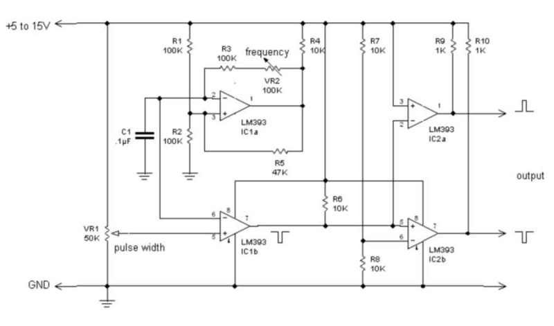 Note: One LM339 can be used in place of the two Lm393s, as it is the quad version of the 393. The 555 is a great little chip, with untold uses, but trying to do this with it is an exercise in learning how to tear your hear out. 
|
|
| Currently Active Users Viewing This Thread: 13 (2 members and 11 guests) | |
| lamare, Bob Smith |
| Thread Tools | Search this Thread |
| Rate This Thread | |
|
|


