Energetic Forum  

Go Back   Energetic Forum > Energetic Forum Discussion > Renewable Energy
Homepage Energetic Science Ministries Register FAQ Calendar Search Today's Posts Mark Forums Read

Renewable Energy Discussion on various alternative energy, renewable energy, & free energy technologies. Also any discussion about the environment, global warming, and other related topics are welcome here.

Reply
 
LinkBack Thread Tools
  #391 (permalink)  
Old 04-28-2012, 03:07 PM
cinan cinan is offline
Member
 
Join Date: Dec 2011
Posts: 58
Quote:
Originally Posted by aaron5120 View Post
Hi Cinan, I am interested in your more advance version. But I rather prefer to buy the board already wired and programmed from you, since I am an illiterate in microcontroller programing. Give me an e-mail address to which I can write to you, please.
You are of very good help here, indeed.
I plan to build a big coil to try replicating ufopolitics's discovery.
aaron5120
Hallo AAron,

There is one problem. If SW update come out, you need to update it and for that you need programmer anyway.... Its really very simple and I can issue step-by-step instruction for that..... Also connection can be made on universal PCB break board. If you have little soldering skills, no problem...

Cinan
Digg this Post!Add Post to del.icio.usBookmark Post in TechnoratiFurl this Post!Live Bookmark this Post!Google Bookmark this Post!Yahoo Bookmark this Post! share on MyspaceShare on FacebookTweet this thread
Reply With Quote
  #392 (permalink)  
Old 04-28-2012, 03:33 PM
aaron5120 aaron5120 is offline
Member
 
Join Date: Apr 2007
Posts: 62
Quote:
Originally Posted by cinan View Post
Hallo AAron,

There is one problem. If SW update come out, you need to update it and for that you need programmer anyway.... Its really very simple and I can issue step-by-step instruction for that..... Also connection can be made on universal PCB break board. If you have little soldering skills, no problem...

Cinan
Hi Cinan, please provide the step-by-step instruction of the software programing and all the shcematics for the advance version. If that may cost me some bucks it is OK, for it is your professional work, man.
I can solder it over. What I cannot do right now is to program the microcontroller. I need to know which hardware to buy in order to upload the program to the PIC, etc. This is a learning curve, and please bear with me, I am already 54 year old!
Digg this Post!Add Post to del.icio.usBookmark Post in TechnoratiFurl this Post!Live Bookmark this Post!Google Bookmark this Post!Yahoo Bookmark this Post! share on MyspaceShare on FacebookTweet this thread
Reply With Quote
  #393 (permalink)  
Old 04-29-2012, 12:58 AM
vrand vrand is offline
Senior Member
 
Join Date: Jul 2008
Posts: 398
Quote:
Originally Posted by Ufopolitics View Post
All other tests related to water resistance and shocks versus skin effect, I have done plus also a very clean Electrolysis in Salt Solution.
Hi Ufopolitics,

First off, I would like to thank you for sharing your very interesting research into Radiant Energy. The videos of your devices in action really helps explain this unique energy and its potentials as does your posts here on this forum.

I had some questions on your research into electrolysis with Radiant Energy.

- What type of electrolysis gas production was produced when using Radiant Energy (RE), compared to conventional "hot" electricity? Similar gas output productions?
- Estimated Volts & Amps input to the cell electrodes? Plate sizes and spacing?
- Did hydrogen & oxygen gas evolved off the plates, other gases such as water vapor?
- What was the temperature of the electrolyte salt solution over time? Did it become colder?

We all look forward to your experiments with the coils, in running motors, and other ways in utilizing Radiant Energy.

Keep up the good work!

Cheers,
Mike
Digg this Post!Add Post to del.icio.usBookmark Post in TechnoratiFurl this Post!Live Bookmark this Post!Google Bookmark this Post!Yahoo Bookmark this Post! share on MyspaceShare on FacebookTweet this thread
Reply With Quote
  #394 (permalink)  
Old 04-29-2012, 11:50 AM
cinan cinan is offline
Member
 
Join Date: Dec 2011
Posts: 58
Testing coil

Hallo UFO,

today I made one coil and did some tests. coil geometry is 1.5" inner hole and 1.3" length. wire was AWG20 and I put 7 layers, 41 turns each. Total 287 turns. Static inductance of the coil is around 4.5mH.

Driving voltage was 35V and max. frequency for bigger voltage harvest (around 400V) was around 700Hz. Above that, voltage went down again... Also duty cycle for maintaining of voltage needed to be more than 35%.

I have explanation for that. Coil geometry and high inductance are problem. Low D.C. can't keep running "flow" as inductance is high and pulse is dimmed inside of the coil. I thing best will be to try single layer coil or coil with another geometry, to get resistance enough with low inductance....

You have parallel bifilar coil. I assume connection is as follows : beginning of one coil is connected to beginning of second coil, and end of one coil is connected to end of second coil. Right ?

Can you try something for me ? if you split wires one side of coil, you'll get serial bifilar coil ( not Tesla's one, as his connection was 1st.end - to - 2nd.beginning). This coil will have low inductance as fields will cancel each other, and can be driven up to high frequencies and low duty cycle. And I am interested if this solution will work. Did you try it ?

I need probably to wind other coil and change MOSFET in my board, as today i got 'big/bang' event

Your coil advices and tests with this bifilar setup will be very appreciated.

Thank you

Cinan
Digg this Post!Add Post to del.icio.usBookmark Post in TechnoratiFurl this Post!Live Bookmark this Post!Google Bookmark this Post!Yahoo Bookmark this Post! share on MyspaceShare on FacebookTweet this thread
Reply With Quote
  #395 (permalink)  
Old 04-29-2012, 12:02 PM
cinan cinan is offline
Member
 
Join Date: Dec 2011
Posts: 58
Quote:
Originally Posted by aaron5120 View Post
Hi Cinan, please provide the step-by-step instruction of the software programing and all the shcematics for the advance version. If that may cost me some bucks it is OK, for it is your professional work, man.
I can solder it over. What I cannot do right now is to program the microcontroller. I need to know which hardware to buy in order to upload the program to the PIC, etc. This is a learning curve, and please bear with me, I am already 54 year old!
Hallo Aaron,

no problem, I will issue relevant doc, once whole system will be confirmed by me. Probably next week. See preliminary doc in att.

Cinan
Attached Images
File Type: pdf PicGen.pdf (225.3 KB, 54 views)
Digg this Post!Add Post to del.icio.usBookmark Post in TechnoratiFurl this Post!Live Bookmark this Post!Google Bookmark this Post!Yahoo Bookmark this Post! share on MyspaceShare on FacebookTweet this thread
Reply With Quote
  #396 (permalink)  
Old 04-29-2012, 01:31 PM
Ufopolitics's Avatar
Ufopolitics Ufopolitics is offline
Senior Member
 
Join Date: Feb 2012
Location: US, Florida
Posts: 462
Awesome work Cinan!!

Quote:
Originally Posted by cinan View Post
Hallo all,

as everybody is looking to build some generator, I made design for PC controlled custom made one.
Its has variable frequency from 30Hz to 25kHz, variable duty cycle 1 - 99% and two galvanically
isolated outputs. Its based on PIC18 micro controller with USB connection to PC.

Control SW has graphics interface. Snapshot is in att. It has few useful features, like frequency
range setting, frequency sweep, duty cycle sweep, preset output buttons, etc. Its still under development.

If is anybody interested in that, please let me know and I will give you details.

Future development is flexible and any routine or function will be added if necessary.

For schematics, see att. There is simple version of HW. The advanced one has buttons for Freq and Dc
control, DC/DC isolation converter for outputs, some LED, etc. I can publish it later on also.

Programming is veeery simple, and tool is for 30USD from Digikey, SW is for free. Total cost of simple
version will be roughly - programming tool + 15USD parts...

BR

Cinan

Excellent work my friend!!
Just lovely and very nice job!!

It is a great tool to start playing with "The Lady in White"...

Now, if I understand correctly, the output from the two Opto chips (FOD3180) That output goes to the MOSFET's Bank-Bus Bars...Right?
So then the channel between Source-Drain is isolated from Gates inputs...Therefore we could apply up to Mosfet's Spec's Max Voltage between Source-Drain Max Voltage-Amps...great!!

One thing I must say since we are about to start going a bit more serious about driving this coils...
The Higher Voltages to Coil should be just very short peaks, at very short intervals of time...and like I have been writing here before...we must start from very low increases of frequency till we start getting Radiant in...

Now answering your first question...

Quote:
What is max. frequency for biggest radiant harvest ? Its dependent on coil design of course and there should be
one point, I assume. Is that right ? Or multiple points (as there are harmonics), but one should be max.peak.
I will do tests once generator and coil will be built.
Yes, there is a 'Point' that She starts getting in solid (no blinking flashes-strobes), I obtain Her, according to my set-up, around the 800-1000 Hertz...but like You've said, it depends upon Coil design, type of switching diodes, etc...
Once that you get her, it starts 'growing up'...magnifying to very high levels...then the limiting comes according to your MOSFET's response-Spec's to stand the Hot pulsations -temperature in Coil-Oscillator...otherwise it is an Endless Source of Energy...She has no limits...We are the ones who could limit her by our set-up.

That is the reason I have suggested to start diminishing Hot Timing ratio as we increase frequency (T-1) once we get Radiant in solid. This way we could climb at very high levels of Radiant.

But going back to your work is just excellent, being able to control this through a PC makes it wonderful, great idea to incorporate the Micro-Processor there!!

We needed someone like You around here my friend!!

Many thanks for showing up!!

Ufopolitics
Digg this Post!Add Post to del.icio.usBookmark Post in TechnoratiFurl this Post!Live Bookmark this Post!Google Bookmark this Post!Yahoo Bookmark this Post! share on MyspaceShare on FacebookTweet this thread
Reply With Quote
  #397 (permalink)  
Old 04-29-2012, 01:47 PM
Ufopolitics's Avatar
Ufopolitics Ufopolitics is offline
Senior Member
 
Join Date: Feb 2012
Location: US, Florida
Posts: 462
Electrolysis and Radiant Energy

Quote:
Originally Posted by vrand View Post
Hi Ufopolitics,

First off, I would like to thank you for sharing your very interesting research into Radiant Energy. The videos of your devices in action really helps explain this unique energy and its potentials as does your posts here on this forum.

I had some questions on your research into electrolysis with Radiant Energy.

- What type of electrolysis gas production was produced when using Radiant Energy (RE), compared to conventional "hot" electricity? Similar gas output productions?
- Estimated Volts & Amps input to the cell electrodes? Plate sizes and spacing?
- Did hydrogen & oxygen gas evolved off the plates, other gases such as water vapor?
- What was the temperature of the electrolyte salt solution over time? Did it become colder?

We all look forward to your experiments with the coils, in running motors, and other ways in utilizing Radiant Energy.

Keep up the good work!

Cheers,
Mike
Hello Mike

My research, honestly, has not gone that deep and far into the field of Electrolysis. Therefore can not answer every one of your questions in detail.
I had tested lightly and a simple salt solution and two chrome plated electrodes...gases are released and chrome had been stripped off one of the electrodes to the point to leave it in the bare copper, clean, while releasing a black solid liquid (heavier than the solution, goes to bottom of container slowly)
Temperature is very low, couple of degrees above room temperature...
Bubbles were 'On' all times, but did not analyze type of gases there, sorry...
Like I said before, it was a light, simple testing...
Yes, related to Motors and Generators...that is where I am really going on heavier...
So it would be great if you decided to test this Chemical reactions of Electrolysis and come back here and tell Us your results...

Regards

Ufopolitics
Digg this Post!Add Post to del.icio.usBookmark Post in TechnoratiFurl this Post!Live Bookmark this Post!Google Bookmark this Post!Yahoo Bookmark this Post! share on MyspaceShare on FacebookTweet this thread
Reply With Quote
  #398 (permalink)  
Old 04-29-2012, 02:09 PM
Ufopolitics's Avatar
Ufopolitics Ufopolitics is offline
Senior Member
 
Join Date: Feb 2012
Location: US, Florida
Posts: 462
Bifilar Coils

Quote:
Originally Posted by cinan View Post
Hallo UFO,

today I made one coil and did some tests. coil geometry is 1.5" inner hole and 1.3" length. wire was AWG20 and I put 7 layers, 41 turns each. Total 287 turns. Static inductance of the coil is around 4.5mH.

Driving voltage was 35V and max. frequency for bigger voltage harvest (around 400V) was around 700Hz. Above that, voltage went down again... Also duty cycle for maintaining of voltage needed to be more than 35%.

I have explanation for that. Coil geometry and high inductance are problem. Low D.C. can't keep running "flow" as inductance is high and pulse is dimmed inside of the coil. I thing best will be to try single layer coil or coil with another geometry, to get resistance enough with low inductance....

You have parallel bifilar coil. I assume connection is as follows : beginning of one coil is connected to beginning of second coil, and end of one coil is connected to end of second coil. Right ?

Can you try something for me ? if you split wires one side of coil, you'll get serial bifilar coil ( not Tesla's one, as his connection was 1st.end - to - 2nd.beginning). This coil will have low inductance as fields will cancel each other, and can be driven up to high frequencies and low duty cycle. And I am interested if this solution will work. Did you try it ?

I need probably to wind other coil and change MOSFET in my board, as today i got 'big/bang' event

Your coil advices and tests with this bifilar setup will be very appreciated.

Thank you

Cinan

Hello Cinan,

Sorry about your MOSFET's... I had blown many...I always keep'em in stock...hehehe

Now, related to Bifilar...it did NOT worked out for me according to Tesla set-up , connection, meaning, in series one to each other, like you've said, this effect will cancel the Electromagnetic Fields...Not Good!!
Remember what actually invokes the lady is our Hot pulsing Magnetic Field, so the stronger our field is, the stronger She will come in. It is a completely proportional rate, however, her magnetic field Frequency increases faster than our EM Field after she gets in solid...
Make a test with two meters measuring Hz...or a Scope even better...
Measure our Hot pulses at Input to Coil, and the other one after Diodes (Output to Radiant) and watch them...when Hot is going 800Hz...She is at 1300-1800Hz...and so on "in crescendo" .

The way I have done it is Bifilar, just because is double stranded wire, two AWG 18 or 20, no big deal there...but starting end to starting end attached and final end to final end, saying it is a parallel connection. This creates a double stronger magnetic field that makes the Lady come in faster and stronger, the only problem is resistance, like you've said...making it this way sets the Coil at very low R levels...mines are between 1 to 2 Ohms...that is the reason I have proposed to start lowering the Hot On times after we get Her in solid...

However, with this set-up, I have been able to drive it at not too hot temperatures of coil, and obtaining lots of Radiant output.

Regards and Cheers you are doing great!!

Ufopolitics
Digg this Post!Add Post to del.icio.usBookmark Post in TechnoratiFurl this Post!Live Bookmark this Post!Google Bookmark this Post!Yahoo Bookmark this Post! share on MyspaceShare on FacebookTweet this thread
Reply With Quote
  #399 (permalink)  
Old 04-29-2012, 03:08 PM
aaron5120 aaron5120 is offline
Member
 
Join Date: Apr 2007
Posts: 62
Quote:
Originally Posted by cinan View Post
Hallo Aaron,

no problem, I will issue relevant doc, once whole system will be confirmed by me. Probably next week. See preliminary doc in att.

Cinan
Thanks Buddy, you are great! As Ufo said here, it is fantastic to have you here in this thread. We are going at full throttle with your PICgen circuit now.
I will try to order the components and make the printed circuit board this week. Have to order the programming tool also for the PIC.

@Ufopolitics,
Thank you Ufo for providing us this thread and share with us your precious discovery. Now we are joining force and will make this Radiant stuff big time.
I always enjoy your insights and tips for getting the lady into the circuit. It is soooooo poetical in your description of the R.E.
aaron5120
Digg this Post!Add Post to del.icio.usBookmark Post in TechnoratiFurl this Post!Live Bookmark this Post!Google Bookmark this Post!Yahoo Bookmark this Post! share on MyspaceShare on FacebookTweet this thread
Reply With Quote
  #400 (permalink)  
Old 04-29-2012, 04:19 PM
vrand vrand is offline
Senior Member
 
Join Date: Jul 2008
Posts: 398
Quote:
Originally Posted by Ufopolitics View Post
Hello Mike

My research, honestly, has not gone that deep and far into the field of Electrolysis. Therefore can not answer every one of your questions in detail.
I had tested lightly and a simple salt solution and two chrome plated electrodes...gases are released and chrome had been stripped off one of the electrodes to the point to leave it in the bare copper, clean, while releasing a black solid liquid (heavier than the solution, goes to bottom of container slowly)
Temperature is very low, couple of degrees above room temperature...
Bubbles were 'On' all times, but did not analyze type of gases there, sorry...
Like I said before, it was a light, simple testing...
Yes, related to Motors and Generators...that is where I am really going on heavier...
So it would be great if you decided to test this Chemical reactions of Electrolysis and come back here and tell Us your results...

Regards

Ufopolitics
Hello UFO,

Thank you for the info.

-What voltage input did you use in your electrolysis experiment?
-Estimated amperage input?
-Used your 3-120 turn 18ga coil in parallel hookup?
-estimated freq. range?


Here is an example of a HHO PWM:

50 Amp 50A PWM HHO DC Maxx Tronic MX068
MXA068 Heavy Duty 50 AM PWM DC Control

Detail:
- PCB dimensions : coming soon
- Generic Enclosure : FB09 Plastic Enclosure 5" x 7.5" x 2.5" deep (see item FB09)
- Power supply : 8 to 30 VDC by using jumper
- Load voltage : 8 to 30 VDC
- LED Power on indicator
- Output : controlled DC motor by PWM (Pulse With Modulation).
- Large Spades on circuit board for ease of connection.
- Obtain low speed operation of DC motors without sacrificing torque
- Range : 0-100 % adjustable Duty Cycle
-100 Hrz Fixed Frequency of operation or 400hz to 3khz adjustable
-LM324 and 6 Heavy Duty IRF1404 MOSFETs with Large Heavy Duty Heat Sinks
- Fully Assembled and Tested.
- Ready to hook up and use in your project or OEM Product
-Replacement MOSFETs Available

For fast diodes with No Switching Losses, 1200 V and 32 A rating:
CREE C4D20120D
Silicon Carbide Schottky Diode

http://www.cree.com/~/media/Files/Cr.../C4D20120D.pdf

Looking to see if there is an off-the-shelf power supply that would work, but need the info. on voltage, current and frequency specification range.

Cheers Mike

Last edited by vrand : 04-29-2012 at 05:26 PM.
Digg this Post!Add Post to del.icio.usBookmark Post in TechnoratiFurl this Post!Live Bookmark this Post!Google Bookmark this Post!Yahoo Bookmark this Post! share on MyspaceShare on FacebookTweet this thread
Reply With Quote
  #401 (permalink)  
Old 04-30-2012, 12:38 PM
cinan cinan is offline
Member
 
Join Date: Dec 2011
Posts: 58
Quote:
Originally Posted by Ufopolitics View Post

Now, if I understand correctly, the output from the two Opto chips (FOD3180) That output goes to the MOSFET's Bank-Bus Bars...Right?
So then the channel between Source-Drain is isolated from Gates inputs...Therefore we could apply up to Mosfet's Spec's Max Voltage between Source-Drain Max Voltage-Amps...great!!

Once that you get her, it starts 'growing up'...magnifying to very high levels...then the limiting comes according to your MOSFET's response-Spec's to stand the Hot pulsations -temperature in Coil-Oscillator...otherwise it is an Endless Source of Energy...She has no limits...We are the ones who could limit her by our set-up.

But going back to your work is just excellent, being able to control this through a PC makes it wonderful, great idea to incorporate the Micro-Processor there!!

Ufopolitics
Hallo Ufo / all,

thank you for supportive words. I will try to help as much as i can, coz is quite easy at the moment and you know, more brains together.....

regarding opto output from generator. Voltage level is 5V and its not enough to drive MOSFET/IGBT aggressively. We need to connect this output to driver unit input, where is another driver with higher voltage sufficient for MOSFET gate driving. Will send diagram in next post.

How is she growing ? When you maintain frequency and D.C, she is going up ?
I didnt noticed that during my short experiment with load...

Microprocessor is best choice, coz control will be very flexible and accurate. I will change a bit design of generator to use it in future as control unit for coil. same hw with different fw inside, to save hard work

cheers,


Cinan
Digg this Post!Add Post to del.icio.usBookmark Post in TechnoratiFurl this Post!Live Bookmark this Post!Google Bookmark this Post!Yahoo Bookmark this Post! share on MyspaceShare on FacebookTweet this thread
Reply With Quote
  #402 (permalink)  
Old 04-30-2012, 02:47 PM
cinan cinan is offline
Member
 
Join Date: Dec 2011
Posts: 58
Generator + Driver design files

Hallo all,

here: PICgen Package_v1.0.zip - 4shared.com - online file sharing and storage - download - Jim Cook
you have design files for PICgen and UFOdriver version 1.0. Firmware and software will be added later once I will complete it. In case of any questions feel free to ask

BR

Cinan
Digg this Post!Add Post to del.icio.usBookmark Post in TechnoratiFurl this Post!Live Bookmark this Post!Google Bookmark this Post!Yahoo Bookmark this Post! share on MyspaceShare on FacebookTweet this thread
Reply With Quote
  #403 (permalink)  
Old 04-30-2012, 10:13 PM
Ufopolitics's Avatar
Ufopolitics Ufopolitics is offline
Senior Member
 
Join Date: Feb 2012
Location: US, Florida
Posts: 462
Hello Cinan

Quote:
Originally Posted by cinan View Post
Hallo Ufo / all,

thank you for supportive words. I will try to help as much as i can, coz is quite easy at the moment and you know, more brains together.....

regarding opto output from generator. Voltage level is 5V and its not enough to drive MOSFET/IGBT aggressively. We need to connect this output to driver unit input, where is another driver with higher voltage sufficient for MOSFET gate driving. Will send diagram in next post.

How is she growing ? When you maintain frequency and D.C, she is going up ?
I didnt noticed that during my short experiment with load...

Microprocessor is best choice, coz control will be very flexible and accurate. I will change a bit design of generator to use it in future as control unit for coil. same hw with different fw inside, to save hard work

cheers,


Cinan

Quote:
How is she growing ? When you maintain frequency and D.C, she is going up ?
I didnt noticed that during my short experiment with load...
Cinan,

Did you have a group of CFL's or at least one connected to output?
Did you hook up a Hz and Volt meter to output and Input?

You have to slowly start increasing frequency, till you start seeing the CFL's flashing and going brighter as you turn frequency higher, until you get to the Max Point of steady brightness, from there you start going up...but watch the meters or will blow CFL's!

Regards and thanks for the files and great work!

Cheers you will get "Her"...hehe


Ufopolitics
Digg this Post!Add Post to del.icio.usBookmark Post in TechnoratiFurl this Post!Live Bookmark this Post!Google Bookmark this Post!Yahoo Bookmark this Post! share on MyspaceShare on FacebookTweet this thread
Reply With Quote
  #404 (permalink)  
Old 05-01-2012, 09:18 AM
cinan cinan is offline
Member
 
Join Date: Dec 2011
Posts: 58
Hello Ufo,

I got my transistor today, its 1200V IGBT not MOSFET. I have load connected, and its shining. I hooked up voltmeter on output diodes, but is showing wrong data. Then I put temporarily testing capacitor after diodes voltage went up to >500V, but I limited it by D.C. to 230VDC to save bulb.

I don't have freq.meter and my RIGOL is messing with output voltage when connected after diodes.... Ground from RIGOL is of course disconnected, but still got problem to measure it with oscilloscope without interferences.

Another problem is HOT electricity. When I hook up 100ohm resistor after diodes, it get hot very fast and voltage drops. I am obviously not working with 'Her'...

I tried to change coil connection, different diodes, but still only HOT is coming out... Starting frequency is 50Hz up to 500Hz, going slowly. My setup is like this:

transformer 230/24V - diode bridge - BIG capacitor - opto isolated driver - IGBT. I am NOT using battery ! Coil is 290 turns, 7 layers. Also tried single layer coil 280 turns. No difference.

Can you please try DC power from transformer and capacitor instead of battery bank ??? Could be this one problem ???

I don't know what could be wrong....

Thank you

Cinan
Digg this Post!Add Post to del.icio.usBookmark Post in TechnoratiFurl this Post!Live Bookmark this Post!Google Bookmark this Post!Yahoo Bookmark this Post! share on MyspaceShare on FacebookTweet this thread
Reply With Quote
  #405 (permalink)  
Old 05-01-2012, 06:39 PM
Ufopolitics's Avatar
Ufopolitics Ufopolitics is offline
Senior Member
 
Join Date: Feb 2012
Location: US, Florida
Posts: 462
Transformer versus LiPo Batteries...

Quote:
Originally Posted by cinan View Post
Hello Ufo,

I got my transistor today, its 1200V IGBT not MOSFET. I have load connected, and its shining. I hooked up voltmeter on output diodes, but is showing wrong data. Then I put temporarily testing capacitor after diodes voltage went up to >500V, but I limited it by D.C. to 230VDC to save bulb.

I don't have freq.meter and my RIGOL is messing with output voltage when connected after diodes.... Ground from RIGOL is of course disconnected, but still got problem to measure it with oscilloscope without interferences.

Another problem is HOT electricity. When I hook up 100ohm resistor after diodes, it get hot very fast and voltage drops. I am obviously not working with 'Her'...

I tried to change coil connection, different diodes, but still only HOT is coming out... Starting frequency is 50Hz up to 500Hz, going slowly. My setup is like this:

transformer 230/24V - diode bridge - BIG capacitor - opto isolated driver - IGBT. I am NOT using battery ! Coil is 290 turns, 7 layers. Also tried single layer coil 280 turns. No difference.

Can you please try DC power from transformer and capacitor instead of battery bank ??? Could be this one problem ???

I don't know what could be wrong....

Thank you

Cinan

Hello Cinan,

I have not tried with a transformer...or a power source, actually I am looking for a good one @ 36-72 Volts and up to 20 Amps...
You mentioned your transformer is 24V but how mant amps?

Besides, I think your diodes-rectifiers are not doing their job...
You never mentioned what kind of diodes you are using, or I do not recall reading it from you...must be fast switchers, and since you are using higher voltage...rated accordingly.

One thing you could try is to put two diodes in series in each line...one of them to be a 1N4148 (Germanium diode) after the big voltage rectifiers, or will blow them up.

One that I have been using is the NTE576 (400V), but a higher one would be the NTE577...rated 1000V

Your RIGOL will never give you a good trusting reading my friends...although you could try insulating it by using an inverter to supply the Voltage...
The best way to measure Hz in this case I have done it with my Two EXTECH or a Radio Shack Clamp Amp Meter they sale for like 50.00, they are pretty good. And Amps go up to 40A.
I see you are 'driving blind' my friend, need meters to tell you what is going on...

P.D: Once you connect the 1N4148 small diodes you will not read nothing at output, but will obtain better filtering...
Digg this Post!Add Post to del.icio.usBookmark Post in TechnoratiFurl this Post!Live Bookmark this Post!Google Bookmark this Post!Yahoo Bookmark this Post! share on MyspaceShare on FacebookTweet this thread
Reply With Quote
  #406 (permalink)  
Old 05-01-2012, 07:32 PM
vrand vrand is offline
Senior Member
 
Join Date: Jul 2008
Posts: 398
Quote:
Originally Posted by Ufopolitics View Post
Hello Mike

My research, honestly, has not gone that deep and far into the field of Electrolysis. Therefore can not answer every one of your questions in detail.
I had tested lightly and a simple salt solution and two chrome plated electrodes...gases are released and chrome had been stripped off one of the electrodes to the point to leave it in the bare copper, clean, while releasing a black solid liquid (heavier than the solution, goes to bottom of container slowly)
Temperature is very low, couple of degrees above room temperature...
Bubbles were 'On' all times, but did not analyze type of gases there, sorry...
Like I said before, it was a light, simple testing...
Yes, related to Motors and Generators...that is where I am really going on heavier...
So it would be great if you decided to test this Chemical reactions of Electrolysis and come back here and tell Us your results...

Regards

Ufopolitics
Hello UFO,

Thank you for the info.

-What voltage input did you use in your electrolysis experiment?
-Estimated amperage input?
-Did you use your 3-120 turn 18ga coil in parallel hookup?
-estimated freq. range?

Basically, did you use your single coil setup with power supply you describe in your earlier posts?

Cheers Mike
Digg this Post!Add Post to del.icio.usBookmark Post in TechnoratiFurl this Post!Live Bookmark this Post!Google Bookmark this Post!Yahoo Bookmark this Post! share on MyspaceShare on FacebookTweet this thread
Reply With Quote
  #407 (permalink)  
Old 05-01-2012, 07:42 PM
Ufopolitics's Avatar
Ufopolitics Ufopolitics is offline
Senior Member
 
Join Date: Feb 2012
Location: US, Florida
Posts: 462
My Info related to my lite exp with Electrolysis...

Quote:
Originally Posted by vrand View Post
Hello UFO,

Thank you for the info.

-What voltage input did you use in your electrolysis experiment?
-Estimated amperage input?
-Did you use your 3-120 turn 18ga coil in parallel hookup?
-estimated freq. range?

Basically, did you use your single coil setup with power supply you describe in your earlier posts?

Cheers Mike
Hello Mike,
Sorry about not getting back to you sooner.

1-2-Voltage/Amps Input 36V 6A LiPo batteries
3-Yes, I used my 120X3 Coil. 18awg NOT in parallel, but in series each one 1 to 2nd to third.
4-Frequency Input @ 800Hz, Output Cold RE @2000Hz

Yes, when I did this test I was running my older set-up, Oscillator single N-Channel, and Steel heavy core with 360 T 18gauge, have not tried with new one Mike.

Regards

Ufopolitics
Digg this Post!Add Post to del.icio.usBookmark Post in TechnoratiFurl this Post!Live Bookmark this Post!Google Bookmark this Post!Yahoo Bookmark this Post! share on MyspaceShare on FacebookTweet this thread
Reply With Quote
  #408 (permalink)  
Old 05-01-2012, 08:03 PM
Ufopolitics's Avatar
Ufopolitics Ufopolitics is offline
Senior Member
 
Join Date: Feb 2012
Location: US, Florida
Posts: 462
My opinion on LM324 and frequencies related.

Quote:
Originally Posted by vrand View Post
Hello UFO,

Thank you for the info.

-What voltage input did you use in your electrolysis experiment?
-Estimated amperage input?
-Used your 3-120 turn 18ga coil in parallel hookup?
-estimated freq. range?


Here is an example of a HHO PWM:

50 Amp 50A PWM HHO DC Maxx Tronic MX068
MXA068 Heavy Duty 50 AM PWM DC Control

Detail:
- PCB dimensions : coming soon
- Generic Enclosure : FB09 Plastic Enclosure 5" x 7.5" x 2.5" deep (see item FB09)
- Power supply : 8 to 30 VDC by using jumper
- Load voltage : 8 to 30 VDC
- LED Power on indicator
- Output : controlled DC motor by PWM (Pulse With Modulation).
- Large Spades on circuit board for ease of connection.
- Obtain low speed operation of DC motors without sacrificing torque
- Range : 0-100 % adjustable Duty Cycle
-100 Hrz Fixed Frequency of operation or 400hz to 3khz adjustable
-LM324 and 6 Heavy Duty IRF1404 MOSFETs with Large Heavy Duty Heat Sinks
- Fully Assembled and Tested.
- Ready to hook up and use in your project or OEM Product
-Replacement MOSFETs Available

For fast diodes with No Switching Losses, 1200 V and 32 A rating:
CREE C4D20120D
Silicon Carbide Schottky Diode

http://www.cree.com/~/media/Files/Cr.../C4D20120D.pdf

Looking to see if there is an off-the-shelf power supply that would work, but need the info. on voltage, current and frequency specification range.

Cheers Mike
Hello Mike,

I have tried with many different chips to obtain oscillations to drive coils and motors...One of my failed ones was with an LM324, It did oscillate but pulses for some reason were not strong enough to drive Gates (as reflected in the MOSFET's Output) as a 555 Timer...
Another thing here related to that oscillating circuit...

Quote:
-100 Hrz Fixed Frequency of operation or 400hz to 3khz adjustable
Do not like that fact...the starting level to adjust the frequency should be at least from the 100Hz going up slowly...not 400Hz. And a 100Hz fixed frequency means absolutely nothing to get RE...
I can start rolling up my oscillators at 9-18Hz up...and I installed a Vernier Dialer to Pot in order to delay turns ratio and isolate turns from touching directly Pot.
One more thing, the Pot must be grounded or it will increase (jump) to higher freq with your hand...

Cheers


Ufopolitics
Digg this Post!Add Post to del.icio.usBookmark Post in TechnoratiFurl this Post!Live Bookmark this Post!Google Bookmark this Post!Yahoo Bookmark this Post! share on MyspaceShare on FacebookTweet this thread
Reply With Quote
  #409 (permalink)  
Old 05-01-2012, 11:35 PM
Dave45 Dave45 is offline
Senior Member
 
Join Date: Sep 2008
Posts: 1,808
I have followed your thread from the start, and I hope to inspire you to look at it from a different angle, a coil produces two electric fields one cold and one hot if you are not allowing for the hot as well as the cold your system will be inefficient.

In my book you are a highly respected experimenter and I just hope to inspire.
dave
Digg this Post!Add Post to del.icio.usBookmark Post in TechnoratiFurl this Post!Live Bookmark this Post!Google Bookmark this Post!Yahoo Bookmark this Post! share on MyspaceShare on FacebookTweet this thread
Reply With Quote
  #410 (permalink)  
Old 05-02-2012, 05:37 AM
vrand vrand is offline
Senior Member
 
Join Date: Jul 2008
Posts: 398
Quote:
Originally Posted by Ufopolitics View Post
Hello Mike,

I have tried with many different chips to obtain oscillations to drive coils and motors...One of my failed ones was with an LM324, It did oscillate but pulses for some reason were not strong enough to drive Gates (as reflected in the MOSFET's Output) as a 555 Timer...
Another thing here related to that oscillating circuit...


Do not like that fact...the starting level to adjust the frequency should be at least from the 100Hz going up slowly...not 400Hz. And a 100Hz fixed frequency means absolutely nothing to get RE...
I can start rolling up my oscillators at 9-18Hz up...and I installed a Vernier Dialer to Pot in order to delay turns ratio and isolate turns from touching directly Pot.
One more thing, the Pot must be grounded or it will increase (jump) to higher freq with your hand...

Cheers


Ufopolitics
Hi UFO,

Thank you for the info on some of the power supply specs. Designing specialized power supplies, such as super fast rise/fall times is an art form. From the PCB layout to specifying the components to testing the component batches to see that they meet the specifications.

What is needed is a good PCB circuit designer. The only one I know of is hydroxy researcher Bob Boyce and he is booked doing his own designs such as his Hex-controller.

- For example, Bob would test a component manufactured from different countries and found huge differences in quality control and parts actual performances vs what was spec'd out.

- ExpressPCB to prefab the PCB and can use their software program to upload the design and have them made and shipped worldwide.
ExpressPCB - Free PCB layout and schematic software

ExpressPCB have sales going on for qty discounts.

- Isolating the PS board from high voltage by using Opto-isolators.

- surface mounted components SMT for short pathways.

The list goes on and on, designing high performance Power Supplies one really needs a circuit designer specializing in PCB designs.

Cheers Mike

Last edited by vrand : 05-02-2012 at 05:39 AM.
Digg this Post!Add Post to del.icio.usBookmark Post in TechnoratiFurl this Post!Live Bookmark this Post!Google Bookmark this Post!Yahoo Bookmark this Post! share on MyspaceShare on FacebookTweet this thread
Reply With Quote
  #411 (permalink)  
Old 05-02-2012, 02:32 PM
cinan cinan is offline
Member
 
Join Date: Dec 2011
Posts: 58
Quote:
Originally Posted by Ufopolitics View Post
Hello Cinan,

I have not tried with a transformer...or a power source, actually I am looking for a good one @ 36-72 Volts and up to 20 Amps...
You mentioned your transformer is 24V but how mant amps?

Besides, I think your diodes-rectifiers are not doing their job...
You never mentioned what kind of diodes you are using, or I do not recall reading it from you...must be fast switchers, and since you are using higher voltage...rated accordingly.

One thing you could try is to put two diodes in series in each line...one of them to be a 1N4148 (Germanium diode) after the big voltage rectifiers, or will blow them up.

One that I have been using is the NTE576 (400V), but a higher one would be the NTE577...rated 1000V

Your RIGOL will never give you a good trusting reading my friends...although you could try insulating it by using an inverter to supply the Voltage...
The best way to measure Hz in this case I have done it with my Two EXTECH or a Radio Shack Clamp Amp Meter they sale for like 50.00, they are pretty good. And Amps go up to 40A.
I see you are 'driving blind' my friend, need meters to tell you what is going on...

P.D: Once you connect the 1N4148 small diodes you will not read nothing at output, but will obtain better filtering...
Hallo Ufo,

my power supply is 24VAC * 1.4142 = 34V / 10A. Only trafo, bridge and huge capacitor 150000uF . Battery replacement...

Diodes are fast rectifier, 15ETH06FP or similar. Often used in my other power projects. I thing there is problem with diode, power supply (battery) or coil itself. I will buy NTExxx diodes and see how. I also want to wind new coil. Parallel bifilar as you have mentioned.

Can you help me with dimensions ? I want to do pretty much same copy of your coil, as its will be best. Can you please give me measurements ? Its 3 layer coil right ? One piece of wire right ? Or or relevant info...

Last think is winding direction... Bit messy. if coil is sitting on the table, vertical direction, and you start wind turns clockwise, downwards (as you have mentioned it somewhere in thread and you have it same way on your color picture of coil with diodes and mosfet), then according right hand rule, N will be below !!! And there is no way how to connect this coil with N and plus connection on one side. N and Plus will be always opposite ways.

If you wind coil same way, but ccw, then you have plus on the top and N facing up too. Can you please make detail photo of your coil or clarify windings ? I don't want just wind coils and and trowing them coz they are wrong. We need to move on and I have a lot things in my head

Usually old oscilloscopes, when you have disconnected grounding wire, system was isolated, stand alone as multimeter. I was measuring this way big industrial eguipment. But Riggol is messing somehow.... I will buy freq meter and other multimeter as I get new coil and will do other test.

Your help will be much appreciated.

cheers,

Cinan
Digg this Post!Add Post to del.icio.usBookmark Post in TechnoratiFurl this Post!Live Bookmark this Post!Google Bookmark this Post!Yahoo Bookmark this Post! share on MyspaceShare on FacebookTweet this thread
Reply With Quote
  #412 (permalink)  
Old 05-02-2012, 07:04 PM
Ufopolitics's Avatar
Ufopolitics Ufopolitics is offline
Senior Member
 
Join Date: Feb 2012
Location: US, Florida
Posts: 462
Coil Spec's

Quote:
Originally Posted by cinan View Post
Hallo Ufo,

my power supply is 24VAC * 1.4142 = 34V / 10A. Only trafo, bridge and huge capacitor 150000uF . Battery replacement...

Diodes are fast rectifier, 15ETH06FP or similar. Often used in my other power projects. I thing there is problem with diode, power supply (battery) or coil itself. I will buy NTExxx diodes and see how. I also want to wind new coil. Parallel bifilar as you have mentioned.

Can you help me with dimensions ? I want to do pretty much same copy of your coil, as its will be best. Can you please give me measurements ? Its 3 layer coil right ? One piece of wire right ? Or or relevant info...

Last think is winding direction... Bit messy. if coil is sitting on the table, vertical direction, and you start wind turns clockwise, downwards (as you have mentioned it somewhere in thread and you have it same way on your color picture of coil with diodes and mosfet), then according right hand rule, N will be below !!! And there is no way how to connect this coil with N and plus connection on one side. N and Plus will be always opposite ways.

If you wind coil same way, but ccw, then you have plus on the top and N facing up too. Can you please make detail photo of your coil or clarify windings ? I don't want just wind coils and and trowing them coz they are wrong. We need to move on and I have a lot things in my head

Usually old oscilloscopes, when you have disconnected grounding wire, system was isolated, stand alone as multimeter. I was measuring this way big industrial eguipment. But Riggol is messing somehow.... I will buy freq meter and other multimeter as I get new coil and will do other test.

Your help will be much appreciated.

cheers,

Cinan
Hello Cinan!!

Ok, yes you are right about the right hand rule...I always check my coils with the tool I made (The Brass handle and coin shape PM rotating freely and centered) for polarity, ...so there are no mistakes.
My Coils range from 1 1/2 Inch (1.5) to 2 1/2 Inches OD.
In my latest video (Anti-gravity EM Effect) I used 200 Turns of Bifilar Parallel, no layers, straight all the way through end, and 18 gauge (awg) it gave aprox 1.4 Ohms resistance.
Now, the length on that one is like 2-3 Inches.
I will provide a pic of my coil in detail, later on (do not have them available right now)
I wind my coils in order to get both terminals above, opposed 180 degrees apart...I will definitively check them out again tonight and I will get back to you on it to-nite or tomorrow morning.
But, do not sweat that much over the winding...as long as you are clear where North-South are and have your terminals defined correctly.
I do not know what to tell you about the power supply Cinan, it sounds ok to me...and like I told you, I have not tried with a transformer, I will eventually, but am looking for the right Power Source, I want it Digital metered and ability to adjust Fine to Coarse output...
The Diodes must be super fast switchers, NTE 576 is also a short timed recovery spec's and goes up to 400 Volts and 150A peak forward current.
I tried cross referencing the number in your diode with NTE and nothing came up...I have here the other reference for the NTE576, is like UF505...search it.

I do also, want to move forward...I am developing a Motor and Generator of Radiant Energy that will get your socks down (not to say your panties... )...so get ready and fasten your seat belts...I will open another Forum for that Info...just to keep it separate and strictly to that field of Motors and Generators...
But I will moving forward to also open another forums in other sites like ATS and Overunity.com...even though I don't like them that much...but am looking to get over the 100 to 1000 million views...We need big time exposure for this to go world wide.

Cheers

Ufopolitics
Digg this Post!Add Post to del.icio.usBookmark Post in TechnoratiFurl this Post!Live Bookmark this Post!Google Bookmark this Post!Yahoo Bookmark this Post! share on MyspaceShare on FacebookTweet this thread
Reply With Quote
  #413 (permalink)  
Old 05-02-2012, 07:30 PM
Ufopolitics's Avatar
Ufopolitics Ufopolitics is offline
Senior Member
 
Join Date: Feb 2012
Location: US, Florida
Posts: 462
Hello Dave

Quote:
Originally Posted by Dave45 View Post
I have followed your thread from the start, and I hope to inspire you to look at it from a different angle, a coil produces two electric fields one cold and one hot if you are not allowing for the hot as well as the cold your system will be inefficient.

In my book you are a highly respected experimenter and I just hope to inspire.
dave
I have also been looking at your thread and your videos are excellent...
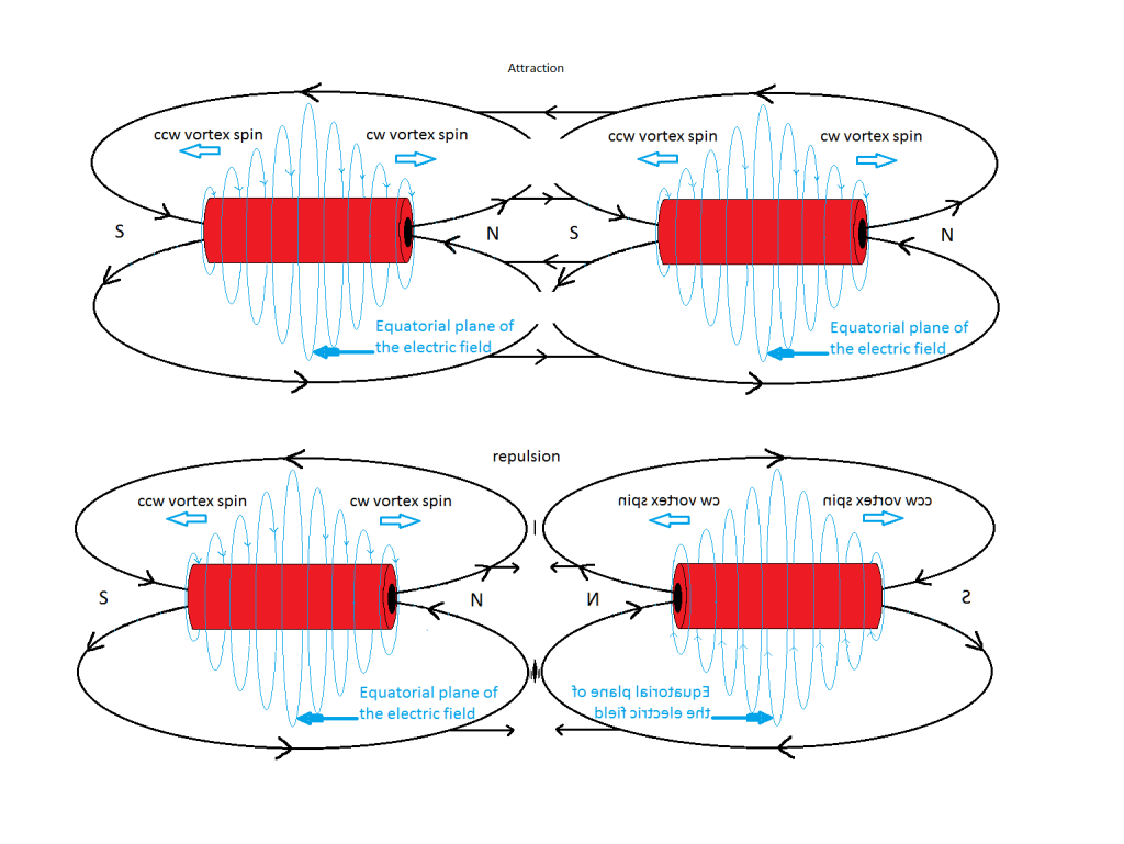
I know exactly what you are referring to...and I understand it quite well...but there is more to it..See we tend to dedicate more time to just "one event" when there are like other two going on at the same time...
For example : some people (must I will say) dedicate more time to electrical polarities, ignoring magnetic ones in a given Coil...
You have brought out a very interesting field, The Electric Field of a Magnet, and it is awesome!
I have figured out also what is going on inside the core of a Coil, right on the center, according to my experiments...I post it here a couple of pages back...
There is a center part that has been ignored by physics on any given Coil...an structure of opposed magnetic polarity that actually attaches 'internally' to the externally disposed one we all are familiar with...in every magnet or electromagnet in the world.

In my book you are also a great and respected experimenter Dave!!

Regards

Ufopolitics
Digg this Post!Add Post to del.icio.usBookmark Post in TechnoratiFurl this Post!Live Bookmark this Post!Google Bookmark this Post!Yahoo Bookmark this Post! share on MyspaceShare on FacebookTweet this thread
Reply With Quote
  #414 (permalink)  
Old 05-03-2012, 02:18 AM
cinan cinan is offline
Member
 
Join Date: Dec 2011
Posts: 58
Quote:
Originally Posted by Ufopolitics View Post
Hello Cinan!!

Ok, yes you are right about the right hand rule...I always check my coils with the tool I made (The Brass handle and coin shape PM rotating freely and centered) for polarity, ...so there are no mistakes.
My Coils range from 1 1/2 Inch (1.5) to 2 1/2 Inches OD.
In my latest video (Anti-gravity EM Effect) I used 200 Turns of Bifilar Parallel, no layers, straight all the way through end, and 18 gauge (awg) it gave aprox 1.4 Ohms resistance.
Now, the length on that one is like 2-3 Inches.
I will provide a pic of my coil in detail, later on (do not have them available right now)
I wind my coils in order to get both terminals above, opposed 180 degrees apart...I will definitively check them out again tonight and I will get back to you on it to-nite or tomorrow morning.
But, do not sweat that much over the winding...as long as you are clear where North-South are and have your terminals defined correctly.
I do not know what to tell you about the power supply Cinan, it sounds ok to me...and like I told you, I have not tried with a transformer, I will eventually, but am looking for the right Power Source, I want it Digital metered and ability to adjust Fine to Coarse output...
The Diodes must be super fast switchers, NTE 576 is also a short timed recovery spec's and goes up to 400 Volts and 150A peak forward current.
I tried cross referencing the number in your diode with NTE and nothing came up...I have here the other reference for the NTE576, is like UF505...search it.

I do also, want to move forward...I am developing a Motor and Generator of Radiant Energy that will get your socks down (not to say your panties... )...so get ready and fasten your seat belts...I will open another Forum for that Info...just to keep it separate and strictly to that field of Motors and Generators...
But I will moving forward to also open another forums in other sites like ATS and Overunity.com...even though I don't like them that much...but am looking to get over the 100 to 1000 million views...We need big time exposure for this to go world wide.

Cheers

Ufopolitics
Hallo Ufo,

very good. I will wait for details before I start winding... Regarding power supply. Once new coil and diodes will be collected, then I will test
this stuff together with battery and power supply too. To see difference. I just buy battery, no big deal. I will go fon NTE then, we knows its working with them.
It looks like you like rotating parts, do you ? Motor generator sounds very good to me, as I am involved quite heavily in diesel generator protection and control systems.
But I like solid state systems. And your discovery hopefuly can help to build one...

Ufo, before you start this big activity on other forums, please share here missing infos (you have said video nmbr.3) about how to boost her. Or only rough
sketch and info will do too. Lets cooperate on that. Based on that I will design some control system for that.

cheers,

Cinan
Digg this Post!Add Post to del.icio.usBookmark Post in TechnoratiFurl this Post!Live Bookmark this Post!Google Bookmark this Post!Yahoo Bookmark this Post! share on MyspaceShare on FacebookTweet this thread
Reply With Quote
  #415 (permalink)  
Old 05-03-2012, 02:19 AM
cinan cinan is offline
Member
 
Join Date: Dec 2011
Posts: 58
PICgen software

Dear all,

yesterday after whole day of hard work, firmware and software for PICgen was made. Its v1.0 and i am expecting some issues there, but we need to start with something. I will release it soon. If anybody is interested, jst let me know.

Cinan
Digg this Post!Add Post to del.icio.usBookmark Post in TechnoratiFurl this Post!Live Bookmark this Post!Google Bookmark this Post!Yahoo Bookmark this Post! share on MyspaceShare on FacebookTweet this thread
Reply With Quote
  #416 (permalink)  
Old 05-03-2012, 04:00 PM
prochiro prochiro is online now
Member
 
Join Date: Jun 2011
Posts: 56
I have been following this thread and will be watching for your progress.
Dana
Digg this Post!Add Post to del.icio.usBookmark Post in TechnoratiFurl this Post!Live Bookmark this Post!Google Bookmark this Post!Yahoo Bookmark this Post! share on MyspaceShare on FacebookTweet this thread
Reply With Quote
  #417 (permalink)  
Old 05-04-2012, 05:39 AM
Ufopolitics's Avatar
Ufopolitics Ufopolitics is offline
Senior Member
 
Join Date: Feb 2012
Location: US, Florida
Posts: 462
Coil Spec and fabrication

Quote:
Originally Posted by cinan View Post
Hallo Ufo,

very good. I will wait for details before I start winding... Regarding power supply. Once new coil and diodes will be collected, then I will test
this stuff together with battery and power supply too. To see difference. I just buy battery, no big deal. I will go fon NTE then, we knows its working with them.
It looks like you like rotating parts, do you ? Motor generator sounds very good to me, as I am involved quite heavily in diesel generator protection and control systems.
But I like solid state systems. And your discovery hopefuly can help to build one...

Ufo, before you start this big activity on other forums, please share here missing infos (you have said video nmbr.3) about how to boost her. Or only rough
sketch and info will do too. Lets cooperate on that. Based on that I will design some control system for that.

cheers,

Cinan
Hello Cinan,

Ok, here are the spec's of the latest Coil on my last video, that outputs power to five 120V/23 Watts CFL's, to my believe it is a good Coil for you to start winding...

Outer Diameter of Core =2.0 Inches
Height of coil= 2.0 Inches
200 Turns 18 awg wire (double strands), connected in parallel start with start, end with end.
After finishing winding the outer wire diameter gets very close to three inches.
The way I wound it:
1-I make my own spool ends or caps with fiberglass sheets, in a fiberglass tube that I also mold/make...now, this one was made over acrylic clear tubing just for video purposes...but I like fiberglass better since it can stand better the heat. (I use Polyester Resin with Methyl Ethyl Kethol (MEK) Hardener. The end caps prevents from wire to slip out of control and could result in a loose winding that will make too much noise and vibrations...
2-I start on top turning Clockwise and tight going down, at bottom start coming up, and so on...200 turns.
3-Now the Orientation, I really do not want to confuse you, but my start wire is my positive...and end is negative...still North is on Top, next to Positive (You've said is not possible, I will re-check this coil again..to make sure, maybe my compass is "shifted"...lol)...but like I told you before, this concepts of magnetic poles are relative for the purpose you are going to be testing, magnetic polarity does not matter, and you could test it with a compass or a defined polarity magnet.
4- Just define the positive above, at the starting wire, so install diodes according to that set-up.
I will prepare a set of pics and maybe a short video to show you my coil polarity and magnetic poles. However, on my latest video Coil, could be seen pretty well.

Ok, any more you need let me know

Sorry for the delay to respond.

Regards

Ufopolitics

P.D: I will keep posting here, I meant, I will also go on other sites Forums...
Definitively you will see video 3 here soon, I am kind of swamped with work...but eventually will make it pretty soon...and yes there are a lot of ideas I have in order to set controller for the secondaries to run-perform better.
So, I will be here

Last edited by Ufopolitics : 05-04-2012 at 05:47 AM.
Digg this Post!Add Post to del.icio.usBookmark Post in TechnoratiFurl this Post!Live Bookmark this Post!Google Bookmark this Post!Yahoo Bookmark this Post! share on MyspaceShare on FacebookTweet this thread
Reply With Quote
  #418 (permalink)  
Old 05-04-2012, 01:01 PM
cinan cinan is offline
Member
 
Join Date: Dec 2011
Posts: 58
Quote:
Originally Posted by Ufopolitics View Post
Hello Cinan,

Ok, here are the spec's of the latest Coil on my last video, that outputs power to five 120V/23 Watts CFL's, to my believe it is a good Coil for you to start winding...

Outer Diameter of Core =2.0 Inches
Height of coil= 2.0 Inches
200 Turns 18 awg wire (double strands), connected in parallel start with start, end with end.
After finishing winding the outer wire diameter gets very close to three inches.
The way I wound it:
1-I make my own spool ends or caps with fiberglass sheets, in a fiberglass tube that I also mold/make...now, this one was made over acrylic clear tubing just for video purposes...but I like fiberglass better since it can stand better the heat. (I use Polyester Resin with Methyl Ethyl Kethol (MEK) Hardener. The end caps prevents from wire to slip out of control and could result in a loose winding that will make too much noise and vibrations...
2-I start on top turning Clockwise and tight going down, at bottom start coming up, and so on...200 turns.
3-Now the Orientation, I really do not want to confuse you, but my start wire is my positive...and end is negative...still North is on Top, next to Positive (You've said is not possible, I will re-check this coil again..to make sure, maybe my compass is "shifted"...lol)...but like I told you before, this concepts of magnetic poles are relative for the purpose you are going to be testing, magnetic polarity does not matter, and you could test it with a compass or a defined polarity magnet.
4- Just define the positive above, at the starting wire, so install diodes according to that set-up.
I will prepare a set of pics and maybe a short video to show you my coil polarity and magnetic poles. However, on my latest video Coil, could be seen pretty well.

Ok, any more you need let me know

Sorry for the delay to respond.

Regards

Ufopolitics

P.D: I will keep posting here, I meant, I will also go on other sites Forums...
Definitively you will see video 3 here soon, I am kind of swamped with work...but eventually will make it pretty soon...and yes there are a lot of ideas I have in order to set controller for the secondaries to run-perform better. So, I will be here
Hallo Ufo,

thank you for info. Video 3 will be good to have. I still have problem to get Her. Your lamp flashes green during start, but my not... They go just flashes to white. I have to try NTE diodes, as they are last part different. Yesterday I've bought compass, so coil should be correct.

Last thing to ask for, can you send schematics of double power stage N-P you are using now ? Just configuration of diodes, coil and transistors is ok.

Once you'll sign up another web groups, let us know here, so we can follow too.

regards,

Cinan
Digg this Post!Add Post to del.icio.usBookmark Post in TechnoratiFurl this Post!Live Bookmark this Post!Google Bookmark this Post!Yahoo Bookmark this Post! share on MyspaceShare on FacebookTweet this thread
Reply With Quote
  #419 (permalink)  
Old 05-04-2012, 08:57 PM
Ufopolitics's Avatar
Ufopolitics Ufopolitics is offline
Senior Member
 
Join Date: Feb 2012
Location: US, Florida
Posts: 462
Hello Cinan

Quote:
Originally Posted by cinan View Post
Hallo Ufo,

thank you for info. Video 3 will be good to have. I still have problem to get Her. Your lamp flashes green during start, but my not... They go just flashes to white. I have to try NTE diodes, as they are last part different. Yesterday I've bought compass, so coil should be correct.

Last thing to ask for, can you send schematics of double power stage N-P you are using now ? Just configuration of diodes, coil and transistors is ok.

Once you'll sign up another web groups, let us know here, so we can follow too.

regards,

Cinan
Hello Cinan,

I am sorry that the Lady does not want to date you...
Just have to be patient man...women are like that sometimes...

Ok, the system should work perfectly well with just the N-Channel arrangement I have posted here...it does, trust me.
Now, I do not have a schematic of the actual dual channel, but I will load here where I got the idea from...A MOSFET Tester for P and N Channels below in pdf...
I used my same Old N-Channel circuit (I had made two of them) just added a second level small board just for second 555, 4.7 K and the 100 Ohms Resistors to 330 Ohms to gate of P-Channels and connectors for 555 ground and positive derived from same first 555...that's it...and of course added a bus bar to mount P Channels and respective connections of Source-Drain-Gates individually, I used a 4.7 K from Gates to Positive to Bias Gates...and it works fine, I know you would be able to make it just from this explanation, however I will try...not promising any soon- that I will make the diagram..and post it here.

Related to Diodes Coils and Transistors I have it...I will load it later...

Regards

Ufopolitics

Last edited by Ufopolitics : 05-22-2012 at 03:00 PM.
Digg this Post!Add Post to del.icio.usBookmark Post in TechnoratiFurl this Post!Live Bookmark this Post!Google Bookmark this Post!Yahoo Bookmark this Post! share on MyspaceShare on FacebookTweet this thread
Reply With Quote
  #420 (permalink)  
Old 05-04-2012, 09:18 PM
torpex's Avatar
torpex torpex is offline
Senior Member
 
Join Date: Mar 2008
Location: Spain
Posts: 99
Hi all

Quote:
Originally Posted by Ufopolitics View Post
Hey Torpex, I am glad you are making this replication, that is great!

Now, are you "slowly" dialing Up?...or are You rushing it as potentiometer turning means?
On this occasion did not touch the pot, was a rough shortcut.

Quote:
Originally Posted by Ufopolitics View Post
Purple light shows at low pulses...and is like playing on a thin ice for it to disappear on you, as you keep going up...
I'm still working with 12v,but I have decreased the frequency of the circuit (at 208 Hz) and I see the effect of purple neon light, also some white flashes (ball shaped).

This is my circuit:
L1.- 100 turns air-core 32 mm. OD
Q1 y Q2.- IRF822DFI
R4.- Adjusts the frequency. (less R increases freq.) Start at 30% of the pot
R7. - Sets the pulse width. (less R decreases the duty cicle) Start at
20% of the pot
C1.- 22nF (Frequency range 90-400 Hz)
C1.- 15nF (Frequency range 138-576 Hz)

Only Q1.- Not see the purple glow

I adapt the circuit to your specifications slowly . Thanks Ufopolitics for his explanations .

Attached Images
File Type: jpg UfoLowHz.jpg (88.3 KB, 102 views)
File Type: jpg 100_3149.JPG (303.0 KB, 36 views)
Digg this Post!Add Post to del.icio.usBookmark Post in TechnoratiFurl this Post!Live Bookmark this Post!Google Bookmark this Post!Yahoo Bookmark this Post! share on MyspaceShare on FacebookTweet this thread
Reply With Quote
Reply


Thread Tools

Posting Rules
You may not post new threads
You may not post replies
You may not post attachments
You may not edit your posts

vB code is On
Smilies are On
[IMG] code is On
HTML code is Off
Trackbacks are On
Pingbacks are On
Refbacks are On


All times are GMT. The time now is 11:11 PM.


Powered by vBulletin® Version 3.6.4
Copyright ©2000 - 2012, Jelsoft Enterprises Ltd.
Search Engine Optimization by vBSEO 3.0.0 RC8
2007 Copyright ? Energetic Forum? A Non Profit Corporation - All Rights Reserved