|
|
|||||||
| Homepage | Energetic Science Ministries | User CP | FAQ | Calendar | Search | New Posts | Mark Forums Read | Open Buddy List | Log Out |
| Renewable Energy Discussion on various alternative energy, renewable energy, & free energy technologies. Also any discussion about the environment, global warming, and other related topics are welcome here. |
 |
|
|
LinkBack | Thread Tools | Search this Thread |
Rating: 
|
 04-03-2012, 07:57 PM
|
||||
|
||||
|
Wow!!
Quote:
THAT WAS JUST AWESOME!! MANY THANKS!!! Mad Scientist!! Regards!! Ufopolitics           


|
|
04-03-2012, 08:12 PM
|
|||
|
|||
|
Quote:
When I originally designed this circuit it was meant to be use as a pulse width modulated signal for a motor speed control. As such I have used it with both P & N type fets and it has worked well. However there is no reason they cannot drive an opto-coupler. The chips output is an open collector transistor (emitter to ground) and able to carry 16 milliamp.
|
|
04-03-2012, 08:56 PM
|
||||
|
||||
|
Hello Mad Scientist
Quote:
Driving a motor on dual pulses instead of just one , normally an N Channel releases Radiant Energy at the Off Times, simultaneously on both ends...just that RE flows opposite, therefore wherever you had positive hot pulses, you will get negative radiant, and so negative hot will be carrying positive radiant... Two simple diodes blocking Hot, will deliver back a higher percentage of RE... Some say it is just "An Inductive Collector Circuit"...I have proven otherwise in previous videos...where it shows very clear there are Two Magnetic Fields there...opposite to each others, they both induce, one positively (Hot)...One Negative Induction (Cold Radiant)... 1-A "Motor Action" of a permanent magnet has been shown on video inside center of Coil... 2-An induced small coil has been illuminating "negatively connected" one and two LED's without ANY rotation of that small coil... 3-Now, I levitated a small magnet (UFO) with TWO LED's negatively connected to also a small coil fine wire and brightly lighting up... Is it still a "Single Collapsing Field Story"? Is still an "Inductive Collector Circuit"? The purpose of the Opto Isolator is to avoid MOSFET's to feedback HV to signaling low voltage circuit, in case they go bad and short out Low V circuit Gate with Drain or Source...that's all. I would like to send High Voltage Pulses to Coil with this square wave signaling. I appreciate your help here, my friend! Regards Ufopolitics Last edited by Ufopolitics : 04-03-2012 at 09:27 PM.
|
|
04-04-2012, 02:27 AM
|
|||
|
|||
|
hello ufo,
well ufo, you build the most amazing things, your grandkids must absolutely love you. Anyway, I liked your video. While I was watching it, I said to myself, that must be what hutchinson is doing. I never thought he really understood how his equipment worked, it always seemed hit and miss, but after watching your video, somehow his whole room became " inside the radiant field", or he must have a radiant beam., Does the radiant field draw in, only polarized materials, magnets, etc?, I would like to here your theory you must be developing. Definitly sheds light on Telsa's radiant energy beams and flying machines! Cool! Also, I'm trying to load a video of my setup you wanted to see, I hope it works, here's the link VIDEO0100.3gp - YouTube Thanks for sharing Thug
|
|
04-04-2012, 02:47 AM
|
||||
|
||||
|
Quote:
Thanks!...my little grand kids love this toys...  Well, this is not Anti-gravity for real, just an Electromagnetic Effect that defies our gravity...However , yes, it only works on magnetized objects... Actually, my main interest was to show there is a SECOND field in every coil...opposite to the one we pulse...to the point of Levitating a heavy and magnetically strong Neo magnet oriented exactly as our pulsed direction... The little UFO was for camera "show"...hehehe...but also oriented identical. If we do it the other way...the magnets will just shake but no levitation. Hutchison was playing with bigger toys...Higher Voltages and frequencies... Heavy duty Old equipment.. Yes He got the whole room into Antigravity...but the "Real One"...where non metallic or magnetic objects also levitate... Hey thanks for video!...that's good results and illumination!!... Did you run the motor yet? Regards Ufopolitics
|
|
04-04-2012, 03:38 AM
|
|||
|
|||
|
ufo,
Actually, i jumped while sliding the metal rod into the core. I forgot about magnetic effects and when the rod was pulled in i was looking at the amps.  Maybe hutchinson used two fields, one to polarize the object and one to move the object. I did hook up a small radioshack motor in parallel with the light and it worked very well, light dimmed, 1amp draw ran motor and light really well. I haven't had a chance to set up the drill motor yet, and I'm still trying to find a good cap size for timing circuit. In terms of wanting to use high voltage pulses, how high do you mean, greater then 20 kv? I used my circuit to run flybacks and car coils for my don smith set up, 10-20kv, and i know you can make car coils fire, + and - together, called anti-parallel, I've done that. Thug
|
|
04-05-2012, 10:38 PM
|
|||
|
|||
|
Hello
Hello guys,
I am new here. UFO, I read all your post, your website and watched your vids. Your dedication desreves tremendous respect, thank you very much for sharing.  Now I'm absolutely no expert in this field, while theory makes sense to me, I have no experience in electrical engineering. This is however so intersting that i will try to replicate anyway. I dont expect you guys to teach my electrical basics, so I try to ask you questions you can answer quickly, I would appreciate your help very much. 1. In the colorful drawing of the N channel, does the leg number 4 of the 555 end up in the potentiometer's 'A' (initial) ? 2. I will use the voltage regulator set up as of # 167 by kapierenundkopieren, OK? 3. Has anyone tried the IRF740 ( there was a post about it), I intend to use 3 of these as I can not buy the NTE2397 ? 4. Should I start with a Steel core coil ( 1mm wire 180turns primary + 180 turns secondary) or go straight to the air core ? And by the way did anyone try out the curcuit from kapieren's post #213?
|
|
04-05-2012, 10:51 PM
|
||||
|
||||
|
Hey Thug!!
Quote:
If you really want to "feel" the strength of that field...get two steel bars...and stick them one on each side...running towards the center core..Hold them tight...and once they get close enough you can feel the effect...the vibration...and then try to separate them...incredible force!! Hutchison used very High Frequencies, at HV , every object have its "resonant point" , but there are other frequency levels around any object that creates different outcomes...He says he was able to cold fuse many materials that normally require another parameters like high temp... No, not that high voltages...starting maybe at 100V to 4 to 600V... Related to Flayback Coils...they are fun...BUT...Did You know at that end of Positive, where spark comes out...there is also Radiant Negative? I have done that experiment and it is awesome...You have to use a HV Rectifier...blocking positive HV BUT, taking it (before diode to a Spark Gap...and also the terminal after diode (Radiant Negative) to the other end of spark gap...and if you have any Plasma Lamps...take a lead wire to each one separate (Two Plasma Lamp Bulbs...there you could watch both currents behavior...Sparky Hot and Smooth and Soft Radiant...Plus get near by Spark Gap or Plasma lamps any CFL or Neon..or Fluorescent bulb...it will lit up...And in the center coil core the intensity will be greater. Both currents will not spark (Positive Hot-Negative Radiant at HV) If You do not set them both in a Spark gap...you will damage the Flyback Secondary...it will burst. Regards Ufopolitics
|
|
04-05-2012, 11:17 PM
|
||||
|
||||
|
Thanks Alek, I am glad you've like them.
Quote:
Hello Alek, 1-Related to 'colorful' diagram I thought it was mine at post #97 (page 4)? The leg #4 of 555 is positive joined to leg#8, and it also goes to one side of Pot through a 1K Resistor... 2-The Volt Regulator from kapierenundkopieren, is supposed to be Ok, I have my own that I have used with the LM317... But if you have any kind of problems in Voltage Regulators....We have an expert here...Member Netica, will help you in that field...where she has got tons of experience. 3-Did you take the time to compare the Spec's (Data Sheet) of both transistors to find out any similarities or differences that could allow you to use it? Basically look at the Voltage rating Max Drain-Source, -+Gate Voltage, RdsOn resistance...and Amperage rating at "Pulsed" not continuous... If they are some how similar...they will be fine. 4-A Fixed Steel core will be safer...since you are starting, a solid one like the one on my pictures... Now you've said "secondary" ...we are talking about "Layers" of 180 turns connected in series first test...Ending Negative of first with Positive of second...so on.. Using just 180 turns of 18 awg (1 mm) wire as a Primary, will put too much stress on your oscillator...could damage your mosfet's. Originally, I mentioned (wrote here) three layers of 120 turns each...separated by masking tape...then I connected all in series...like I wrote above... Then separate one (120 turns) and use it as a secondary...but was oscillating 240 turn coil...not a 180... I have not tried any more oscillators...as of yet...but kapierenundkopieren, seems to be fine also...but there are better ones later on further pages... Good luck and keep us informed Thanks Ufopolitics
|
|
04-06-2012, 03:39 AM
|
|||
|
|||
|
hi folks,
well, I tried adding a 50k and 10 k pot in series to fine tune frequency, and i believe i ended up cooking my 555. I ordered some new ones last night, and while i was there i checked for diodes. These diodes seem really good, (600v, 10amps, 25ns!, reverse leakage current of 10ua@600v. I bought 20, I'm gonna make a 6000v, 10amp radiant filter for my don smith, as well as my ufo motor circuit  . the diodes were from digikey, part#RFU10TF6S-ND), . the diodes were from digikey, part#RFU10TF6S-ND), Ufo, people have been trying for so long with the don smith, I'm really hoping this can be used with that set up too, some how. I was gonna start with my new diode filter after my secondary. I'm trying to step down a flyback tranformer, with a resonant Don Smith set-up (L2 1/4 length and 4 times diameter of L1). I'm trying to use spark-gap and natural resonance, no caps on hot side of L1 primary, now i think the diodes may have to be reversed after L2 and run it/collect completely on radiant side (maybe use a dc motor for a load). Have you tried that type of high voltage setup before, or was your spark gap used in some other tesla coil setup, or something different all together? I would love to see a schematic of what your refering to earlier, when you mentioned the radiant energy and spark gaps. since my oscillator is fried i'm gonna start on the drill motor, and think about the spark gap. thug
|
|
04-11-2012, 02:46 AM
|
|||
|
|||
|
Hello, I'm new on this forum, and I were led here through my searchings of Nikola Tesla, and his Tesla Generator, since I'm searching for information, self teachings, and truth about the Alternative Renewable energy, and the conspiracies surrounding these important ideas.
Now I'm just rushing to a question with no prior knowledge or advanced electrical skills, and I only read half of the threads on this Topic, sorry.  But I saw your Anti Gravity Experiment, and noticed the alien aircraft recordings at the end. But here's my question: Is it correct to assume, that by using your demonstration in the opposite way, you could potentially have the recipe for creating a "UFO"? :-) I apologise if I'm completely wrong, or making it sound too simple, but bare with me. I'm still a 'Noob' 
|
|
04-11-2012, 08:17 PM
|
||||
|
||||
|
Anti-Gravity...
Quote:
Hello Thane, I read You have researched Nikola Tesla...so there may be a chance you have glanced at his Extra Terrestrial side...and also to His Anti-gravity development. If You also read and see video demonstrations from John Hutchison, will also find a lot of info there related to UFO's, Anti-gravity and Electromagnetic Fields.. And related to my latest video...that is not the "Real" Anti-Gravity manifestation as it is conceived by our sciences...but an 'Effect' of Electromagnetic Field that develops into a levitation of magnetic materials... Anti-Gravity develops in ANY object, no matter its composition, however electromagnetic fields are very closely related to anti gravity. The UFO at the end images are from the Jerusalem UFO on Jan 2011...there were many different angles views from different points...they say it was a big movie to be produced...coming soon to a theater near you...it never happened. And I, particularly believe it was a completely real event. Milliseconds before the UFO departed in a speed beyond our technical development, it flashed a couple of times...All witnesses videos (synchronized) show exact same timings on the strobes and vertical take off... I have been working on Radiant Energy for quite a while...and it may be 'pure coincidence' that the Anti-Gravity effect only comes up, stronger, at very high peaks of Load output...which I use Lights... That's the reason why I showed those clips there... I leave it to the mind of the viewer to judge according to his knowledge... P.D: I have no idea if that would be a 'recipe' to make a UFO...  Thanks for your comment. Cheers Ufopolitics
|
|
04-12-2012, 07:50 AM
|
||||
|
||||
|
Hi all
@Ufopolitics Thanks for sharing your experiences, are very interesting. I've been playing with Alexkor chargers circuits (Frequency in Alexkor charger) I have read all pages of this post. I put the second diode on the coil and noticed a voltage reading that I find it curious. Multimeter in 1000v DC-Hv, no load in output coil. Probe + in cathode of the collector diode. Probe - in cathode of the 2º diode (coil to positive bat) = 396v Probe - in anode of the 2º diode (coil to positive bat) = 401v Adjusting the pulse width changes the output voltage reaching 500v. Over the range tested observed the same difference of 4-5 volts. My next step is to replicate Ufopolitics first experiment. I hope not to bore you with the doubts.   Last edited by torpex : 04-12-2012 at 03:40 PM. Reason: image added
|
|
04-16-2012, 12:43 AM
|
|||
|
|||
|
ufopolitics have you tried two toroid magnets inside the coil in opposition mode, will it expel one or hold both inside?
DEFINING RE FIELD (Part II) EM ANTIGRAVITY EFFECT - YouTube
__________________
Half of the Answer is knowing the right Question
|
|
04-16-2012, 04:54 PM
|
||||
|
||||
|
Hi all
Playing with Alexkor-Ufopolitics circuit: The neon lights very bright but does not become purple. Connecting the output through the neon into the positive and parallel to the second diode, sometimes starts to oscillate otherwise and reaches the purple. Give some peaks in ammeter input, but then stabilizes.
|
|
04-16-2012, 07:02 PM
|
||||
|
||||
|
Magnetic Fields
Quote:
No, I have not tried two toroid magnets in opposition, however, let me explain the behavior so you could judge what will happen when you do... The Coil is oriented by Hot pulses to be North Top, South Bottom, which is equal to: [N/S]. Now the Magnet that I put in must be oriented same as Hot Pulsed Field, or [N/S] in order to be ascended and staying into levitation. If I put it the other way around, or [S/N] it will just vibrate but no levitation, will stay in the floor... Therefore (and answering your question)...The magnet (toroid) that would be opposing to right oriented one will not ascend, nor levitate, just vibrate...if they would be attracted to each other configuring one magnet , with same orientation...it will suck them both in, and levitate them. To understand this behavior we must analyze the Radiant Magnetic Field, opposing the Hot pulsed field, or same as [S/N]. Hot Field=[N/S] Radiant Field=[S/N] However, Radiant Field is located right at very center of Hot, which looks like: N(Hot)/S(Radiant)/N(Radiant)/S(Hot) That configures the positioning of the Chain of magnetic links on this Coil. The magnet oriented N/S will levitate because of Radiant EM Field being stronger than Hot EM Field...Radiant S (on top center) will attract N of levitating magnet, while N Radiant (on bottom-center), will attract S of magnet...However, Hot field will 'compensate' the magnetic fields on the floating magnet by establishing a N/S repulsion at the upper-lower extremes... That is what I understand so far, related to this phenomena. I hope it helped your question. Regards Ufopolitics
|
|
04-16-2012, 07:05 PM
|
||||
|
||||
|
Hello Torpex!
Quote:
Hey Torpex, I am glad you are making this replication, that is great! Now, are you "slowly" dialing Up?...or are You rushing it as potentiometer turning means? Purple light shows at low pulses...and is like playing on a thin ice for it to disappear on you, as you keep going up... Let me know. Thanks and cheers Ufopolitics
|
|
04-16-2012, 10:00 PM
|
||||
|
||||
|
RE-HOT MaGNETIC FIELDS DISPOSITION
Hello to All,
Here is a better schematic that describes the proper orientation of the Radiant Energy Magnetic Field Poles and the Hot Poles (Our pulsed Field) in relation to each others in a given Coil. The rectangle in center is the levitating permanent magnet on my video. As I explained to Dave45 prior, this is the arrangement I believe is been developed when we pulse a magnetic field into a Coil, and the way R.E. responds. The magnet is attracted towards center of coil (where R.E Field Poles are) based on a double attraction [S>N/S<N][ from R.E. Hot magnetic field creates a 'double repulsion' towards the permanent magnet, that assist to keep it floating. Permanent Magnet will NOT levitate if positioned as [S/N], related to N/S of Hot Field. Therefore the Attraction from Hot is weaker than Radiant Field. If We set a Flywheel Diode on the Input...The magnet will fall...the lamps will turn off...Radiant Field will crash, and the Radiant electrical flow will loop within coil... Regards Ufopolitics Last edited by Ufopolitics : 05-22-2012 at 03:21 PM.
|
|
04-18-2012, 11:29 PM
|
||||
|
||||
|
Quote to Myself...
Quote:
Quote:
This methods of Fly-wheeling Diodes, Chokes and Snubber Circuits have been The Electrical-Electronic Engineering best 'shot' so far, to wrongfully "trying" to keep Radiant Energy trapped... Regards Ufopolitics
|
|
04-25-2012, 08:26 PM
|
|||
|
|||
|
Hallo Ufo and others,
I am new in this interesting thread. I saw some of your videos on ytube and it attract my attention. Then I went through discussion on fcuk book and finally landed here ) BecauseI wanted to know what was/is happening here, I've red all messages since beggining and must say it was fun. Your first introduction post was self explanatory and pretty clear. It was obvious that you know what u r doing and what r u talking about. And then again (as on other threads in energetics forum) some smart asses start jumping shouting crap and making stories and theory. Then I came across red,bold letters.... Those strict rules made by you are gud idea and I love that approach. By the wayt, you are very patient, coz I would stop responding.... But back to the topic. I want to participate in this as much as I can. I have good electical and electronics background, and experience in electronics design. I will help you to develop all driver and other circuits. I also have theoretical info about topic, as I've read a lot of Tesla's, Vassilatos, Bearden's, Lindeman's, etc books... After reading of whole thread is almost all very clear and based on that I've made some circuit modifications this evening as I have some spare time now. Details in next post. BR Cinan
|
|
04-25-2012, 08:29 PM
|
|||
|
|||
|
Improoved MOSFET driver
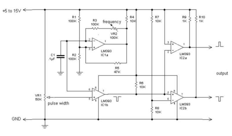
Driving MOSFET properly is not so easy. Each MOSTET needs certain driving current, which is dependent
on gate chagre (Qg) and frequency and demand on driving circuit is increasing wif frequency. Higher frequency, bigger driving current is needed to "fight" gate capacity. Proper current will ensure steep raising edge of impulse, and this is what we need. This boosting is specially needed when MOSFETs are paralelling, as total gate capacity is Qg1 + Qg2 + ..Qgn. So goal is to choose MOSFET with low Qg and low Rds as silicon power disipation is dependent on current and Rds. In att. you have oscillator circuit posted before by Mad Scientisct with corrected error in wiring and booster stage for MOSFET. This solution is low side, single phase only. For tests you can basically use any generator and boost his output via any MOSFET driver. In this case MCP1406 from Microchip. See datasheet for connection details. There are other low side driver circuits (inverting/non inverting) on the market and yu just need to pick proper one. See Farnell or Digikey for additional info. MCP1406 / IR4426 / TC4427 / etc... Cinan
|
|
04-25-2012, 08:30 PM
|
|||
|
|||
|
Filter on cold side
Somebody down in thread mention, that electrolytics cap will explode or over heat when connected
to diode output. Yes, thats obvious as elcap is not made to handle HF/HV currents!!! There few solutions of this problem. One is interlaced configuration of coil "pump". 180 degree shift with one common output. This solution will lower ripple current half. Another solution is to make double filter stage. First stage will be equiped with film capacitor. This one can handle HF currents. Second stage will be ordinary elcap. See att for drawings. But there is one think. Once you connect capacitors on cold out, energy will change from cold to hot again. Ufo can you confirm that fact ? So if you want to run motor cold, You can't connect caps on output ! In this case interlaced coil config would be sufficient. http://uk.farnell.com/illinois-capac...ial/dp/9681175 http://uk.farnell.com/panasonic/eeth...0uf/dp/1973452 Cinan
|
|
04-25-2012, 08:32 PM
|
|||
|
|||
|
Coil Driver circuit
And my last post today is suggestion for precise driver circuit based on ICL8035 and his equivalents.
You can adjust freq, duty cycle, and other parameters as will. Output is SINE / TRIANGLE / PULSE. In this case I am only using PULSE output. But you can also use SINE and TRIANGLE outputs for other purposes. See google for connection pictures. Output signal is boosted via MOSFET driver and connected to tranzistor. Coil connection is also highlighted. Picture is in att. http://ww1.microchip.com/downloads/e...Doc/22019a.pdf ICL8038 - Precision Waveform Generator/Voltage Precision Waveform Generator/Voltage ICL8038 [ICM003] - $5.00 : iStore, Make Innovation Easier NTE864 NTE NTE Replacement Semiconductors Cinan
|
|
04-26-2012, 07:43 AM
|
|||
|
|||
|
Double switch driver circuit
Hallo all again. If I remember goog, Ufo was talking about two switches out of phase for driving.
As input signal is out of phase, I assume that two switches in P-N configuration are used. P for top switch and N for bottom switch. Ufo please confirm. If this is the case, then I propose configuration only with N-MOSFET involved. Driving P-MOSFET and get good performance is pain in ass. In schematics you have HI /LO driver circuit with only ONE pulse input signal. Power supply for coil is separate and can be up to 500VDC !!! Then we can use monster BEMF. Input signal amplitude CAN NOT be higher than chip power supply value. I suggest 5...10V pulse amplitude for driving input. Performance of circuit is superb. Ton/Toff below 150ns, frequency up to 25kHz with proper Q1/Q2 To achieve higher frequency range (if necessary) we need to change driver IC as IR2101 has only around 250mA and for higher frequency we need bigger pulse current as explained in my previous post. But so far we are operating up to 10kHz, so circuit is designed for that. Ufo please comment it. cheers Cinan
|
|
04-26-2012, 11:02 PM
|
||||
|
||||
|
Hello Cinan!!
Is GREAT to have you here Cinan!!
I can feel you are charged up to max  , that's very good! , that's very good!Ok, I will start answering some of your doubts... 1- Quote:
They are not"out of phase", but in Anti-Phase, they are completely aligned at their T-On/T-Off's, but they are one low one high to drive Mosfet's Gates accordingly. I have not worked on making a "Dead Time" between them as of yet... This is in order to achieve a simultaneous Dual Pumping of Positive and Negative, at same exact times On, leaving a "Room" for Radiant to flow back at the T-Off times, understanding that T-Off=T2-T1... I know this could be done with only N-Channels, making it more robust an easier to drive...Give it a try Cinan and share results. However in my previous work I had just an N-Channel oscillator and it also worked out fine...not as successful as dual outputs though... I also understand using Mosfet's Drivers will enhance the switching performance. Now, what we are using is a Square Wave, NOT a Triangle or a Sine wave. It is very important to understand that Radiant enters at the T-Off times ONLY. Triangle Waves have a T-Off mixed with a "Non Zero" Drop down of Hot...THAT'S NOT GOOD!! Sine Waves also, does NOT have radical, Zero Time drop Off, in order to create a better Radiant entry either... OK, Next issue: Quote:
Getting in the 10KHz is also great, BUT REMEMBER, We MUST start the Invoking of Radiant at LOW FREQUENCIES, and as we climb Up, She will do it also... Radiant will NEVER enter if we start at High Frequencies, that is a LAW for Her. I have tried, already made Motor Controllers, from small R/C to heavy duty 48-72 Volts... and they simply does not work out, Why?...'Cause they ALL are designed to start at a given Frequency, like 800-1000 Hertz to stand the Motor Torque and BEMF...NOT GOOD!! She starts Thriving (showing up pulsing at your monitoring lamps) at 300-600 Hz...but coming from lower Hz...like 100-300... To be Continued next...
|
|
04-26-2012, 11:47 PM
|
||||
|
||||
|
Cinan Response Part 2
Quote:
Yes, ElCaps will blow on Radiant, at least if they have a safety valve will just make a noise, a pretty loud BAM...and like you have said, a film cap will do a first stage and then Electro's will store it... Yes it will return Cold to Hot, so you are right about driving a regular brushed motor will be better using just cold. But when using it to drive other hot equipment, then it needs to be converted, or, it will blow their Caps at the Input Power Source...what a shame Ah? Tesla played, designed and patented Oil based Caps...for HF Currents. Second Part: In another mail you sent, you asked me how to get Output magnified... When you do your first testing, will notice your output (after diodes) is pretty amplified...measure Amps and Voltages at output please. Now, there are other ways to amplify Radiant, One is through secondaries of finer wire and more turns, without allowing Hot Induction to Thrive at Secondary Coil Cores... I have a video coming soon ( Part 3 of Defining RE Field) where I show two ways of inserting secondaries and obtaining HV Output in the two magnetic field planes (Horizontal and Vertical ) relative to Primary Coil. The best results I have achieved so far on primary coils are based on a Bifilar Coil of 18-20 gauge at low ohms (1-2) around 200-300 turns. But in PARALLEL not in series like in Tesla's Patent, it will not work in series one wire with other... Now, the currents coming out of a Higher Turns (4000-8000) on 33 gauge Secondary are very strong, much stronger than the ones coming out of the primary after diodes. They will really shock you, not burnt you, but will be very High Impact...This currents will create a Plasma Arc in a Xenon-400Volts Min/ Max 1000V, Radio Shack Bulb with no filament (look like a U upside down) It will also create a heavy Arc in a High Discharge Sodium HID Bulb of 120V/50 Watts or more... And they will also open a big hole in your meter circuit board if you try to measure them...It did it on one of my Extech's, a hole from one side to other...a HV arc, I suppose inside, is the only thing I believe could do that...while meter was showing O.L. (Overload). Regards and I hope I had covered must of your questions doubts. Cheers Ufopolitics
|
|
04-28-2012, 05:47 AM
|
|||
|
|||
|
Hallo Ufo,
thank you for answers. I had some spare time again yesterday, so I've designed custom made 2 chanell generator. By this subject will be covered in next topic. Now back to your response. Can you send me rough sketch of two 555 oscillator and power stage you have made ? I just want to confirm sommections. I also wrongly expressed myself regarding 'out of phase'. Yes, correct term is antiphase, this is what I ment.... Yes, square wave is only shape good for driving. All MOSFET drivers can work only with square wave. And as per Tesla's research, radiant energy appears only on edges of that square pulses.... Frequency sweep from low ho higher to invoke this lady is very good note. I didn't know that. What is max. frequency for biggest radiant harvest ? Its dependent on coil design of course and there should be one point, I assume. Is that right ? Or multiple points (as there ara harmonics), but one should be max.peak. I will do tests once generator and coil will be built. Regarding magnified output. hehehe, I can imagine how did your face looks when one of your eyes was looking through hole in instrument. It happened to me once, when I was young and doing some 'research'. Secondary coil with more turns its clear, but how to avoid hot induction there ? Loose primary coupling ? Connection ? BR Cinan
|
|
04-28-2012, 05:49 AM
|
|||
|
|||
|
Custom made generator
Hallo all,
as everybody is looking to build some generator, I made design for PC controlled custom made one. Its has variable frequency from 30Hz to 25kHz, variable duty cycle 1 - 99% and two galvanically isolated outputs. Its based on PIC18 micro controller with USB connection to PC. Control SW has graphics interface. Snapshot is in att. It has few useful features, like frequency range setting, frequency sweep, duty cycle sweep, preset output buttons, etc. Its still under development. If is anybody interested in that, please let me know and I will give you details. Future development is flexible and any routine or function will be added if necessary. For schematics, see att. There is simple version of HW. The advanced one has buttons for Freq and Dc control, DC/DC isolation converter for outputs, some LED, etc. I can publish it later on also. Programming is veeery simple, and tool is for 30USD from Digikey, SW is for free. Total cost of simple version will be roughly - programming tool + 15USD parts... BR Cinan
|
|
04-28-2012, 02:01 PM
|
|||
|
|||
|
Quote:
You are of very good help here, indeed. I plan to build a big coil to try replicating ufopolitics's discovery. aaron5120
|
|
| Currently Active Users Viewing This Thread: 9 (4 members and 5 guests) | |
| lamare, cinan, hdtbiz, prochiro |
| Thread Tools | Search this Thread |
| Rate This Thread | |
|
|