
 |
|
|||||||
| Homepage | Energetic Science Ministries | User CP | FAQ | Calendar | Search | New Posts | Mark Forums Read | Open Buddy List | Log Out |
| Renewable Energy Discussion on various alternative energy, renewable energy, & free energy technologies. Also any discussion about the environment, global warming, and other related topics are welcome here. |
 |
|
|
LinkBack | Thread Tools | Search this Thread |
Rating: 
|
 05-21-2012, 04:33 PM
|
||||
|
||||
|
Hello ZPE!!
Quote:
Hello ZPE, Quote:
 I really love the innovations...or to get "The Best" out of the whole thread, like Bob did...and make it happen!! I am still using the old 555 timer...I have bought the (2) LM393...and also the LM339...I have all components but...have not found time yet, and I know it is much better than the one I have... I have been working hard on the Motor set-up lately...and in the videos...they both take more than my extra time...plus writing-reading here...lol The 555 have the inconvenience I can only accelerate up to a point...after that it turns almost linear...not good!...I can not adjust duty cycle either...so I must make the LM set up...I want to build two, one with several N-Channels and just one Drain out...and the other one usin Cinan's double N-Channels to obtain dual anti-phase channel drains on Positive-Negative...However I am going to wait for that till Cinan burns some Mosfet's first... Now, You DO have studied that purple light very close, don't you?!...It seems you are trying to "Glorify that light"!!??... Be careful, my friend!!...someone could come over and accuse You on "glorifying" that purple light!! HA HA HA HA...LOL Regards my friend!! Ufopolitics           


|
|
05-21-2012, 07:44 PM
|
|||
|
|||
|
Anti-Phase
Quote:
Thank you for your electronics knowledge and expertise. I am fairly ignorant of these things, so your circuits and suggestions are very valuable to me. You and MadScientist have made this possible for me. Thank you. This circuit is so small on my screen and when I blow it up it gets blurry. How can I view it better? It looks like the next logical step. I can' t make out the components and there appears to be 6 wires going in and out. I guess that would be 2 for power in, 2 for output (w/ an end of the coil), 1 for timing, and 1 for one end of the coil. (?, just guessing?) Perhaps it would work for me if you posted it on Photobucket. (?) If you could help me get a clear copy I would be grateful. UFO, Nice looking rotor. Can't wait to start into the motors (hopefully with CF windings!!!). How does the copper wire directly to the acid in a battery work? What drives charges to the plates if their not in series with the system, but just beside it all, just touching the electrolyte but not having the charge directed in and out through them? What is going on there? If this works I will convert my 36v banks and run tests. Let me know if it works. Thanks. Hey, UFO, what city are you in? Are you up near GA or AL, or down toward Cuba? I may consider running down to visit you sometime (and bring my stuff to show and try). I may have CF coil built this coming weekend.http://www.energeticforum.com/images/smilies/dance.gif UFO, Is there any reason for me to not build the Anti-Phase unit? It seems like that would be the next step. (?) Add a CF coil and make plans for space travel! HEE HEE. OK. Back to it. Bob
|
|
05-21-2012, 08:06 PM
|
|||
|
|||
|
Lm339
Quote:
I found the LM339 to be easier to use as everything comes off of one side except one wire (pin 12). This made it very compact. I posted the hand draw circuit at: Pictures by bobfrench - Photobucket Dana has converted it to a PCB form and is going to make a home made circuit board of it. Another friend, Luther, has a friend that is very good at that and will convert it also. I hope that it will not be so convoluted that I can't understand the wiring. My hand drawn circuit is clear and easy enough to follow. In updating it I made a cap smaller in order to get higher frequency. I tested that and it works. My better charging was above 2000Hz. I also replaced a 100k ohm fixed resistor with a 100k pot so I could get lower frequency. I've actually placed a third 100k pot in series with the other two now. My duty cycle seems to be around 40% in order to run it at 1.2A which seems to be good. More amps does raise charging, but goes past the C20 discharge rate for the Primary. (so does the 1.2A, but...) Once you build this controller you will love it. I would advise that you make it separate from the MOSFET heat sink so that you can attach it with small bolts and be able to transfer it to other setups easily. Also attach the coil ends with 3.5 phone jacks so trying different coils is easy, too. Easy makes it so much more enjoyable. When an idea pops into your head it's a drag to think...oh, well, now I've got to unsolder this, solder that on...and so on. If you can just slip things together, you will just do it, change it, do something else...all in one session. Take care and thank you for your kind words, Bob
|
|
05-21-2012, 08:31 PM
|
|||
|
|||
|
PM
UFO,
Would you e-mail me at: bobfrench@fastmail.fm I would like to send you a private message. Thanks, Bob
|
|
05-21-2012, 08:58 PM
|
||||
|
||||
|
Hid Bulb Lighting With Re Video
|
|
05-21-2012, 11:20 PM
|
|||
|
|||
|
Quote:
Hallo Bob, sorry for pic. I didn't open it to see in www. Here is pdf file. Now I have to run yo aport. Have a fun here. Cinan
|
|
05-22-2012, 01:24 AM
|
|||
|
|||
|
At Last
G'Day UFO
I have now at last read all the posts here. I wanted to do so before I started to build and I just could not wait to order parts So I did so as soon as I was able to see what was needed First I would like to thank you for starting this thread  I Actually discovered this site when Bob French and Dana on BM2 were discussing what they were learning from you and am very glad to be here  I am not an EE I am a simple Joiner(Wood worker)retired but for the last 5 years or so I have been looking for a way I could build an electric motor to drive a car But every forum I have joined (Including this one) has had NAYSAYERS or as I would call them trouble makers that seem to try to direct others away from what is being shown to them and therefore the ones taking the lead have spat the dummy so to speak, and have lost interest in continuing to show what they know I am really glad that you perservered and stayed on this site  I appreciate all those on this thread with knowledge expanding on what they have learned from you and helped others like myself to be able to understand these things.  Now that I have read all the posts up to date I already have purchased the components to start to build as you have described. I will be building with the 555 timer first as I have purchased those parts. When I finish building I will show what I have built and of course will be able to show all my friends who think of me a MAD SCIENTIST(I mean no disrespect to Mad scientist here ) One of my friends about 5 years ago said to me How am I going to do these things when I did not know even how to use a multimeter I am truly glad to be here All my friends call me Kogs Kindest Regards To you and all others here Kogs
|
|
05-22-2012, 04:16 AM
|
||||
|
||||
|
Hi Torpex
I have a quick question, but first congratulations on your test. Now did you measure the voltage drop across the leads of the eco bulbs or are you stating they are rated at 240V 15W and so on and look to be bright? Measuring the voltage drop across the leads will tell you for sure if you are at 15W or what ever watts bulb is rated at. If you have 240V across the leads you will have the watts that the bulb is rated except that I have read that the CFL bulbs actually draw twice what they're rated watts are. So you might be doing better than you think. Thanks for your report. Thanks Larry Quote:
|
|
05-22-2012, 12:48 PM
|
||||
|
||||
|
Thank You
Quote:
Hello Iankoglin, Thanks for your kind words, you have no idea how they rejoice my soul... Must of times we do not realize how valuable our words as an expression of our feelings could be...but I do perceive them clearly when they come full of joy and positive feelings... You will be able to build that motor for your vehicle very soon, and more... The circuit with the timer 555 is pretty good, I have driven big motors with it...is a simple system to start playing with. To a certain point it is good not to be an EE, during all the career you learn all possibilities not to obtain results that violate certain laws, that fact becomes a barrier to understand anything that brakes those rules...it ends up blinding and narrowing your points of view, unless you were the type who always wanted to go beyond whatever they thought you, and argued with your professors to exhaustion about other methods and possibilities... I wish you the bests of luck in your project, and We all will be here to help you in case there would be any problems in the way to the light. You have great guys there, Bob and Dana...to guide you through this. Warm Regards Kogs!! Ufopolitics
|
|
05-22-2012, 01:00 PM
|
|||
|
|||
|
Ufo I hope you dont mind, I used your pic
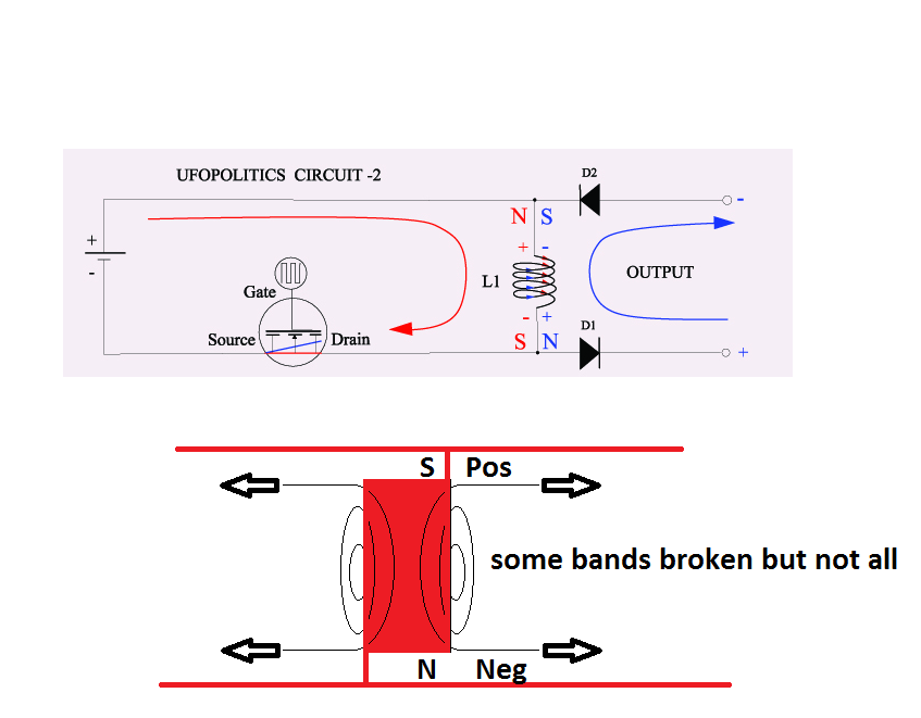 How can we access this field Add coil whisker's 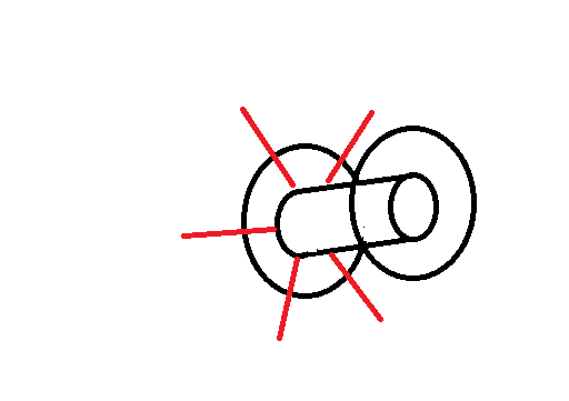 Im not sure yet how the connections should be, but we can access these fields, there is a field on both ends of the coil. @Ufo some idea's you may give a shot, easy to implement
__________________
Half of the Answer is knowing the right Question
|
|
05-22-2012, 03:27 PM
|
||||
|
||||
|
Hello Dave
Quote:
No, I do not mind that you use my picture, by all means it is my pleasure. I will give you my input... Ok, the fields at the end of every coil, relating to Electromagnetic Fields, and not the Electrical Fields, are the ones We generate whether linear or pulsed by our Input...They are the Hot current generated Fields manifested at the extremes of the coil. However, this fields are "flexible", and very Dynamic, and according to the spec's of our input and also to the Coil design will generate many different patterns. As long as we keep the loop between our pulses and the coil, at specific times open...it will generate a Magnetic Resonance of greater magnitude in the opposite direction, that "Reaction" is born, starts, right at the center of every coil, and dynamically expands in 'exactly' two planes, one parallel to the coil axis, and we could say it is not exactly a 'plane' but a 3D cylindrical geometry that expands towards the upper-lower extremes of coil, the secondary plane is perpendicular to the coil axis...and it grows towards the outside (exterior) space of coil. I know this because I have designed secondary isolated coils sandwiched between a segmented primary...and also inserting a vertical (parallel to coil axis) second coil...Both Induce "Negatively", opposite to "Positive Induction", since I did not grant at all any possibility for Hot flux to Induce in this secondaries... However, the vertical coil induces faster than horizontal one... Below is the Pic of the Model Coil I have built...with two secondaries (I am making a video of this) I have take it apart to show it in an exploded view...note the inner coil and the center (sandwiched) between a segmented in two Primary. The vertical secondary has 8000 turns of 33 awg The Horizontal 4000 T/33awg Primary has 150T Bifilar in each segment of 18awg The primary Space frame has two parts with four fins on upper-lower. The center Steel Ring is isolated (physically) from main frame and it enhances the horizontal field. The upper and lower steel fins attach through a brass bolt (non magnetic material) to a center steel bar (not seen, inside) that enhances the vertical secondary resonance. The Steel Space frame serves as magnetic enhancers as they also provide heat sinking. The other pic is showing the Coil lighting two 400 V Xenon's Strobe Bulbs (no filament bulbs, just Xenon Gas and two electrodes, they create a High Pressure Discharge Plasma Arc. Primary is illuminating the 23 W CFL through Radiant output... Later I will post the preview of this coming video. Regards Ufopolitics
|
|
05-22-2012, 07:16 PM
|
||||
|
||||
|
Alien Coil Video
ALIEN COIL PREVIEW - YouTube
Quote:
Last edited by Ufopolitics : 05-22-2012 at 07:18 PM.
|
|
05-22-2012, 11:15 PM
|
||||
|
||||
|
Quote:
How big is the biggest motor you have run with this and do you have a video of it? Also I am ready to build the PWM/frequency part of this and I am not sure which I should build. The first thing that was presented is the PWM circuit, but then you talked about the importance of getting the frequency and the PWM right which leads me to believe I should build a driver that the frequency and the PWM can be adjusted Independently. To my knowledge there isn't a good circuit built with a 555 that will do this. I would prefer to have one that will do very fine tuning. Then you started to talk about both positive and negative square waves. Not sure what to do at this point. My goal for this project is to use it to power my electrolysis system and to power a 100hp electric motor. You have stated that it should be a brushed type motor... I was wondering what is the problem using it to power a brushless motor? Too many questions in one post sorry. One more question... on the hot side when you transform a lower voltage to a higher voltage you reduce the available current by the same proportion. Is it the case of RE? With what I am going to do, I need big current too. Regards Larry Last edited by larryross : 05-22-2012 at 11:28 PM.
|
|
05-22-2012, 11:31 PM
|
|||
|
|||
|
Hi Larry,
The most "controlable" setup would have to be a STAMP or PIC or I've purchased an ARDUINO. These microprocessors make it simple to control both dutycycle and pulsewidth. They are also inexpensive - mine A$39.00 Simply connect output pins to transistor switch or mosfet controllers. Regards, Penno
|
|
05-22-2012, 11:52 PM
|
|||||
|
|||||
|
Good questions
Quote:
Yes too many!!... But is Ok...I will number them... Quote:
Quote:
The LM339 is a Dual Op Amp based on two LM393's...this circuit could be expanded or "Upgraded" to make it Dual Anti-Phase also, meaning, pulsing Positive and Negative Channels simultaneously. And Frequency and Duty Cycle can be adjusted separate. Hope this cleared your doubts..  Quote:
However, I recommend that you start from a lower level test first, measuring the Capacity of Outputs and running your calculations to scale it up... Quote:
Of course I am not talking about the smaller BLDC like the ones used in PC Fans...those you will blow the small electronic circuit that contains small hall sensors and NPN little transistors as soon as you connect them to Radiant High Frequency current... I recommend the brushed motor, simply because I know it works great, without major complications...and they do, can stand Radiant. Phew, Larry...You got me to work!!... is good I know all this by "ear" and do not have to start "Googling" it... Is ok...love to be able to respond to you my friend, and hope I did ok Regards Ufopolitics
|
|
05-22-2012, 11:55 PM
|
||||
|
||||
|
Arduino...
Quote:
Welcome! Just one question...what kind of Arduino circuit?...the Motor Controller? Did you try it with my set-up? Thanks in advance and for answering to Larry! Regards Ufopolitics PD: I have tried oscillator-controllers from small R/C Motor controllers...however they do not work...they do not come down to very low Hertz...to start dialing up...they seem to be designed to start at 800-1000 Hertz...to stand the Brush DC Impact at start. not good for this set-up. I have also tried heavy duty controllers for Electric vehicles...they have not worked out for me...same thing but at bigger scale, they are designed to stand the Big Spikes of Brushed Motors...therefore spend battery like crazy..they have a huge capacitor bank (@ 8- 10 1000mfd in parallel). so filling that up...in the On-Off tests will kill batteries very fast. Last edited by Ufopolitics : 05-23-2012 at 12:06 AM.
|
|
05-23-2012, 12:10 AM
|
||||
|
||||
|
Hi @ZeropointEnergy,
Quote:
In my current circuit, I can regulate frequency and pulse width, but I have observed anomalies, what did you mean that? What is your current circuit? You already have the parts to assemble the new circuit? Where are you from? On the other hand I've been playing directly with a frequency generator, the results are the same. Light bulbs with energy cost but similar. My FG drops to only 10% duty cycle. The best performance I have it on 5.6 kHz and 42 kHz. I think something is wrong The new video I've seen it but I need to see it easier, not easy for me to understand because the difficulty of the language.  
|
|
05-23-2012, 12:32 AM
|
||||
|
||||
|
Hello Kogs, welcome to this thread
 Quote:
Yes, I measured across the legs. My reference is 250v DC. To test I use 3 references (with capacitor): 100v, 250v and 340V, obviously pulsed DC. The capacitor helps the bulb to start. To appreciate the level of brightness without luxmeter is a bit difficult in CFL's. I'm thinking of removing a bulb to make a valid point of reference in AC and DC (directly into the ballast). What do you think? Another idea is to make a home luxmeter. Also compare drain current with 2 inverters (12v/240v).
|
|
05-23-2012, 12:38 AM
|
||||
|
||||
|
Hi all,
My finished coil: Is wound on PVC pipe 50mm, height 81 mm (68mm winding space), 8 layers bifiliar wire of 1mm diameter. Connected in parallel.   
|
|
05-23-2012, 12:39 AM
|
||||
|
||||
|
Spanish...
Quote:
Entonces estás "rockeando" (bailando)... Me alegra saber que tu prueba ha resultado exitosa!! English: Then You are rocking (dancing) I am happy to know your test has been successful!! Regards Ufopolitics
|
|
05-23-2012, 06:51 AM
|
||||
|
||||
|
Hello UFO
I guess I edited my post at the time you were answering it so you didn't see my last question so I will ask it again. On the hot side when you transform a lower voltage to a higher voltage (with a conventional transformer) you reduce the available current by the same proportion. Is it the case with RE? With what I am going to do, I need big current too. Since we are capturing another form of energy and not transforming energy then it might not apply. Just wanted to verify. I realize I will have to modify or rebuild this to gain what I want, but I want to build this so I can study the process and understand it better before I get too carried away with a bigger setup. I figured the LM339 might be the way to go so I will start gathering components to start building. Yes penno64 I have worked with basic stamps and other pics and have designed test equipment and controllers around them, but I don't think at this stage I need anything that complex, but will probably use it in the future, if I am successful in learning about RE. Thanks Larry
|
|
05-23-2012, 08:13 AM
|
||||
|
||||
|
Quote:
Alternative: Get a small solar cell (i.e from pocket calcualtor) and measure the short circuit current (µA). The current is quite linear with the light power arriving at the cell. Add a small cap in parallel in order to prevent AC effects from pulsing light. For reliable measurements I cover the bulb completely with a 100mm sink tube covered with white paper inside and added a fixture on top for the exposure meter (or colar cell). Let 100mm space above the bulb in order to give the light enough space for distributing evenly. You can add a diffusing layer (i.e. from old flash light or a plastic fresnel lens) for smooth diffuse and even light intensity. So I can measure reliably without any disturbance from environmental light. Please note: These setup is most reliable for YOUR setup with YOUR individual bulb. Of course this is no scientific proof. It might miss some freequency spectrum of light. But it is 1000% better than any pure guess. Scientific proofs are the last steps done if required!
__________________
Experts spend hours a day in order to question their doing while others stopped thinking feeling they were professionals.
|
|
05-23-2012, 10:36 AM
|
||||
|
||||
|
Quote:
It is obvious that his Spanish is much better than my English.  I really am a little lost. My circuit works but can not see the gain. What worries me is that I do not see the effects at low frequencies, I work as an efficient buck converter (5.6Khz and 42Khz). Asked why results on drain current versus the used loads. So I can compare my results. Another point I do not understand is the orientation of the coil, if I invert the connections get the same results.I need to review these points to better understand. 
|
|
05-23-2012, 10:49 AM
|
||||
|
||||
|
Quote:
Can save a control circuit, I'll try
|
|
05-23-2012, 11:19 AM
|
||||
|
||||
|
Bigger Current
Quote:
Hello Larry, According to the tests I have run, the current remains around the same amperage as we input on Hot, at higher frequencies it increases, as it does also in voltage. In conventional Hot Transformers (Symmetrical Type) I know the equation, boosting voltage will decrease current at output of secondaries, however, must have in mind the losses that are present in typical hot transformers, besides current runs through the steel laminated E Frame in flux to become electrical flow again at secondary. This does not happen the same way here, remember RE travels (when outputting from same Primary) through the same wire... I recommend you start with a heavy gauge wire, like 16 or thicker, but keep in mind this will also reduce resistance, so your Mosfet's will be very stressed if you do not use the right transistor spec's and the right number of them in parallel. There is a way I am still in the process of testing, and that is to add isolated secondaries like I have shown on video, now this electricity induced have very high currents, higher than input at primary, however, they are much higher frequencies and potential (Voltage) also than Hot...so they actually arc inside any equipment you try to run it through, I have burn two EXTECH meters already trying to read it...all I get is O.L. (Over Load), then smoke... I have an idea of its potential just because it produces a heavy plasma arc in 400V Xenon's that have KV to trigger...and also creates a nice solid arc on HID Sodium Bulbs, and also because I have felt it too by nice shocks  ...I have got shock with AC 120 and 240...so I know what feels high currents (amperage)... ...I have got shock with AC 120 and 240...so I know what feels high currents (amperage)... I know a way to go here is to store it in HF Caps of High Voltage/High Frequency/High Capacitance, so I am getting those they use on High Pressure Discharge lamps...Oil Based, I know, are the best for this, (Tesla 1800 patented the first Oil based HF Caps, even 'adjustable') then once stored in this type it could be transferred to normal high capacity electrolytic caps. Cinan wrote about this also in a previous post answering to Bbem (Bert) about converting RE back to Hot... But still , Larry I will give you my opinion on your needs to run your particular equipment... This is an experimental and very new system, I really do not have all the answers for every different requirement, that is the reason you guys should replicate it yourselves and make it to work for you, and expecting to come back and posting your great results and how you were able to make it happen... This are the basics principles of Open Source Communities, to share and to investigate and develop on your own, or in teams, applying every one the expertise they are good at. My expertise is in the fields of Electrodynamics, and that is where I will be fully concentrating in a near future, I know that by running a Radiant Generator based on very low inputs from Hot I can obtain very high outputs...but this is completely different than a steady coil set up. There are electromagnetic interactions taking place there that benefit both currents by rotation. I am saying this for you not to expect this currents-electricity are "ready to go", to run any appliance at home-or shop...just like 120/240AC/10-20-30Amps Main...because they are not, they need a lot of work from our side to convert it and make it wonderful... Warm Regards Ufopolitics
|
|
05-23-2012, 11:34 AM
|
||||
|
||||
|
Hello Torpex
ey
Quote:
Ok, Quote:
Quote:
Are you measuring Hertz at Input and also Output? What is the difference between them? I will tell you that if I get there to those frequencies you are running (at Input I am guessing, you did not specify)...I will blow in pieces my highest CFL (125Watts) Let's see what happens when you run your new bifilar coil... Cheers Ufopolitics
|
|
05-23-2012, 12:17 PM
|
||||
|
||||
|
HV Caps
If you have no funds for buying HV caps see my doc regarding Home Brew HV Caps. Perhaps it works for you.
I prepared this HV / HF pulse cap for a DON Smith device but that forum is stucked because lag of knowledge. I moved here to in order to understand more facts - and it pays! Thanks for all your contributions. Please note that Don frequently used sprak gaps in order to protect his caps. A xenon car bulb could be a good choice. They ignite at 15KV ... 25 KV and are very rugged. Please do not confuse these xenon burners with normal incandescent bulbs filled with xeneon gas. Xenon burners function like a steady burning flash light -> plasma! The current is being controlled after ignition -> similar to CCFL.
__________________
Experts spend hours a day in order to question their doing while others stopped thinking feeling they were professionals. Last edited by JohnStone : 05-23-2012 at 12:31 PM.
|
|
05-23-2012, 12:48 PM
|
||||
|
||||
|
LUX measurement
Here you see my tube for LUX measurment. The top cone was made out of a funnel and adapted to a real LUX meter.
__________________
Experts spend hours a day in order to question their doing while others stopped thinking feeling they were professionals.
|
|
05-23-2012, 12:55 PM
|
||||
|
||||
|
Quote:
I'm not going to have the assistance I thought I might get on laying out the board. I've talked to 2 friends who are both very good with this and they're both busy with other things... Sorry... On another forum there is some discussion of a PWM circuit with a Phase-Locked Loop circuit attached that locks onto the resonant frequency... I'm hoping to get my hands on a schematic of that. If I do, I'll post it here. On another note, has anyone here tried using multi-stranded wire? I found a place where I can get a 300' spool of 8 gauge Power Force Power Cable model 1662 multi-stranded that has 665 strands of 36 awg... I have close to 100' of this on hand now so I'll play with this at some point... Cheers, Luther
__________________
Electrostatic charges manipulating magneto-gravitic streams... 
|
|
05-23-2012, 12:57 PM
|
||||
|
||||
|
Hello John
Quote:
That is a very well put together document!!...excellent and thanks for sharing it! I have reviewed other sites where they also make home caps...and I know polyethylene is also a great dielectric material...they say Mineral Oil is the best to use inside...now I noticed yours do not have oil, I guess it is not needed if you are laminating the aluminum plates... I also noticed the estimated capacitance rate is very good per laminates. Now related to the Xenon I have used is a Strobe Bulb, U shaped , no filament, just three legs, at each end are the electrodes, and center is the ground which is a fine metal arc that runs inside the U curve. (Photo attached) When I join one electrode leg to ground leg it lights up straight -linear (no blinking flashes) at lower frequencies of Primary Hot. It does develops a white blue plasma arc from electrode to electrode...if I get my finger close to upper glass it will deviate towards it, just like a plasma lamp does. Regards Ufopolitics
|
|
| Currently Active Users Viewing This Thread: 8 (7 members and 1 guests) | |
| lamare, arth0922, darkoni, GlenWV, kapierenundkopieren, yaro1776 |
| Thread Tools | Search this Thread |
| Rate This Thread | |
|
|


