Nikola Tesla Page - 1 - 2 - 3 - 4 - 5 - 6 - 7
Tesla's "Magnifying Transmitter"
Article: "The New York Times"...27 March, 1904
To gather in the latent electricity in the clouds and with the globe itself as a medium of transmission to convey telegraphic messages, power for commercial purposes, or even the sound of the human voice to the utmost confines of the earth is the latest dream of Nikola Tesla. In an article which appeared recently in The Electrical World Mr. Tesla explains the theories on which the world telegraphy system is founded and what he expects to accomplish by it.
His plans involve the establishment of stations for the transmission of messages and power, "preferably near important centers of civilization." Oddly enough, what Mr. Tesla proudly designates as the first of his commercial "world telegraphy" stations has been established at Wardenclyffe, Shoreham, Long Island, New York, which is not in any sense an important "centre of civilization," but a place described by train hands of the Long Island Railroad as a way station where "a passenger alights occasionally."
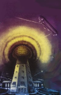
 Tesla's "Magnifying Transmitter", at Wardenclyffe, Shoreham, LI (New York). The transmitting station is an octagonal tower, pyramidal in shape, and some 187 feet in height. It consists of huge wooden stilts, heavily braced, and reinforced, and surmounted by a cupola of interlaced steel wires, bent so as to form an arc. In the cupola there is a wooden platform occupying its entire width. Mr. Tesla began work on his transmitting station about eighteen months ago.
When he first came there, and it was understood that J. Pierpont Morgan had become interested in his odd enterprise and furnished him with financial assistance, a thrill of vague expectancy ran through the little settlement, The Wardenclyffe Land Company, which owns practically all the available ground in the vicinity, gave the inventor a free grant of some 175 acres of fine land, and then settled down to wait for the day when Wardenclyffe would become the centre of the universe.
Tesla's "Magnifying Transmitter", at Wardenclyffe, Shoreham, LI (New York). The transmitting station is an octagonal tower, pyramidal in shape, and some 187 feet in height. It consists of huge wooden stilts, heavily braced, and reinforced, and surmounted by a cupola of interlaced steel wires, bent so as to form an arc. In the cupola there is a wooden platform occupying its entire width. Mr. Tesla began work on his transmitting station about eighteen months ago.
When he first came there, and it was understood that J. Pierpont Morgan had become interested in his odd enterprise and furnished him with financial assistance, a thrill of vague expectancy ran through the little settlement, The Wardenclyffe Land Company, which owns practically all the available ground in the vicinity, gave the inventor a free grant of some 175 acres of fine land, and then settled down to wait for the day when Wardenclyffe would become the centre of the universe.
Some of the farmers who come to Wardenclyffe to send their products to this city look at Mr. Tesla's tower, which is situated directly opposite the railroad station, and shake their heads sadly. They are inclined to take a skeptical view regarding the feasibility of the wireless "world telegraphy" idea, but yet Tesla's transmitting tower as it stands in lonely grandeur and boldly silhouetted against the sky on a wide clearing on the concession is a source or great satisfaction and of some mystification to them all.
"It is a mighty fine tower," said one food farmer to a visitor last week. "The breeze up there is something grand on a Summer evening, and you can see the Sound and all the steamers that go by. We are tired, though, trying to figure out why he put it here instead of at Coney Island." While the tower itself is very "stagy" and picturesque, it is the wonders that are supposed to be hidden in the earth underneath it that excite the curiosity of the population in the little settlement.
In the centre of the wide concrete platform which serves as a base for the structure there is a wooden affair very much like the companionway on an ocean steamer. The tower and the enclosure in which it has been built are being carefully guarded these days, and no one except Mr. Tesla's own men are allowed to approach it. Only they have been allowed as much as the briefest peep down the companionway. Mr. Scherff, the private secretary of the inventor, told an inquirer that the companionway led to a small drainage passage built for the purpose of keeping the ground about the tower dry.
But such of the villagers as saw the tower constructed tell a different story. They declare that it leads to a well-like excavation as deep as the tower is high with walls of mason work and a circular stairway leading to the bottom.
From there, they say, tunnels have been built in all directions, until the entire ground below the little plain on which the tower is raise
 d has been honeycombed with subterranean passages.
They tell with awe how Mr. Tesla, on his weekly visits to Wardenclyffe, spends as much time in the underground passages as he does on the tower or in the handsome laboratory and workshop erected beside it, and where the power plant for the world telegraph has been installed.
d has been honeycombed with subterranean passages.
They tell with awe how Mr. Tesla, on his weekly visits to Wardenclyffe, spends as much time in the underground passages as he does on the tower or in the handsome laboratory and workshop erected beside it, and where the power plant for the world telegraph has been installed.
No instruments have been installed as yet in the transmitter, nor has Mr. Tesla given any description of what they will be like. But in his article he announces that he will transmit from the tower an electric wave of a total maximum activity of ten million horse power. This, he says, will be possible with a plant of but 100 horse power, by the use of a magnifying transmitter of his own invention and certain artifices which he promises to make known in due course. What he expects to accomplish is summed up in the closing paragraph as follows:
"When the great truth, accidentally revealed and experimentally confirmed, is fully recognized, that this planet, with all its appalling immensity, is to electric currents virtually no more than a small metal ball and that by virtue of this fact many possibilities, each baffling imagination and of incalculable consequence, are rendered absolutely sure of accomplishment; when the first plant is inaugurated and it is shown that a telegraphic message, almost as secret and non-interferable as a thought, can be transmitted to any terrestrial distance, the sound of the human voice, with all its intonations and inflections faithfully and instantly reproduced at any other point of the globe, the energy of a waterfall made available for supplying light, heat or motive power, anywhere...on sea, or land, or high in the air...humanity will be like an ant heap stirred up with a stick. See the excitement coming!" "Cloud born Electric Wavelets To Encircle the Globe: This Is Nikola Tesla's Latest Dream, and the Long Island Hamlet of Wardenclyffe Marvels Thereat," New York Times, 27 March 1904.
Let's continue:
As a young man, Nikola Tesla talked often of the possibility of interplanetary communication. Influenced by Buddhist philosophy and the thinking of Ernst Mach, Tesla began to develop a cosmology that tried to get at the heart of what life was and simultaneously discover electricity's role in the process. He believed in the concept of an all-pervasive aether and also believed that machines could be developed that would have the capability of thinking for themselves.
"The Problem of Increasing Human Energy", which was published 100 years ago (as of June 2000) in Century Magazine spells out Tesla's thoughts and visions for the future of mankind. This was written at the pinnacle of Tesla's life, when he was full of vigor, fresh from his startling accomplishments with the complete victory of his alternating current system over Edison's direct current system. In a radical departure from his previous writings which were of a technical nature, Tesla reveals his philosophy and hopes for humankind. In the article, Tesla expressed his belief that all of us are responsible for increasing the human mass, morally, intellectually, and physically. It was a radical article then... and in some circles... still be considered radical. Nonetheless it caught the eye of JP Morgan who financed Tesla's biggest dream... and most devastating disappointment.. Wardenclyffe! With the tower he had planned for the site, Tesla was going to power the world and light the oceans...A Fascinating Vision...However, powerful economic roadblocks stood in the way that drove Tesla deep into bankruptcy and culminated in the mindless destruction of the tower at Wardenclyffe.
CREDIT: The Electrical Experimenter, Dec. 1917.
Tesla's World Of Tomorrow
Tesla's life changed dramatically after Wardenclyffe. Initially his focus was on developing his bladeless turbine; but always his thoughts turned towards the revival of Wardenclyffe and his beloved Magnifying Transmitter. In 1925, his ideas on the wireless transmission of power were briefly entertained by the Bureau of Standards, but were abruptly rejected out of hand... due to the ignorance of how Tesla's system worked.
As an elderly man, Tesla discussed controversial topics such as free energy, particle beam weapons, cosmic rays that travel faster than light speed, a new magnifying transmitter which could harness these cosmic rays, interplanetary communication and also the claim that he could transmit energy at twice the speed of light.
The identification of each separate invention became a somewhat confusing task for journalists and researchers because each of these ideas involve the transmission of energy to distant places: and the so called “death ray” apparently, in its final form, comprised features from some, if not all of the other inventions above.
It is these exotic inventions that interest and fuels the free energy researchers imagination. It was Tesla's claim that he could transmit energy at twice the speed of light that brought Tesla in direct conflict with Einstein's suggestion that space was curved--the conventional mode of thought at the time. Tesla's unique views on the nature of radioactivity also placed him out of the mainstream scientific world. Was Tesla simply delusional ... or did he indeed have a keen insight into the wheel work of Nature? Time will tell. See " Tesla's Flying Machine " for more information on this incredible artist rendition - left.
Tesla's World of Tomorrow :
![]() We are an the threshold of a gigantic revolution, based on the commercialization of the wireless transmission of power.
We are an the threshold of a gigantic revolution, based on the commercialization of the wireless transmission of power.
![]() Motion pictures will be flashed across limitless spaces.
Motion pictures will be flashed across limitless spaces.
![]() The same energy (wireless transmission of power) will drive airplanes and dirigibles from one central base.
The same energy (wireless transmission of power) will drive airplanes and dirigibles from one central base.
![]() In rocket-propelled machines... it will be practicable to attain speeds of nearly a mile a second (3600 m.p.h.) through the rarefied medium above the stratosphere.
In rocket-propelled machines... it will be practicable to attain speeds of nearly a mile a second (3600 m.p.h.) through the rarefied medium above the stratosphere.
![]() I have fame and untold wealth, more than this, and yet, how many articles have been written in which I was declared to be an impractical unsuccessful man, and how many poor, struggling writers have called me a visionary. Such is the folly and shortsightedness of the world! Nikola Tesla
I have fame and untold wealth, more than this, and yet, how many articles have been written in which I was declared to be an impractical unsuccessful man, and how many poor, struggling writers have called me a visionary. Such is the folly and shortsightedness of the world! Nikola Tesla
![]() We will be enabled to illuminate the whole sky at night...Eventually we will flash power in virtually unlimited amounts to planets... Nikola Tesla.
We will be enabled to illuminate the whole sky at night...Eventually we will flash power in virtually unlimited amounts to planets... Nikola Tesla.
CREDIT: The Electrical Experimenter, December, 1917
NIKOLA TESLA'S WIRELESS WORK
Nikola Tesla's Wireless Work; The Creation of Tesla’s Magnifying Transmitter
Wardenclyffe, Shoreham, Long Island
"The tower was destroyed two years ago but my projects are being developed and another one, improved in some features, will be constructed. . . . My project was retarded by laws of nature. The world was not prepared for it. It was too far ahead of time, but the same laws will prevail in the end and make it a triumphal success." Nikola Tesla 1917
The Generation and Transmission of Electrical Energy
The Dynamo-Electric Machine and Two-Wire Transmission
1886 patent illustration, showing elements of an electrical generator connected to a closed two-wire circuit.
The above illustration taken from Nikola Tesla’s 1886 patent “Regulator for Dynamo-Electric Machines” shows portions of a closed two-wire circuit consisting of a generator and multiple loads wired in series. As described in the patent, M and M’ are “one core of the field magnets,” and “a and b are the positive and negative brushes of the main or working circuit, and c is the auxiliary brush. The working circuit D extends from the brushes a and b as usual, and contains electric lamps or other devices, D’, either in series or in multiple arc.” [Dr. Nikola Tesla Complete Patents, pp. 8-11] This is a direct current machine, such as might have been used as part of Edison’s DC power distribution system.
Radio-Frequency Power Supplies
The Radio Frequency Alternator
Nikola Tesla ’s research in the area of wireless telecommunications and alternating current power transmission began in 1888. At the time he was involved in the design and manufacture of rotating machinery for the fledgling electric power industry. In the course of this work he occasionally had opportunity to run a particular alternator at high speeds (in the area of 10,000 RPM) developing currents around 2,000 cycles per second, or 2 kHz. The circuits also included, “transformers, etc., and condensers.” The phenomena he observed “were entirely new” and of a nature leading him to believe that a solution to the problem of wireless energy transmission might be found therein. [Inventions, Researches and Writings of Nikola Tesla, 1894, pp. 152-155; Nikola Tesla On His Work With Alternating Currents and Their Application to Wireless Telegraphy, Telephony, and Transmission of Power, pp. 1-8]

This machine was run up to 12,000 rpm, and had an output of about 8 kilowatts. It had an internal resistance of only 1/40 of an ohm and was used by Tesla “for all sorts of wireless demonstrations.” Tesla’s symbolic representation of an electrical alternator appears to the left. [Nikola Tesla On His Work With Alternating Currents and Their Application to Wireless Telegraphy, Telephony, and Transmission of Power, p. 16-17]
The “Inductorium” or “Commercial Coil”
“Inductorium” is an archaic term for the commercial iron-core induction coil transformer, common during Tesla’s time. Once again, the symbolic representation is to the left. [ EXPERIMENTS WITH ALTERNATE CURRENTS OF VERY HIGH FREQUENCY AND THEIR APPLICATION TO METHODS OF ARTIFICIAL ILLUMINATION, Delivered before the American Institute of Electrical Engineers, Columbia College, N.Y., May 20, 1891 (Inventions, Researches and Writings of Nikola Tesla, pp. 145-197).]
The high-tension induction coil or “Tesla coil”
Tesla made improvements to the commercial coil resulting in the design shown above. In operation, the inner turns of the two secondary windings are held at a relatively low potential. This strengthening reduces the chance of arc-over to the coil’s primary windings. [ EXPERIMENTS WITH ALTERNATE CURRENTS OF HIGH POTENTIAL AND HIGH FREQUENCY , Delivered before the Institution of Electrical Engineers, London, February 1892 (Inventions, Researches and Writings of Nikola Tesla, pp. 198-293).]
The Transmission of Radio-Frequency Electrical Energy
Two striking results lead Tesla to the conclusion that the wireless transmission of electrical energy was feasible. Both involved the operation of the high frequency alternator paired up with an induction coil transformer.
One-Wire Transmission
The first to be demonstrated was the operation of light and motive devices connected by a single wire to only one terminal of the high frequency coil, presented in the 1891 lecture EXPERIMENTS WITH ALTERNATE CURRENTS OF VERY HIGH FREQUENCY AND THEIR APPLICATION TO METHODS OF ARTIFICIAL ILLUMINATION (Inventions, Researches and Writings of Nikola Tesla, pp. 156-172; Nikola Tesla On His Work With Alternating Currents and Their Application to Wireless Telegraphy, Telephony, and Transmission of Power, p. 7).
Apparatus for the demonstration of one-wire transmission
I have stated above that a body enclosed there is no difficulty whatever in bringing a wire or filament to any degree of incandescence by simply connecting it to one terminal of a coil of the proper dimensions. Thus, if the well-known apparatus of Prof. Crookes, consisting of a bent platinum wire with vanes mounted over it (Fig. 18 / 114), be connected to one in an unexhausted bulb may be intensely heated by simply connecting it with a source of rapidly alternating potential. The heating in such a case is, in all probability, due mostly to the bombardment of the molecules of the gas contained in the bulb. When the bulb is exhausted, the heating of the body is much more rapid, and terminal of the coil—either one or both ends of the platinum wire being connected—the wire is rendered almost instantly incandescent, and the mica vanes are rotated as though a current from a battery were used: A thin carbon filament, or, preferably, a button of some refractory material (Fig. 19 / 115), even if it be a comparatively poor conductor, inclosed in an exhausted globe, may be rendered highly incandescent; and in this manner a simple lamp capable of giving any desired candle power is provided.
While a single terminal lamp connected to one of an induction coil’s secondary terminals does not form a closed circuit, “in the ordinary acceptance of the term” the circuit is closed in the sense that a return path is established back to the secondary by what Tesla called “electrostatic induction” (or so called displacement currents). This is due to the fact that the lamp’s filament or refractory button has capacitance relative to the coil’s free terminal and environment and the secondary’s free terminal also has capacitance relative to the lamp and environment.
More on One-Wire Transmission
Tesla gave some additional thoughts on the concept of energy transmission through one wire without return in the lecture ON LIGHT AND OTHER HIGH FREQUENCY PHENOMENA delivered before the Franklin Institute, Philadelphia, February 1893, and before the National Electric Light Association, St. Louis, March 1893 [Inventions, Researches and Writings of Nikola Tesla, pp. 294-373].
In Fig. 20 I / 184 I. is shown a plan which has been followed in the study of the resonance effects by means of a high frequency alternator. C1 is a coil of many turns, which is divided into small separate sections for the purpose of adjustment. The final adjustment was made sometimes with a few thin iron wires (though this is not always advisable) or with a closed secondary. The coil C1 is connected with one of its ends to the line L from the alternator G and with the other end to one of the plates C of a condenser C C1, the plate (C1) of the latter being connected to a much larger plate P1. In this manner both capacity and self-induction were adjusted to suit the dynamo frequency.
As regards the rise of potential through resonant action, of course, theoretically, it may amount to anything since it depends on self-induction and resistance and since these may have any value. But in practice one is limited in the selection of these values and besides these, there are other limiting causes. One may start with, say, 1,000 volts and raise the E. M. F. to 50 times that value, but one cannot start with 100,000 and raise it to ten times that value because of the losses in the media which are great, especially if the frequency is high. It should be possible to start with, for instance, two volts from a high or low frequency circuit of a dynamo and raise the E. M. F. to many hundred times that value. Thus coils of the proper dimensions might be connected each with only one of its ends to the mains from a machine of low E. M. F., and though the circuit of the machine would not be closed in the ordinary acceptance of the term, yet the machine might be burned out if a proper resonance effect would be obtained. I have not been able to produce, nor have I observed with currents from a dynamo machine, such great rises of potential. It is possible, if not probable, that with currents obtained from apparatus containing iron the disturbing influence of the latter is the cause that these theoretical possibilities cannot be realized. But if such is the case I attribute it solely to the hysteresis and Foucault current losses in the core.
Generally it was necessary to transform upward, when the E. M. F. was very low, and usually an ordinary form of induction coil was employed, but sometimes the arrangement illustrated in Fig. 20 II., has been found to be convenient. In this case a coil C is made in a great many sections, a few of these being used as a primary. In this manner both primary and secondary are adjustable. One end of the coil is connected to the line L1 from the alternator, and the other line L is connected to the intermediate point of the coil. Such a coil with adjustable primary and secondary will be found also convenient in experiments with the disruptive discharge. When true resonance is obtained the top of the wave must of course be on the free end of the coil as, for instance, at the terminal of the phosphorescence bulb B. This is easily recognized by observing the potential of a point on the wire w near to the coil.
Two additional examples of one-wire transmission
Tesla shows two additional examples of one-wire transmission. In the arrangement labeled I above, his intention is to show the effect of resonance in promoting the movement of energy along conductor L. Arrangement II diagrams a self-induction coil with a tap near one end, effectively dividing the coil primary and secondary sections. It shows one-wire transmission from the transformer’s free terminal to a single terminal lamp. In both cases, conductor L1 constitutes a part of the return circuit. Also notice the two vertical lines to the extreme left and right in the illustration. These appear to represent the walls of an enclosed space, or, perhaps, nearby parts of the general environment.
Wireless Transmission
The second result demonstrated how energy could be made to go through space without any connecting wires. This was the first step towards a practical wireless system.
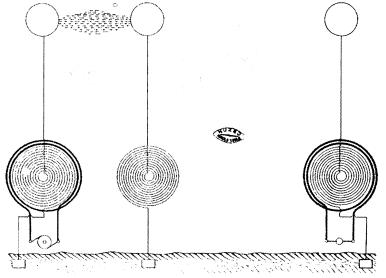
The most striking result obtained – two vacuum tubes lighted in an alternating electrostatic field while held in the hand of the experimenter.
The wireless energy transmission effect involved the creation of an electric field between two metal plates, each being connected to one terminal of the induction coil’s secondary winding. Once again, a light-producing device was used as a means of detecting the presence of the transmitted energy.
The ideal way of lighting a hall or room would, however, be to produce such a condition in it that an illuminating device could be moved and put anywhere, and that it is lighted, no matter where it is put and without being electrically connected to anything. I have been able to produce such a condition by creating in the room a powerful, rapidly alternating electrostatic field. For this purpose I suspend a sheet of metal a distance from the ceiling on insulating cords and connect it to one terminal of the induction coil, the other terminal being preferably connected to the ground [type-one]. Or else I suspend two sheets as illustrated in Fig. 29 / 125, each sheet being connected with one of the terminals of the coil [type-two], and their size being carefully determined.
An exhausted tube may then be carried in the hand anywhere between the sheets or placed anywhere, even a certain distance beyond them; it remains always luminous. [EXPERIMENTS WITH ALTERNATE CURRENTS OF VERY HIGH FREQUENCY AND THEIR APPLICATION TO METHODS OF ARTIFICIAL ILLUMINATION, Inventions, Researches and Writings of Nikola Tesla, pp. 188-189; Nikola Tesla On His Work With Alternating Currents and Their Application to Wireless Telegraphy, Telephony, and Transmission of Power, pp. 7-8]
Transmitter type-one: a source consisting of a single metal sheet suspended a distance from the ceiling on insulating cords and connected to one terminal of an induction coil, the other terminal being connected to the ground. [NTAC]
Transmitter type-two: a source consisting of two metal sheets suspended a distance from the ceiling on insulating cords, each sheet being connected with one of the terminals of an induction coil.
Theory of Wireless Transmission
In working to develop an explanation of the two observed effects mentioned above, Tesla recognized that electrical energy could be projected outward into space and detected by a receiving instrument in the general vicinity of the source without a requirement for any interconnecting wires. He went on to develop two theories related to these observations.
1) By using two type-one sources positioned at distant points on the earth’s surface, it is possible to induce a flow of electrical current between them.
2) By incorporating a portion of the earth as part of a powerful type-two oscillator the disturbance can be impressed upon the earth and detected “at great distance, or even all over the surface of the globe.”
Tesla also made an assumption that Earth is a charged body floating in space.
A point of great importance would be first to know what is the capacity of the earth? and what charge does it contain if electrified? Though we have no positive evidence of a charged body existing in space without other oppositely electrified bodies being near, there is a fair probability that the earth is such a body, for by whatever process it was separated from other bodies—and this is the accepted view of its origin—it must have retained a charge, as occurs in all processes of mechanical separation.
Tesla was familiar with demonstrations that involved the charging of Leiden jar capacitors and isolated metal spheres with electrostatic influence machines. By bringing these elements into close proximity with each other, and also by making direct contact followed by their separation the charge can be manipulated. He surely had this in mind in the creation of his mental image, not being able to know that the model of Earth’s origin was inaccurate. The presently accepted model of planetary origin is one of accretion and collision.
If it be a charged body insulated in space its capacity should be extremely small, less than one-thousandth of a farad.
We now know that the earth is, in fact, a charged body, made so by processes—at least in part—related to an interaction of the continuous stream of charged particles called the solar wind that flows outward from the center of our solar system and Earth’s magnetosphere.
But the upper strata of the air are conducting, and so, perhaps, is the medium in free space beyond the atmosphere, and these may contain an opposite charge. Then the capacity might be incomparably greater.
We also know one of the upper strata of Earth’s atmosphere, the ionosphere, is conducting.
In any case it is of the greatest importance to get an idea of what quantity of electricity the earth contains.
An additional condition of which we are now aware is that the earth possesses a naturally existing negative charge with respect to the conducting region of the atmosphere beginning at an elevation of about 50 Km. The potential difference between the earth and this region is on the order of 400,000 volts. Near the earth's surface there is a ubiquitous downward directed E-field of about 100 V/m. Tesla referred to this charge as the “electric niveau” or electric level [As noted by James Corum, et al in the paper "Concerning Cavity Q," PROCEEDINGS OF THE 1988 INTERNATIONAL TESLA SYMPOSIUM, and others.]
It is difficult to say whether we shall ever acquire this necessary knowledge, but there is hope that we may, and that is, by means of electrical resonance. If ever we can ascertain at what period the earth's charge, when disturbed, oscillates with respect to an oppositely electrified system or known circuit, we shall know a fact possibly of the greatest importance to the welfare of the human race. I propose to seek for the period by means of an electrical oscillator, or a source of alternating electric currents. . . .
Assume that a source of alternating currents be connected, as in Fig. 21 / 185, with one of its terminals to earth (conveniently to the water mains) and with the other to a body of large surface P. . . . I think that beyond doubt it is possible to operate electrical devices in a city through the ground or pipe system by resonance from an electrical oscillator located at a central point. But the practical solution of this problem would be of incomparably smaller benefit to man than the realization of the scheme of transmitting intelligence, or perhaps power, to any distance through the earth or environing medium. If this is at all possible, distance does not mean anything. Proper apparatus must first be produced by means of which the problem can be attacked and I have devoted much thought to this subject. I am firmly convinced that it can be done and hope that we shall live to see it done. [ ON LIGHT AND OTHER HIGH FREQUENCY PHENOMENA, delivered before the Franklin Institute, Philadelphia, and the National Electric Light Association, St. Louis, 1893, (Inventions, Researches and Writings of Nikola Tesla, 1894, pp. 294-373).]
The High Tension Induction Coil
The above described arrangements refer only to the use of commercial coils as ordinarily constructed. If it is desired to construct a coil for the express purpose of performing with it such experiments as I have described, or, generally, rendering it capable of withstanding the greatest possible difference of potential, then a construction as indicated in Fig. 17 / 113 will be found of advantage. The coil in this case is formed of two independent parts which are wound oppositely, the connection between both being made near the primary. The potential in the middle being zero, there is not much tendency to jump to the primary and not much insulation is required. In some cases the middle point may, however, be connected to the primary or to the ground. In such a coil the places of greatest difference of potential are far apart and the coil is capable of withstanding an enormous strain. The two parts may be movable so as to allow a slight adjustment of the capacity effect. [Inventions, Researches and Writings of Nikola Tesla, pp. 172-173]
A Tesla high-tension induction coil
The optimized type-two transmitter consists of two elevated metal plates, each plate being connected to one of the terminals of a Tesla high-tension induction coil.
Modification of the optimized type-two transmitter. This circuit is the result of interpolation of the preceding and following diagrams, which are of historical record
The modified type-two transmitter shown above consists of two elevated metal plates, each plate being connected to one of the induction coil’s high-voltage terminals. While the coil’s left-hand primary winding remains the same, i.e., it is still closely coupled to the left-hand secondary, the right-hand primary has been removed. This means the right-hand coil is no longer energized by induction. Using Tesla’s terminology, it is now an extra coil. [Some adjustment might be required to bring the extra coil back into resonance with left-hand secondary.] The extra coil is energized or receives energy by one-wire transmission through the interconnecting section of wire.
A further modification of a type-two transmitter, this circuit represents the preferred prototype transmitter design developed in 1899 at the Colorado Springs experimental station. The transmitter circuit now consists of separate two elements, an alternator-driven oscillator and an adjacent free oscillatory system.
In the further modified type-two transmitter shown above the two halves of the transformer have been physically separated. The transmitter now consists of two discrete units. The oscillator is on the left with its elevated plate still connected to the upper secondary terminal. The free system on the right consists of the original elevated plate connected to the upper terminal of the extra coil. Instead of a wire connecting the lower secondary and lower extra coil terminals, the two coils are now connected to individual earth grounds. These ground connections are constructed so as to introduce the least possible resistance to the earth. In operation a powerful current flows through the subsurface between the two ground terminals. An interaction also takes place between the two elevated terminals. Tesla believed the electrical disturbance would extend to a great distance from the transmitter, possibly across the globe.
Colorado Springs Experimental Station
In 1899 Tesla established the Colorado Springs experimental station. The apparatus he assembled there served as a test bed with which to evaluate the type-two and type-one transmitter configurations described above, along with variations of the same. Tesla settled upon the six arrangements shown in the Colorado Springs Notes on pages 190 and 191, and also on page 200.
Tesla’s own sketches of the 6 transmitter configurations developed at the Colorado Spring’s experimental station [C/S #s 1, 2, 3, 4, 5 & 6]. Tesla’s rendering the last of these at a slightly larger scale than the rest reflects his enthusiasm for the design. [CSN, pp. 190-191, 200]
Figure 1 is a type-one transmitter and 2 through 4 are modifications thereof; 5 and 6 are type-two transmitters. Tesla felt arrangement #6 was the most promising. It shows up with slight variations at a number of places in the Colorado Springs Notes, most significantly on pages 191, 200, 197 and 170 (see also pages 161, 162, 174, 177 and 184). In the corresponding text on page 191 Tesla writes, "In Fig. 5. & 6. it is found best to make [the] extra coil 3/4 wave length and the secondary 1/4 for obvious reasons." This two-coil/two-ground configuration was incorporated into the initial Wardenclyffe design.
This is a basic rendering of the type-two transmitter configuration, the same design as that illustrated in the Colorado Springs Notes [type-two, C/S #6]. A receiving circuit is standing out to the right. This general configuration was to be incorporated into the initial Wardenclyffe design, but it was not implemented. [RARE NOTES FROM TESLA ON WARDENCLYFFE, Leland Anderson, Electric Spacecraft Journal, Apr./May/June, # 26, 1998; See also “ Wardenclyffe and the World System.”]
The U.S. AND-logic gate patents Method of Signaling, No. 723,188 and System of Signaling, No. 725,605, show a similar arrangement; only the transmitter consists of two electrically driven oscillators tuned to different frequencies instead the single-frequency oscillator-plus-extra coil combination. Also, the transmitter has a common ground. The original application filing date is July 16, 1900 and it is probable that the Wardenclyffe installation, as initially proposed, would have taken on some attributes of this configuration, along with some modifications. For example, each transmitter secondary could be provided with a dedicated ground, and perhaps an independent high voltage power supply as well. Also, it has been suggested that if each transmitter was to be nearly in tune with its partner—say having only a 12 Hz difference in vibration rate—a low-frequency beat tone would be produced, thus introducing an ELF component to the wave complex.
Drawings from the U.S. AND-logic gate patent METHOD OF SIGNALING, No. 723,188
[improved type-one, C/S #1]. [Dr. Nikola Complete Patents, p. 409]
The Wardenclyffe Plant
The initial conceptual plan for Wardenclyffe discussed above was tied in with the idea Tesla had that it might be possible to produce global displacements of the earth’s charge using a powerful type-two transmitter. In theory, the local electrical current flowing in the earth between the two ground terminals causes this widespread charge displacement. By using an appropriate resonant frequency, that is to say, one at which Earth itself would oscillate, the degree of charge displacement would increase over time.
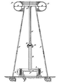
The initial Wardenclyffe design plan called for the installation of two 600-foot tall towers in relatively close proximity to each other. The two-tower idea could not be implemented due to financial constraints, which led to a series of modifications. The first of these led to the arrangement shown in a sketch dated May 29, 1901 (to the left in figure below). An electrical oscillator or discharging circuit, consisting of a resonance transformer and an extra coil, is coupled to the tower structure through an adjustable air gap. The tower cupola is supported on electrically conducting legs, which, in turn, are attached to a substantial grounding system. The capacitance of the cupola relative to the environment and the high-potential oscillator terminal, along with the inductance of the tower legs comprise a separate resonant LC circuit which Tesla designated the “free system.”
Two design drawings, with variations, of the initial Wardenclyffe transmitter design of 1901 [modified type-two, C/S #5/6]. Notice the independent grounds. [Tesla calculated the legs would have to be at least 600 feet in length.] Notice also the alternator-driven oscillator and the adjoining free oscillatory system. . [RARE NOTES FROM TESLA ON WARDENCLYFFE, Leland Anderson, Electric Spacecraft Journal, Apr./May/June, # 26, 1998]
The right-hand diagram above includes a low-frequency alternator and high-voltage power supply transformer connected to a disruptive-discharge type oscillator. The circuit incorporates a dual inductor-capacitor [LC] arrangement in the oscillatory transformer primary tank circuit along with dual secondary windings. Independent tuning the two sides of the circuit to different frequencies (n/4 lambda, n being an uneven number) would result in the development of a higher order wave complex beyond the fundamental resonant frequency of the extra coil. [“The transmitter was to emit a wave-complex of special characteristics. . . .” MY INVENTIONS; “. . . the transmitter was designed to emit a wave-complex exactly matching the [receiver] combination in the number and pitch of individual vibrations, their groupment and order of succession. . . .” TESLA'S TIDAL WAVE TO MAKE WAR IMPOSSIBLE, English Mechanic and World of Science, May 3, 1907, p. 296.]
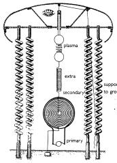
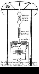
Modified Wardenclyffe transmitter design. [RARE NOTES FROM TESLA ON WARDENCLYFFE, Leland Anderson, Electric Spacecraft Journal, Apr./May/June, # 26, 1998]
In the above figure the straight conducting legs have assumed a spiral form. An obvious advantage would be a reduction in the structure’s overall height above ground level. Also, notice that the number of turns varies from leg to leg. This would also result in the development of what might be called a higher order wave complex by the transmitter—allowing a form of spread-spectrum frequency-division multiplexing.
Tesla began operational testing of the Wardenclyffe plant in July 1903 and it appears that he was not at all satisfied with its’ performance. While it is possible a type-two transmitter could be made to work properly, it can be seen that he experienced difficulty with the single-tower implementation of the design. His experiments with the 1899 through 1901 configuration led him to write his underwriter J.P. Morgan on November 5, 1903,
Dear Mr. Morgan:-
The enclosed bears out my statement made to you over a year and a half ago. The old plant has never worked beyond a few hundred miles. Apart of imperfections of the apparatus design there were four defects, each of which was fatal to success. It does not seem probable that the new plant will do much better, for these faults were of a widely different nature and difficult to discover.
As to the remedies, I have protected myself in applications filed 1900-1902, still in the office.
Yours faithfully,
N. Tesla
The "old plant" refers to the Colorado Springs Experimental Station or perhaps an initial Wardenclyffe installation bearing some resemblance to it.
As for the "remedies" protected in applications filed between 1900 and 1902, and "still in the office," the only patented invention meeting these criteria is APPARATUS FOR TRANSMITTING ELECTRICAL ENERGY, No. 1,119,732, issued Dec. 1, 1914. Comparing the two basic circuits the most obvious difference is the elimination of the stand-alone extra coil or free [oscillating] system and the plasma coupler [type-two, C/S #6]. The entire transmitter is now comprised solely of the discharging circuit—an oscillatory transformer with an extra coil connected directly to the elevated terminal [type-one, C/S #1].
The Magnifying Transmitter
The 1902 transmitter constituted a departure from the earlier type-two transmitter planned for the Wardenclyffe facility. The new design was a type-one transmitter in which a second conducting path would be established in the upper half-space between plant’s elevated terminal and that of the distant receiving facility. [Type-one, C/S #1; APPARATUS FOR TRANSMITTING ELECTRICAL ENERGY, No. 1,119,732, Dr. Nikola Tesla Complete Patents. p. 435]
Other defects of the Colorado apparatus could have been the antenna feed point (see CSN, pp. 170, 197) and also the slender mast in contrast to the large diameter elevated capacity—either an oblate spheroid or toroid shaped—used in the Wardenclyffe design), the 1:1 aspect ratio C/S extra coil verses the 9.1:1 aspect ratio extra coil shown in the 1914 patent, and the shallow Colorado ground plate verses the 300-foot long section of pipe at the bottom of a 120-foot deep shaft [see The Connection to Earth]. [Further differences between the Colorado Springs layout and the Long Island plant?] Also the considerable distance (about 350 feet) between the high-voltage power supply transformers and the tower-side components, including, at the very least, a helical resonator, could have been a problem on Long Island. Two other seemingly applicable patents filed for within the specified time period and patented in 1900 are “Means for Increasing the Intensity of Electrical Oscillations,” No. 787,412 and “Method of Insulating Electrical Conductors,” No. 655,838, reissued as No. 11,865. Both of these inventions might have been useful for improving the Wardenclyffe plant's performance; the first for the magnifying transmitter itself, the second for improving high-voltage power transmission between the lab building and the tower structure.
In any case, it can be seen that some major modifications were made to the design. He later said,
I used the antenna. I used it right along up to 1907. I made my measurements and experiments, and I transmitted for the purpose of tests, energy and all that, but it never went further than is shown in the picture. [Nikola Tesla On His Work With Alternating Currents and Their Application to Wireless Telegraphy, Telephony, and Transmission of Power, Leland Anderson, Twenty First Century Books, p. 154
Functional Description of Tesla's Magnifying Transmitter
Based upon a series of experiments conducted between 1888 and 1907 Tesla concluded that the earth is an excellent electrical conductor. He believed an electric current c ould propagate to terrestrial distances of thousands of miles “without diminution of intention,” and made observations that, he felt, supported this supposition. He also found that Earth’s naturally existing electrical charge can be made to oscillate, and that “by impressing upon it current waves [i.e., surface waves] of certain lengths, definitely related to its diameter, the globe is thrown into resonant vibration like a wire, forming stationary waves.”
Its singleness is only an apparent limitation, for by impressing upon it numerous non-interfering vibrations, the flow of energy may be directed through any number of paths which, though bodily connected, are yet perfectly distinct and separate like ever so many cables. Any apparatus, then, which can be operated through one or more wires, at distances obviously limited, can likewise be worked without artificial conductors, and with the same facility and precision, at distances without limit other than that imposed by the physical dimensions of the globe.
It is intended to give practical demonstrations of these principles with the plant illustrated. . . . dictate instructions, and have them instantly appear in type elsewhere . . . talk to any telephone subscriber on the globe . . . hear anywhere music or  song, speech . . . picture, character, drawing, or print transferred from one to another place . . . millions of instruments operated from one plant . . . transmission of power shown . . . [“ The Future of the Wireless Art” Wireless Telegraphy & Telephony, Walter W. Massie & Charles R. Underhill, 1908, pp. 67-71]
Tesla felt the resistance of the Earth would be negligible due to its immense cross sectional area and relative shortness as compared to its diameter. (Corum & Corum) The key to good performance is a robust ground connection.
A [conducting] sphere of the size of a little marble offers a greater impediment to the passage of a current than the whole earth. . . . This is not merely a theory, but a truth established in numerous and carefully conducted experiments. [ibid]
. . . You must first understand certain things. Consider, for instance, the term "resistance." When you think of resistance you imagine, naturally, that you have a long, thin conductor; but remember that while resistance is directly proportionate to length, it is inversely proportionate to the section. It is a quality that depends on a ratio. If you take a small sphere of the same size of a pea, and compare its length with its section, you would find a certain resistance. Now you extend this pea to the size of the earth, and what is going to happen?
While the length increases, say a thousand times or a million times, the section increases with the square of the linear dimensions, so that the bigger this thing is the less resistance it has. Indeed, if the earth were as big as the sun we would still be better off than we are; we could readily telephone from one end of the sun to the other by the system, and the larger the planet the better it would be. . . . The resistance is only at the point where you get into the earth with your current. The rest is nothing. [Nikola Tesla On His Work With Alternating Currents and Their Application to Wireless Telegraphy, Telephony, and Transmission of Power, pp. 134-135]
Surface Waves
In 1916 Tesla stated in regards to the disposition of the “vibratory energy” of the oscillator,
By proper design and choice of wavelengths, you can arrange it so that you get, for instance, 5 percent in these electromagnetic waves and 95 percent in the current that goes through the earth. That is what I am doing. [Nikola Tesla On His Work With Alternating Currents and Their Application to Wireless Telegraphy, Telephony, and Transmission of Power, p. 132]
Tesla often spoke of the electrical disturbance being in the form of an electrical current flowing through the earth. As with any electrical current flowing through a conductor surrounded by an insulating medium, there is also an electrical disturbance in the material or space adjacent to that conductor. In the case of the World System, this is a surface wave traveling along the interface between the ground and the air. The wave energy is associated with the ground current. It does not radiate freely into space but tends to be concentrated near the surface of the conductor, i.e., the guiding surface. This is equivalent to the fields associated with an electrical current flowing in a wire.
126 x-Q. In this system, then, as you have described it, the current actually flows from the transmitter through the ground to the receiver; is that so?
Yes, sir; it does, in accordance with my understanding. In my Patent No. 649,621, “Apparatus for Transmission of Electrical Energy,” [May 15, 1900] it is stated distinctly:
“It is to be noted that the phenomenon here involved in the transmission of electrical energy is one of true conduction and is not to be confounded with the phenomena of electrical radiation, etc.”
The attractive feature of this plan was that the intensity of the signals should diminish very little with the distance, and, in fact, should not diminish at all, if it were not for certain losses occurring, chiefly in the atmosphere. [Nikola Tesla: Guided Weapons & Computer technology, Leland Anderson, Twenty First Century Books, p. 82]
Atmospheric Conductivity
The point-to-point type-one “air-ground system” depends upon passage of electrical current through both the earth and the atmosphere. To accommodate this, the Wardenclyffe-type World System transmitter/receiver facility includes both an air and a ground connection, each being called a “terminal.” Tesla clearly specified the earth as being one of the conducting media involved in ground and air system technology. The other specified medium is the atmosphere above 5 miles elevation. While not an ohmic conductor, in this region of the troposphere and upwards, the density or pressure is sufficiently reduced to so that, according to Tesla’s theory, the atmosphere’s insulating properties can be easily impaired, allowing an electric current to flow. His theory further states that the conducting region is developed through the process of atmospheric ionization, in which the effected portions thereof are changed to plasma. The presence of the magnetic fields developed by each plant’s helical resonator suggests that an embedded magnetic field and flux linkage is also involved. Flux linkage with Earth’s natural magnetic field is also a possibility.
The atmosphere below 5 miles is also viewed as a propagating medium for a portion of the aboveground circuit, and, being an insulating medium, electrostatic induction would be involved rather than true electrical conduction. Tesla felt that with a sufficiently high electrical potential on the elevated terminal the practical limitation imposed upon its height could be overcome. He anticipated that a highly energetic transmitter, as was intended at Wardenclyffe, would charge the elevated terminal to the point where the atmosphere around and above the facility would break down and become ionized, leading to a flow of true conduction currents between the two terminals by a path up to and through the troposphere, and back down to the other facility. The ionization of the atmosphere directly above the elevated terminals could be facilitated by the placement of a projection at the apex of the elevated terminal. Such projections are routinely used by Tesla coil builders to create a directed discharge. Alternatively, an ionizing beam of ultraviolet radiation could be used to form what might be called a high-voltage plasma transmission line.
In 1935 Tesla spoke about the transmission of propulsive power to ships at sea "through the stratosphere" using this technique.
The principles of this high tension power, generated by shore plants and transmitted through the upper reaches of the air, illuminating the sky, turning night into day and at the same time supplying power, have occupied Dr. Tesla's attention on and off now for the past thirty-five years. . . .
There is a method of conveying great power to ships at sea which would be able to propel them across oceans at high speed. . . .
The principle is this. A ray of great ionizing power is used to give to the atmosphere great powers of conduction. A high tension current of 10,000,000 to 12,000,000 volts is then passed along the ray to the upper strata of the air, which strata can be broken down very readily and will conduct electricity very well.
A ship would have to have equipment for producing a similar ionizing ray. The current which has passed through the stratosphere will strike this ray, travel down it and pass into the engines which propel the ship. ["Faster Liners is Tesla's Dream," New York Sun, June 5, 1935]
A minimal type-one system would be composed of two identical type-one facilities. Each would be capable of acting as a transmitter or a receiver, i.e. each could serve as either an energy source or as a load. The net flow of energy between the two plants would be dictated by the phase relationship between them and the relative level of activity. There would be two elevated terminals, one at each facility. The atmospheric path passes high potential, low current electrical energy through a somewhat resistive plasma transmission line running the entire distance between the two elevated terminals. Conversely, the low-resistance ‘ground’ path passes electrical energy of low potential and high current, flowing through the body of the earth.
It is well known, the higher the voltage that is passed across a conventional electrical power transmission line, the greater is its efficiency. This is due to the relationship between voltage and current as they pertain to power dissipation. For example, to power a hypothetical 100-watt load, the current can be one ampere at 100 volts, 10 amperes at 10 volts or 100 amperes at 1 volt, or any number of similar combinations. Every conductor, other than a superconductor, has a finite resistance. The voltage drop (E) across a resistance (R) is given by Ohm’s law, E = IR. For any given load, with a constant transmission-line resistance, by lowering the current (I) that flows through the transmission line, the voltage drop or loss is reduced. As can be seen by the inverse relationship between voltage and current, increasing the transmission-line voltage reduces the current. Conversely, the greater the current involved in powering a given load, the greater is the transmission-line loss, taken as a function of transmission-line resistance.
The above statements about transmission-line loss are also true in regards to the plasma transmission line that runs between the two elevated terminals. Tesla designed his transmitter with the expressed purpose of developing the greatest possible potential on the elevated terminal in order to minimize the loss due to the plasma transmission-line resistance. Looking at the Tesla type-one wireless energy transmission system, each of the two transmitter-receiver facilities serve, in a sense, as a lever and a fulcrum for conversion of the electrical energy flowing across the two different conducting paths. [Corum & Corum]
. . . by such means as have been described practically any potential that is desired may be obtained, the currents through the air strata may be rendered very small, whereby the loss in the transmission may be reduced. [ System of Transmission of Electrical Energy, U.S. Patent No. 645,576, Mar. 20, 1900]
The influence of resistance on transmission line efficiency depends upon the impedance of the source and the load. For example, if a power supply puts out one watt, but puts it out at one volt and one amp, then the output impedance of the source is one ohm. (R = E/I) The transmission line had better have much less resistance than one ohm (say 0.1 ohm or smaller) otherwise a significant portion of the transmitted energy will go into heating of the wire. In other words, the one volt, one amp source thinks the division between conductor and insulator is centered at the value of one ohm. A 100-ohm leakage path is nearly an insulator, since it dissipates only 1% of the output wattage. Now suppose the power supply puts out one watt at one kilovolt and one milliamp. In that case the source impedance is one megaohm, and the connecting wires had better be 100K or less in resistance. In this case a 10K resistor is a conductor of negligible resistance, and a one-megaohm leakage path will eat up half of the power supply's output.
Applying this relationship to a type-one Tesla coil transmission system, if the transmitter puts out one megawatt at one megavolts and one amp, then 100K is a fairly good conductor, and insulators have to measure 10 megaohms or better. In this case, if you could create a vertical plasma transmission line, and if the plasma filament measured 10 kilo-ohm, it would only consume 1% of the transmitter's power output. If the potential of transmitter's elevated terminal is raised to 100 megavolts at 10 mA (this is still 1 megawatt), then the supply impedance is 10,000 megaohms, and the plasma transmission line will act as a negligible series resistance even if its resistance is 100 megaohms. [The two preceding paragraphs are based upon an original text by William Beaty]
It was about 1896 when Tesla discovered that with a sufficiently high potential on the terminal plate (P1) he could modify the properties of the air in the vicinity of his apparatus, changing it from an insulator to a conductor
Up to the end of 1896, I had been developing the wireless system along the lines set forth in my lecture which is in the Martin book, particularly in the chapter on Electrical Resonance, pages 340-349. . . . But in experimenting with these high potential discharges which I was always producing, I discovered a wonderful thing. I found, namely, that the air, which had been behaving before like an insulator, suddenly became like a conductor; that is, when subjected to these great electrical stresses, it broke down and I obtained discharges which were not accountable for by the theory that the air was an insulator. When I calculated the effects, I concluded that this must be due to the potential gradient at a distance from the electrified body, and subsequently I came to the conviction that it would be ultimately possible, without any elevated antenna—with very small elevation—to break down the upper stratum of the air and transmit the current by conduction. [Nikola Tesla On His Work With Alternating Currents and Their Application to Wireless Telegraphy, Telephony, and Transmission of Power, p. 125]
Tesla described this effect as observed at the Colorado Springs Experimental Station in the patent “System of Transmission of Electrical Energy.”
. . . In illustration of these facts a few observations, which I have made with apparatus devised for the purposes here contemplated, may be cited. For example, a conductor or terminal, to which impulses such as those here considered are supplied, but which is otherwise insulated in space and is remote from any conducting-bodies, is surrounded by a luminous flame-like brush or discharge often covering many hundreds or even as much as several thousands of square feet of surface, this striking phenomenon clearly attesting the high degree of conductivity which the atmosphere attains under the influence of the immense electrical stresses to which it is subjected. This influence is however, not confined to that portion of the atmosphere which is discernible by the eye as luminous and which, as has been the case in some instances actually observed, may fill the space within a spherical or cylindrical envelop of a diameter of sixty feet or more, but reaches out to far remote regions, the insulating qualities of the air being, as I have ascertained, still sensibly impaired at a distance many hundred times that through which the luminous discharge projects from the terminal and in all probability much farther. The distance extends with the increase of the electromotive force of the impulses, with the diminution of the density of the atmosphere, with the elevation of the active terminal above the ground, and also, apparently, in slight measure, with the degree of moisture contained in the air.
I have likewise observed that this region of decidedly-noticeable influence continuously enlarges as time goes on, and the discharge is allowed to pass not unlike a conflagration which slowly spreads, this being possibly due to the gradual electrification or ionization of the air or to the formation of less insulating gaseous compounds. It is, furthermore, a fact that such discharges of extreme tensions, approximating those of lightning, manifest a marked tendency to pass upward away from the ground, which may be due to electrostatic repulsion, or possibly to slight heating and consequent rising of the electrified or ionized air. These latter observations make it appear probable that a discharge of this character allowed to escape into the atmosphere from a terminal maintained at a great height will gradually leak through and establish a good conducting-path to more elevated and better conducting air strata, a process which possibly takes place in silent lightning discharges frequently witnessed on hot and sultry days.
It will be apparent to what an extent the conductivity imparted to the air is enhanced by the increase of the electromotive force of the impulses when it is stated that in some instances the area covered by the flame discharge mentioned was enlarged more than sixfold by an augmentation of the electrical pressure, amounting scarcely to more than fifty per cent. As to the influence of rarefaction upon the electric conductivity imparted to the gases it is noteworthy that, whereas the atmospheric or other gases begin ordinarily to manifest this quality at something like seventy-five millimeters barometric pressure with the impulses of excessive electromotive force to which I have referred, the conductivity, as already pointed out, begins even at normal pressure and continuously increases with the degree of tenuity of the gas, so that at, say, one hundred and thirty millimeters pressure, when the gases are known to be still nearly perfect insulators for ordinary electromotive forces, they behave toward electromotive impulses of several millions of volts, like excellent conductors, as though they were rarefied to a much higher degree. . . . [Dr. Nikola Tesla Complete Patents, U.S. Patent No. 645,576, “System of Transmission of Electrical Energy,” pp. 312-313]
He was ionizing the air and creating plasma, which is electrically conductive. In light of this new understanding, he began to develop an alternative to the type-two-transmitter plan by which he might achieve wireless energy transmission.
Having discovered that, I established conditions under which I might operate in putting up a practical commercial plant. When the matter came up in the patents before the Examiner, I arranged this experiment for him in my Houston Street laboratory. [Nikola Tesla On His Work With Alternating Currents and Their Application to Wireless Telegraphy, Telephony, and Transmission of Power, p. 126]
Tesla’s diagram representing the arrangement of apparatus as demonstrated to G.D. Seeley.
This is a diagram representing the arrangement of apparatus as in a practical experiment which I performed before G.D. Seeley, Examiner in Chief, U.S. Patent Office, on the 23rd of January, 1898. This experiment illustrates a great departure I had made a little prior to that date. [Nikola Tesla On His Work With Alternating Currents and Their Application to Wireless Telegraphy, Telephony, and Transmission of Power, p. 125]
Tesla’s demonstration for the U.S. Patent Office, on January 23, 1898, at his Houston St. laboratory in New York City, was to show of the practicability of transmission of electrical energy in industrial amounts by the method and apparatus described in “System of Transmission of Electrical Energy,” U.S. Patent No. 645,576, dated March 20, 1900 and “Apparatus for Transmission of Electrical Energy,” U.S. Patent No. 649,621, dated May 15, 1900. The applications for both patents were filed September 2, 1897. [These are the initial patents specifically covering Tesla’s wireless system.]
In 1898 I made certain demonstrations before the Examiner-in-Chief of the Patent Office, Mr. Seeley, and it was upon showing him the practicability of the transmission that patents were granted to me. [Nikola Tesla On His Work With Alternating Currents and Their Application to Wireless Telegraphy, Telephony, and Transmission of Power, p. 27]
It might be argued the Colorado Springs experiments also served to demonstrate the technology in advance of patent issuance. The above-mentioned patents are dated March 20 and May 15, 1900, about 7 months after Tesla’s return to New York. The Wardenclyffe project served to further demonstrate and refine the method and apparatus, as described in the U.S. Patents “Art of Transmitting Electrical Energy Through the Natural Mediums,” No. 787,412, April 18, 1905 and “Apparatus for Transmitting Electrical Energy,” No. 1,119,732, December 1, 1914.
Tesla’s “World System” for wireless telegraphy, telephony and transmission of power was also to apply the principle of earth resonance.
If ever we can ascertain at what period the earth's charge, when disturbed, oscillates with respect to an oppositely electrified system or known circuit, we shall know a fact possibly of the greatest importance to the welfare of the human race. I propose to seek for the period by means of an electrical oscillator, or a source of alternating electric currents. One of the terminals of the source would be connected to earth as, for instance, to the city water mains, the other to an insulated body of large surface. It is possible that the outer conducting air strata, or free space, contain an opposite charge and that, together with the earth, they form a condenser of very large capacity. In such case the period of vibration may be very low and an alternating dynamo machine might serve for the purpose of the experiment. I would then transform the current to a potential as high as it would be found possible and connect the ends of the high tension secondary to the ground and to the insulated body. By varying the frequency of the currents and carefully observing the potential of the insulated body and watching for the disturbance at various neighboring points of the earth's surface resonance might be detected. Should, as the majority of scientific men in all probability believe, the period be extremely small, then a dynamo machine would not do and a proper electrical oscillator would have to be produced and perhaps it might not be possible to obtain such rapid vibrations. But whether this be possible or not, and whether the earth contains a charge or not, and whatever may be its period of vibration, it certainly is possible—for of this we have daily evidence—to produce some electrical disturbance sufficiently powerful to be perceptible by suitable instruments at any point of the earth's surface. [ ON LIGHT AND OTHER HIGH FREQUENCY PHENOMENA, Inventions, Researches and Writings of Nikola Tesla, 1894, p. 347.]
. . . It was clear to me from the very start that the successful consummation could only be brought about by a number of radical improvements. Suitable high frequency generators and electrical oscillators had first to be produced. The energy of these had to be transformed in effective transmitters and collected at a distance in proper receivers. Such a system would be manifestly circumscribed in its usefulness if all extraneous interference were not prevented and exclusiveness secured. In time, however, I recognized that devices of this kind, to be most effective and efficient, should be designed with due regard to the physical properties of this planet and the electrical conditions obtaining on the same.. [“ The True Wireless” Electrical Experimenter, May 1919]
When the earth is struck mechanically, as is the case in some powerful terrestrial upheaval, it vibrates like a bell, its period being measured in hours. When it is struck electrically, the charge oscillates, approximately, twelve times a second. By impressing upon it current waves of certain lengths, definitely related to its diameter, the globe is thrown into resonant vibration like a wire, stationary waves forming, the nodal and ventral regions of which can be located with mathematical precision. Owing to this fact and the spheroidal shape of the earth, numerous geodetical and other data, very accurate and of the greatest scientific and practical value, can be readily secured. Through the observation of these astonishing phenomena we shall soon be able to determine the exact diameter of the planet, its configuration and volume, the extent of its elevations and depressions, and to measure, with great precision and with nothing more than an electrical device, all terrestrial distances. In the densest fog or darkness of night, without a compass or other instruments of orientation, or a timepiece, it will be possible to guide a vessel along the shortest or orthodromic path, to instantly read the latitude and longitude, the hour, the distance from any point, and the true speed and direction of movement. By proper use of such disturbances a wave may be made to travel over the earth's surface with any velocity desired, and an electrical effect produced at any spot which can be selected at will and the geographical position of which can be closely ascertained from simple rules of trigonometry. [“The Future of the Wireless Art” 1908]
In fact, Tesla proposed two different methods by which global wireless energy transmission might be achieved. The first is by atmospheric conduction using two type-one facilities as described in the previous section. The second involves the use of earth resonance principles, the creation of manmade oscillations in Earth’s naturally existing electrical charge. This was made clear in a 1932 interview in which he makes a distinction between the transmission of electrical energy by ionization of the upper atmosphere and terrestrial resonance.
I also asked him if he is still at work on the project which he inaugurated in the '90's of transmitting power wirelessly anywhere on earth. He is at work on it, he said, and it could be put into operation. . . . He at that time announced two principles which could be used in this project. In one the ionizing of the upper air would make it as good a conductor of electricity as a metal [using a type-one transmitter in conjunction with an active receiver]. In the other the power would be transmitted by creating "standing waves" in the earth by charging the earth with a giant electrical oscillator [of the type-two design] that would make the earth vibrate electrically in the same way a bell vibrates mechanically when it is struck with a hammer. "I do not use the plan involving the conductivity of the upper strata of the air," he said, "but I use the conductivity of the earth itself, and in this I need no wires to send electrical energy to any part of the globe." [Tesla Cosmic Ray Motor May Transmit Power 'Round Earth Brooklyn Eagle, July 10, 1932, John J. A. O'Neill ]
The earth resonance method has basis in the one-wire transmission principles spoken of in the 1893 lecture ON LIGHT AND OTHER HIGH FREQUENCY PHENOMENA (see More on One-wire Transmission above.) It is described in U.S Patent No. 787,412, “ART OF TRANSMITTING ELECTRICAL ENERGY THROUGH THE NATURAL MEDIUMS.” Here are some statements regarding “. . . improvement in the art of transmitting electrical energy to a distance which consists in establishing stationary electrical waves in the earth, . . .” contained in the similar Canadian patent:
. . . electrical disturbances may be transmitted through portions of the earth by grounding only one of the poles of the source. . . . Earth . . . behave[s] . . . much like a vast reservoir or ocean, which, while it may be locally disturbed by a commotion of some kind remains unresponsive and quiescent in a large part or as a whole. . . . When electrical waves or oscillations are impressed upon . . . a metallic wire, reflection takes place under certain conditions from the end of the wire, and in consequence of the interference of the impressed and reflected oscillations the phenomenon of "stationary waves" with maxima and minima in definite fixed positions is produced. . . . The terrestrial globe may in a large part or as a whole behave toward disturbance impressed upon it in the same manner as a conductor of limited size. . . .
In . . . studying the effects of lightning discharges upon the electrical condition of the earth I observed . . . electrical waves which were produced in the earth and which had nodal regions following at definite distances the shifting source of the disturbances. From data obtained in a large number of observations of these waves I found their length to vary approximately from twenty-five to seventy kilometre and these results and certain theoretical deductions led me to the conclusion that waves of this kind may be of still more widely differing lengths, the extreme limits being imposed by the physical dimensions and properties of the earth.
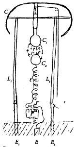
Figure 1 represents diagrammatically the generator which produces stationary waves in the earth, and Fig. 2 an apparatus situated in a remote locality for recording the effects of these waves.
In Fig. 1, A designates a primary coil forming part of a transformer and consisting generally of a few turns of a stout cable of inappreciable resistance, the ends of which are connected to the terminals of a source of powerful electrical oscillations, diagrammatically represented by D. This source is usually a condenser charged to a high potential and discharged in rapid succession through the primary, as in a type of transformer invented by me and now well known; but when it is desired to produce stationary waves of great lengths an alternating dynamo of suitable construction may be used to energize the primary A. . . . the total length of the conductor, from the ground-plate E to the elevated terminal D should be equal to one-quarter of the wave length of the electrical disturbance in the system E C D or else equal to that length multiplied by an odd number. This relation being observed, the terminal D will be made to coincide with the points of maximum pressure in the secondary or excited circuit, and the greatest flow of electricity will take place in the same. In order to magnify the electrical movement in the secondary as much as possible, it is essential that its inductive connection with the primary A should not be very intimate, as in ordinary transformers, but loose, so as to permit free oscillation. . . The spiral form of coil C secures this advantage. The powerful electrical oscillations in the system E C D being communicated to the ground cause corresponding vibrations to be propagated to distant parts of the globe, whence they are reflected and by interference with the outgoing vibrations produce stationary waves the crests and hollows of which lie in parallel circles relatively to which the ground–plate E may be considered to be the pole. Stated otherwise, the terrestrial conductor is thrown into resonance with the oscillations impressed upon it just like a wire. Three requirements seem to be essential to the establishment of the resonating condition.
First. The earth’s diameter passing through the pole should be an odd multiple of the quarter wave length – that is, of the ratio between the velocity of light – and four times the frequency of the currents.
M = D/(1/4 lambda) where lambda = c/f = 4D/M and M is the odd multiple.
C = speed of light at 299,792 km/sec.
D = Earth diameter at 12,742 km.
M = odd multiple at 1
The resonant frequency is therefore given to be: f = M x C / 4D = 5.881965 (Yost)
The resonant frequency based upon round-trip time: f = 2(M x C / 4D) = 11.76393
Second. It is necessary to employ oscillations in which the rate of radiation of energy into space in the form of hertzian or electromagnetic waves is very small . . . say smaller then twenty thousand per second, though shorter waves might be practicable. The lowest frequency would appear to be six per second, in which case there will be but one node, at or near the ground-plate . . .
Third. . . . irrespective of frequency the wave or wave-train should continue for a certain interval of time, estimated to be not less then one-twelfth or probably 0.08484 of a second and which is taken in passing to and returning from the region diametrically opposite the pole . . .
The presence of the stationary waves may be detected in many ways . For instance, a circuit may be connected directly or inductively to the ground and to an elevated terminal and tuned to respond more effectively to the oscillations. Another way is to connect a tuned circuit to the ground at two points lying more or less in a meridian passing through the pole E or, generally stated, to any two points of a different potential.
The specific plan of producing the stationary waves, here-in described, might be departed from. For example, the circuit which impresses the powerful oscillations upon the earth might be connected to the latter at two points [a type-two transmitter].
In collecting the energy of these disturbances in any terrestrial region at a distance from their source, . . . the most economical results will be generally secured by the employment of my synchronized receiving transformer.
To complete this description, it may be stated that when it is desired to operate, independently, a great many receiving devices, by such stationary waves of different length, the principles which I have set forth in my British patent 14,579 [1901] and in my United States patents Nos. 723,188 and 725,605 [1903] may be resorted to for rendering the signals or quantities of energy intended for any particular receiver or receivers non-interfering and non-interferable.
Related statements from Nikola Tesla On His Work With Alternating Currents and Their Application to Wireless Telegraphy, Telephony, and Transmission of Power:
[Quote] To give you an idea, I have prepared a diagram illustrating an analogue which will clearly show how the current passes through the globe. You know that in a solar eclipse the moon comes between the sun and the earth, and that its shadow is projected upon the earth's surface. Evidently, in a given moment, the shadow will just touch at a mathematical point, the earth, assuming it to be a sphere.
Diagram illustrating the mode of propagation of the current from the transmitter over the earth’s surface.
Let us imagine that my transmitter is located at this point, and that the current generated by it now passes through the earth. It does not pass through the earth in the ordinary acceptance of the term, it only penetrates to a certain depth according to the frequency. Most of it goes on the surface, but with frequencies such as I employ, it will dive a few miles below. It can be mathematically shown that it is immaterial how it passes; the aggregate effect of these currents is as if the whole current passes from the transmitter, which I call the pole, to the opposite point, which I call the antipode. [Nikola Tesla On His Work With Alternating Currents and Their Application to Wireless Telegraphy, Telephony, and Transmission of Power, pp. 137-138]
The phrase “a few miles below” gives the earth current propagation model a minimum skin depth of 3 miles, 15,850 feet, or 4,828 meters.
Assume, then, that here is the transmitter, and imagine that this is the surface of the sea, and that now comes the shadow of the moon and touches, on a mathematical point, the calm ocean. You can readily see that as the surface of the water, owing to the enormous radius of the earth, is nearly a plane, that point where the shadow falls will immediately, on the slightest motion of the shadow downward, enlarge the circle at a terrific rate, and it can be shown mathematically that this rate is infinite. In other words, this half-circle on this side will fly over the globe as the shadow goes down; will first start at infinite velocity to enlarge, and then slower and slower and slower, and as the moon's shadow goes further and further and further, it will get slower and slower until, finally, when the three bodies are on the plane of the ecliptic, right in line one with the other in the same plane, then that shadow will pass over the globe with its true velocity in space. Exactly that same thing happens in the application of my system, and I will show this next.
Diagram illustrating the law governing the passage of the current from the transmitter through the earth, first announced in U.S. Patent No. 787,412 of April 18, 1905. Application filed May 16, 1900. See also J. Erskine-Murray, A Handbook of Wireless Telegraphy, Chapt. 17, pp. 312-330, 1913 edition, published by Crosby Lockwood and Son, London, and Appleton & Company, New York.
This illustrates, on a larger scale, the earth. Here is my transmitter -- mine or anybody's transmitter -- because my system is the system of the day. The only difference is in the way I apply it. They, the radio engineers, want to apply my system one way; I want to apply it in another way. This is the circuit energizing the antenna. As the vibratory energy flows, two things happen: There is electromagnetic energy radiated and a current passes into the earth. The first goes out in the form of rays, which have definite properties. These rays propagate with the velocity of light, 300,000 kilometers per second. This energy is exactly like a hot stove. If you will imagine that the cylinder antenna is hot -- and indeed it is heated by the current -- it would radiate out energy of exactly the same kind as it does now. If the system is applied in the sense I want to apply it, this energy is absolutely lost, in all cases most of it is lost. While this electromagnetic energy throbs, a current passes into the globe.
Now, there is a vast difference between these two, the electromagnetic and current energies. That energy which goes out in the form of rays, is, as I have indicated here, unrecoverable, hopelessly lost. You can operate a little instrument by catching a billionth part of it but, except this, all goes out into space never to return. This other energy, however, of the current in the globe, is stored and completely recoverable. Theoretically, it does not take much effort to maintain the earth in electrical vibration. I have, in fact, worked out a plant of 10,000 horse-power which would operate with no bigger loss than 1 percent of the whole power applied; that is, with the exception of the frictional energy that is consumed in the rotation of the engines and the heating of the conductors, I would not lose more than 1 percent. In other words, if I have a 10,000 horsepower plant, it would take only 100 horsepower to keep the earth vibrating so long as there is no energy taken out at any other place.
There is another difference. The electromagnetic energy travels with the speed of light, but see how the current flows. At the first moment, this current propagates exactly like the shadow of the moon at the earth's surface. It starts with infinite velocity from that point, but its speed rapidly diminishes; it flows slower and slower until it reaches the equator, 6,000 miles from the transmitter. At that point, the current flows with the speed of light -- that is, 300,000 kilometers per second. But, if you consider the resultant current through the globe along the axis of symmetry of propagation, the resultant current flows continuously with the same velocity of light.
Whether this current passing through the center of the earth to the opposite side is real, or whether it is merely an effect of these surface currents, makes absolutely no difference. To understand the concept, one must imagine that the current from the transmitter flows straight to the opposite point of the globe.
There is where I answer the attacks which have been made on me. For instance, Dr. Pupin has ridiculed the Tesla system. He says,
"The energy goes only in all directions."
It does not. It goes only in one direction. He is deceived by the size and shape of the earth. Looking at the horizon, he imagines how the currents flow in all directions, but if he would only for a moment think that this earth is like a copper wire and the transmitter on the top of the same, he would immediately realize that the current only flows along the axis of the propagation.
The mode of propagation can be expressed by a very simple mathematical law, which is, the current at any point flows with a velocity proportionate to the cosecant of the angle which a radius from that point includes with the axis of symmetry of wave propagation. At the transmitter, the cosecant is infinite; therefore, the velocity is infinite. At a distance of 6,000 miles, the cosecant is unity; therefore, the velocity is equal to that of light. This law I have expressed in a patent by the statement that the projections of all zones on the axis of symmetry are of the same length, which means, in other words, as is known from rules of trigonometry, that the areas of all the zones must also be equal. It says that although the waves travel with different velocities from point to point, nevertheless each half wave always includes the same area. This is a simple law, not unlike the one which has been expressed by Kepler with reference to the areas swept over by the radii vectors.
I hope that I have been clear in this exposition – in bringing to your attention that what I show here is the system of the day, and is my system -- only the radio engineers use my apparatus to produce too much of this electromagnetic energy here, instead of concentrating all their attention on designing an apparatus which will impress a current upon the earth and not waste the power of the plant in an uneconomical process.
Counsel;
You say radio engineers put too much energy into the radiating part. What, as a matter of fact, according to your conception, is the part of the energy that is received in the receivers in the present system?
Tesla;
That has been investigated. Very valuable experiments have been made by Dr. Austin, who has measured the effects at a distance. He has evolved a formula in agreement with the Hertz wave theory, and the energy collected is an absolutely vanishing quantity. It is just enough to operate a very delicate receiver. If it were not for such devices as are now in use, the audion, for instance, nothing could be done. But with the audion, they magnify so that this infinitesimal energy they get is sufficient to operate the receiver. With my system, I can convey to a distant point millions of times the energy they transmit. [Nikola Tesla On His Work With Alternating Currents and Their Application to Wireless Telegraphy, Telephony, and Transmission of Power, pp. 138-142] [End Quote]
Terrestrial Resonances:
It has been proposed that there are two forms of terrestrial resonance, Schumann resonance and (for lack of a better term) Earth resonance, both related to the diameter of the earth. Schumann resonance is studied by observing the effects of lightning discharges upon the electrical condition of the earth, specifically the naturally occurring electric and magnetic fields. Earth’s electrical condition can also be modified by artificial means, as did Tesla, by use of a properly tuned and configured electrical oscillator. The world’s AC power distribution systems do this more or less continuously, to a limited degree.
Schumann resonance:
Fundamental period of resonant oscillation: shifts between 7.5 - 7.9 Hz. (Anderson, Bradford)
Q: 3 to 12 (Anderson, Bradford), “at least 100” (Sutton, John F. and Craig Spaniol, “A Measurement of the Magnetic Earth-Ionosphere Cavity Resonances in the 3-30 Hz. Range,” Proceedings of the 1988 International Tesla Symposium, Int’l Tesla Society, 1990, pp. 3–17-3–23
Wave description: “cavity wave” (Yost), “surface wave” (Wasser)
Detection: buried 3-component magnetic field sensors & multiple component elevated electric field sensors
Earth resonance:
Fundamental period of resonant oscillation: 11.76393 (Yost), 11.79 Hz. (Wasser) *
Q: [unknown]
Wave description: “electrodynamic wave” (Sommerfeld), “conductor wave” (Yost) “pressure wave” (Wasser),
Detection: buried 3-component magnetic field sensors & buried 3-component electric potential gradient sensors
[*] Fundamental period of resonant oscillation based upon round-trip time.
Some harmonic of the fundamental earth resonant frequency—up to approximately 25 – 35 kHz—is used for the oscillator frequency. In this frequency range the around-the-world propagation efficiency is in the general area between 93 to 87%. As the frequency is increased above this point, efficiency further decreases. At 160 kHz the efficiency falls below 10%. [Corum, K. L. and J. F. Corum, “Nikola Tesla, Lightning Observations and Stationary Waves," Proceedings of the 1994 Colorado Springs Tesla Symposium, 1994, Appendix II, "The Zenneck Surface Wave"] The oscillatory transformer provides the high voltage alternating current needed to periodically charge the transmitter’s elevated terminal. A monochromatic subcarrier signal is then added. This is in the form of an abrupt lower frequency electrical impulse applied at a rate approaching the fundamental earth resonance frequency. Higher frequency impulses, above the oscillator frequency are also added at every harmonic of the low frequency subcarrier impulse, be it the fundamental earth resonance frequency or some lower harmonic of same. [Corum & Corum] While the following quote refers to the use of an RF alternator in conjunction with a resonance transformer to produce continuous waves, it appears to be applicable to the excitation of earth resonance modes as well.
I reduced the number of poles, I think, in 1901. But then I reduced it for the purpose of generating currents of higher frequency. If I had a great number of poles, I could not realize my idea, because these poles would come in quick succession and not produce a rate of change comparable to the rate of change which is obtainable by the discharge of a condenser owing to a sudden break of the dielectric. That is to say, a blow. It has to be a blow, you see. I had to place my poles comparatively far apart, then run them at excessive speed and generate comparatively few impulses, but each of those impulses are of such tremendous intensity that the dynamo is practically short-circuited. That gave me a blow which replaced the arc. And then, of course, there remained to be perfected a scheme enabling me to get the energy of the alternator in the most economical manner, in high harmonics. That is not known, at least I have not seen anything of that kind in literature, and I believe that if anybody would attempt it without the devices which I have invented, he could not get much of the energy in high harmonics. [Nikola Tesla On His Work With Alternating Currents and Their Application to Wireless Telegraphy, Telephony, and Transmission of Power, p. 15]
The system would be composed of two or more type-one transmitter/receiver signal-generating facilities, each contributing energy to the entire network to a greater or lesser degree. The resulting wave complex would be the combination of multiple electrical oscillations ranging from the fundamental earth resonance frequency or some low harmonic thereof, the oscillator frequency, and higher frequency impulses extending, possibly, to the upper limit of the radio frequency spectrum. The elevated terminal acting as an antenna might be capable of directly launching the higher frequency components of the wave complex as electromagnetic radiation, providing localized radio-frequency signal coverage. If true, this might provide an opportunity for locally originated programming that would be associated only with a local source or generator, to the exclusion of other signal-generating facilities operating on the same frequencies.
Operating Frequencies
At Wardenclyffe Tesla operated at frequencies from 1,000 Hz to 100 kHz. He found the frequency range up to 30 – 35 kHz, “to be most economical.” [Nikola Tesla On His Work With Alternating Currents and Their Application to Wireless Telegraphy, Telephony, and Transmission of Power, pp. 143, 155] In operation, the system would have generated and sustained a wave complex . . .
Based upon an analysis of the Colorado Springs Notes and other sources [including Corum & Corum] it appears a basic World System oscillator would develop a wave complex with an extremely low frequency (ELF) component in the 6 – 1000 Hz range [obtained with an alternator, NTAC, p. 155] plus a very low frequency (VLF) component around 25 – 35 kHz. Tesla specified a frequency of 925 Hz for power transmission in the patents “System of Transmission of Electrical Energy,” U.S. Patent No. 645,576, dated March 20, 1900 and “Apparatus for Transmission of Electrical Energy,” U.S. Patent No. 649,621, dated May 15, 1900.
For such a low frequency, to which I shall resort only when it is indispensable to operate motors of the ordinary kind under the conditions above assumed, I would use a secondary of fifty miles in length.
The Telecommunications Transmitting / Receiving Plant
Minimally implemented, a type-one transmission system requires two synchronized type-one electrical oscillators, each consisting of an appropriate radio-frequency power supply connected to the earth and a vertically oriented top-loaded helical resonator. In operation a pulsed electrical potential is applied to each of the two helical resonators creating, at each location, an oscillating magnetic field. In turn, each oscillating magnetic field induces an oscillating electric field. Together the oscillating electric and magnetic fields create weakly to highly ionized plasma in the vicinity of each resonator. [If the two resonators have a 180deg phase relationship with each other they are optimally aligned for connection of their respective magnetic fields.] In addition to the inductively coupled discharge created plasma, conditions also exist for the creation of capacitively coupled discharge plasma between the two respective elevated terminals. This is the “aurora” effect described by Tesla in the 1916 interview.
I have constructed and patented a form of apparatus which, with a moderate elevation of a few hundred feet, can break the air stratum down. You will then see something like an aurora borealis across the sky, and the energy will go to the distant place. [Nikola Tesla On His Work With Alternating Currents and Their Application to Wireless Telegraphy, Telephony, and Transmission of Power, p. 110]
Each plant would be about the size of the Wardenclyffe prototype, with multiple resonators, a fixed elevated terminal and a high-power local oscillator. Each would have very wide bandwidth Internet and telephone network interfaces and be permanently connected with providers of radio and television programming.
The Electrical Power Distribution Plant
A grounded magnifying transmitter probably larger than the Wardenclyffe prototype with fewer resonators, a fixed elevated terminal plus a high-power local oscillator. Located near sources of energy such as large waterfalls, wind farms, solar power plants and developed sources of geothermal energy, also oil fields, coal mines, etc. May be comprised of two type-one transmitters in relatively close proximity to each other, forming a single type-two transmitter.
The Helical Resonator
The helical resonator is involved in making the above-ground portion of the launching structure resonant at the operating frequency but it is not an antenna-loading coil. [Corum & Corum] The coil is also involved in launching of the ‘current wave’, i.e., ground current and associated surface wave; (see Fritz Lowenstein, lecture before the IRE, 1915 (find it), Tesla Primer and Handbook, Ch. 2, Corum & Corum.)
The Elevated Terminal
The elevated terminal of a Tesla transmitter/receiver facility, referred to by some as an “isotropic capacitance,” does not exist in total isolation from the environment; it is coupled to its surroundings. According to the patent SYSTEM FOR TRANSMISSION OF ELECTRICAL ENERGY and Tesla’s article THE TRUE WIRELESS there is an interaction between the elevated terminals of the transmitter and the receiver facilities involving electrostatic induction and, in some cases, true electrical conduction through plasma. In operation the elevated terminal functions as one plate a capacitor. In opposition to the terminal is all other matter in the environment, especially on the earth’s surface, including the receiver’s elevated terminal. The terminal serves two purposes: first, in conjunction with the earth’s surface, especially in the locality of the transmitter, it acts as a charge reservoir. Secondly it is one of two capacitor plates, the other plate being the elevated terminal of the receiving facility, with which it acts in conjunction. In a high-power system they jointly act as a high voltage discharge terminals for the formation of capacitively coupled discharge plasma with interconnection taking place through the upper level atmosphere.
. . . The elevated terminal charged to a high potential induces an equal and opposite charge in the earth and there are thus Q lines giving an average current I = 4Qn which circulates locally and is useless except that it adds to the momentum. A relatively small number of lines q however, go off to great distance and to these corresponds a mean current of Ie = 4qn to which is due the action at a distance. The total average current in the antenna is thus Im = 4Qn + 4qn and its intensity is no criterion for the performance. The electric efficiency of the antenna is q/Q+q and this is often a very small fraction. [“ The True Wireless ” Electrical Experimenter, May 1919]
In operation, a strong electrostatic field is produced around a Tesla transmitter/receiver facility. Field lines extend outward from the elevated terminal to come in contact with other objects in the environment. While more or less a majority of the field lines of a type-one transmitter are associated with nearby objects, some of them, in theory, are associated with the elevated terminal of the other plant.
The Improved Elevated Terminal
The 1914 patent “Apparatus for Transmitting Electrical Energy” refers to an improved elevated or free terminal.
Referring to the accompanying drawing, the figure is a view in elevation and part section of an improved free terminal and circuit of large surface with supporting structure and generating apparatus. . . . A part of the improvements which form the subject of this specification, the transmitting circuit, in its general features, is identical with that described and claimed in my original Patents Nos. 645,576 and 649,621. . . . [Dr. Nikola Tesla Complete Patents, p. 436]
Tesla’s work was directed towards the development of a system that combined wireless telecommunications and electrical power transmission, the communications component being Tesla’s initial goal. While electrical power transmission was viewed as being of greater importance, the attempt at its large-scale implementation would have taken place after the feasibility of the basic concept had been established.
The currents are proportionate to the potentials which are developed under otherwise equal conditions. If you have an antenna of a certain capacity charged to 100,000 volts, you will get a certain current; charged to 200,000 volts, twice the current. When I spoke of these enormous potentials, I was describing an industrial plant on a large scale because that was the most important application of these principles [the wireless transmission of electrical power], but I have also pointed out in my patents that the same principles can be applied to telegraphy and other purposes. That is simply a question of how much power you want to transmit. [Nikola Tesla On His Work With Alternating Currents and Their Application to Wireless Telegraphy, Telephony, and Transmission of Power, p. 145]
When the system as configured for telecommunications purposes only, the potential of each elevated terminal might be relatively low. The energy flow between the elevated terminals is by means of electrostatic induction. [What if the distance between facilities is greater than one wavelength?]
For high power energy transmission by true electrical conduction, a very high potential on the elevated terminal is needed in order to break down the insulating stratum around and above each plant. As the potential is increased a point will eventually be reached at which charge on the terminal will ‘break out’ and form what Tesla called “streamers.” Once this fault situation occurs, the potential drops and the system goes out of tune.
In this experiment, the voltage might have been something like 7 or 8 million volts, but I want to tell you, though, that I am referring to the maximum potential. The moment you get these enormous streamers the potential drops. I mean that was the breaking potential. [Nikola Tesla On His Work With Alternating Currents and Their Application to Wireless Telegraphy, Telephony, and Transmission of Power, p. 112]
The maximum potential can be increased by the prevention of streamers. The 1914 patent shows an improved terminal that achieved this by modifying the terminal’s smooth surface with closely spaced hemispherical attachments.
A further improved terminal wasn’t available until the mid 1930s, at which time the following announcement appeared, “Tesla Prepares to Send Power Without Wires, Inventor, 80, Announces Solution of Problem He Worked on for 35 Years. Earth Will Carry Current. 100-Million-Volt Plant to be Build in Foreign Land," (N. Y. Herald Tribune, July 27, 1936). It was the vacuum tube studded elevated terminal, disclosed in “New Art of Projecting Concentrated Non-Dispersive Energy Through Natural Media,” that freed him to make this statement.
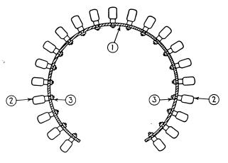
Tesla’s improved terminal, circa 1936, consists of 1) a spherical frame, 2) an insulating bulb with an electrode of thin sheet metal suitably rounded and a metallic socket, exhausted to the highest vacuum obtainable, attached with 3) a nut fastener. [Nikola Tesla’s Teleforce and Telegeodynamics Proposals, p. 22]
The elevated terminal is involved in the launching of a plasma wave, a “disturbance of a plasma away from equilibrium, involving oscillations of the plasma's constituent particles and/or the electromagnetic field.” Propagation of the ion acoustic wave in plasma conforms with Tesla’s description of “the universal medium . . . a gaseous body in which only longitudinal pulses can be propagated, involving alternating compressions and expansions similar to those produced by sound waves in the air. (See THE GENERATION OF PLASMA WAVES AT THE EARTH’S SURFACE . . . ) (This is not to say that plasma is a requirement for the propagation of radio waves.) The high-power pulsed magnetic field produced by the helical-resonator transmitting element may also be involved in the conduction process.
Keeping in mind that plasma is an electrical conductor with finite resistivity, when attempting to simulate the World System, the mathematical model must incorporate a value for the effective resistance between the two elevated terminals as well as earth resistance and that of the ground connections.
The Connection to Earth
In 1916 Tesla described the underground portion of the Wardenclyffe tower in this way,
In this system that I have invented it is necessary for the machine to get a grip of the earth, otherwise it cannot shake the earth. It has to have a grip on the earth so that the whole of this globe can quiver, and to do that it is necessary to carry out a very expensive construction. I had in fact invented special machines. . . . There was a big shaft about ten by twelve feet goes down about one hundred and twenty feet and this was first covered with timber and the inside with steel and in the center of this there was a winding stairs going down and in the center of the stairs there was a big shaft again through which the current was to pass . . . And then the real expensive work was to connect that central part with the earth, and there I had special machines rigged up which would push the iron pipe, one length after another, and I pushed these iron pipes, I think sixteen of them, three hundred feet, and then the current through these pipes takes hold of the earth. Now that was a very expensive part of the work, but it does not show on the tower, but it belongs to the tower. [Nikola Tesla On His Work With Alternating Currents and Their Application to Wireless Telegraphy, Telephony, and Transmission of Power, p. 203]
Tesla System Receivers
Regarding the potential at the receiver’s elevated terminal it is related to the potential at the transmitter’s elevated terminal. As we are speaking of electrical conduction, I2R losses should be applicable in this case. The resistance is that of the intervening plasma between the two elevated terminals and of the earth between the two ground terminals. There is also a voltage divider in that some of the current associated with the elevated terminal passes to ground and back to the transmitter’s ground terminal. This current, “circulates locally and is useless except that it adds to the momentum.” [“ The True Wireless ” Electrical Experimenter, May 1919]
[Switching receiver patent description, charge accumulating capacitor.]
The Wavemeter
This consists of a grounded helical resonator with a widely adjustable elevated terminal and no local oscillator. It may have a small adjustable ferrite core. Incorporates an e-field probe detector with a high impedance amplifier or a few secondary turns with a low impedance amplifier. May incorporate active antenna circuitry (see Regeneration Revisited and John F. Sutton’s U.S. Patent No. 5,296,866, Active antenna (March 22, 1994).
[Abstract: An antenna, which may be a search coil, connected to an active circuit which provides negative impedances, each of which is of the order of magnitude of the positive impedances which characterize this active antenna. In one embodiment, one coil terminal is connected to an amplifier which drives a voltage-controlled current source that, in turn, drives a feedback coil which is coupled to the original search coil. In another embodiment that additionally exhibits an advantageous signal-to-noise characteristic, both terminals of the search coil are connected to a differential amplifier that, in turn, provides the control voltage for a current source, which, as in the first embodiment, drives the feedback winding. The feedback coil is wound to provide positive feedback by additive superposition of both coil fields. The positive feedback provided by the feedback current lowers the antenna impedance which, in turn, increases the effective area of the antenna. This circuit configuration incorporates a differentiation inherent in the fundamental characteristic of a coil, which is sensitive to the rate-of-change of the magnetic field. The outstanding stability of this active antenna may be attributed to the inherent accuracy of this differentiation performed by the antenna coil, to the particular circuit configurations and to the particular form of feedback employed.]
The Dedicated or Domestic Receiver
A grounded resonator with an adjustable elevated terminal plus a low-power local oscillator. Uses an e-field probe detector, or a secondary winding for drawing off small amounts of power.
The Electrical Power Distribution Plant Substation
A grounded magnifying transmitter perhaps larger than the Wardenclyffe prototype with fewer resonators, a fixed elevated terminal plus a medium-to-high-power local oscillator. Is linked to wired power distribution grid.
The Evolution of Tesla’s Air-Ground System for Wireless Energy Transmission
The air-ground system evolved from Tesla’s one-wire method of energy transmission over a circuit that was not closed “in the ordinary acceptance of the term.” While there is no physically solid second conductor connected back to the generator, the capacitor plates at both ends of the “one-wire” circuit couple to its counterpart or opposite member directly or through ground, depending upon the distance between the two terminals, thus constituting the return circuit.
This, as well as the description “air-ground method” implies that the system depends upon the existence of a connection between the elevated terminals. Additional support to this assertion is found in the Electrical Transformer patent covering the Tesla coil, which describes electrical power transmission through a single wire with ground for return.
Tesla’s 1897 patent drawing showing the transmission of electrical energy through one wire with ground for return.
Also, the apparatus used in the 1898 Patent Office demonstration at the Houston St. lab involved the transmission of electrical energy in industrial amounts through a rarified medium with ground for return.
Tesla’s diagram representing the arrangement of apparatus as demonstrated to U.S. patent examiner G.D. Seeley in the Houston Street laboratory. This showed the transmission of electrical energy through a rarefied atmosphere with ground for return.
Tesla’s 1900 patent drawing showing a system for the wireless transmission and reception of electrical energy through the earth’s rarefied upper atmosphere with ground for return. [Transmitter type-one, C/S #1]
My experiments . . . in Colorado showed that at a height of 1 mile it is plenty enough rarefied to break down under the stress and conduct the current to the distant points. . . . My patent says that I break down the atmosphere "at or near" the terminal. If my conducting atmosphere is 2 or 3 miles above the plant, I consider this very near the terminal as compared to the distance of my receiving terminal, which may be across the Pacific. . . . I have constructed and patented a form of apparatus which, with a moderate elevation of a few hundred feet, can break the air stratum down. You will then see something like an aurora borealis across the sky, and the energy will go to the distant place. . . . An apparatus which permits displacing a certain quantity of electricity in the terminal—we shall say so many units—will produce an electric potential at a distance of 5 miles, and the fall of electric potential per centimeter will be equal to the quantity of electricity divided by the square of the distance. . . . Now, I have satisfied myself that I can construct plants in which I may produce, per kilometer of the atmosphere, electric differences of potential of something like 50,000 or 60,000 volts, and at 50,000 or 60,000 volts that atmosphere must break down and will become conductive. [NTAC]
Furthermore, Tesla made the following statement regarding his theory and technique of energy transmission.
The earth is 4,000 miles radius. Around this conducting earth is an atmosphere. The earth is a conductor; the atmosphere above is a conductor, only there is a little stratum between the conducting atmosphere and the conducting earth which is insulating. . . . Now, you realize right away that if you set up differences of potential at one point, say, you will create in the media corresponding fluctuations of potential. But, since the distance from the earth's surface to the conducting atmosphere is minute, as compared with the distance of the receiver at 4,000 miles, say, you can readily see that the energy cannot travel along this curve and get there, but will be immediately transformed into conduction currents, and these currents will travel like currents over a wire with a return. The energy will be recovered in the circuit, not by a beam that passes along this curve and is reflected and absorbed, . . . but it will travel by conduction and will be recovered in this way. [NTAC]
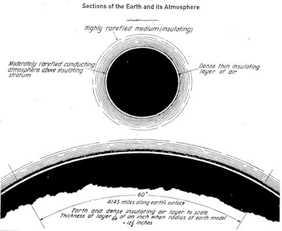
Tesla’s diagram explanatory of the transmission of electrical energy by the ground air method. This was first put before Lord Kelvin in the Houston Street laboratory in September 1897.
It should be noted that in describing the “atmosphere above” as being conducting he roughly predicted the existence of the ionosphere and the earth-ionosphere cavity.
Appendix
The Type-one verses the Type-two Transmitter
The question arises as to the cause of the failure reported the 1903 letter to J.B. Morgan. Is the two-coil/two ground concept fundamentally flawed, or was the problem in its’ single-tower implementation? It’s possible the earlier type-two transmitter tests were performed using plant’s chimney-mounted lightning protector as an elevated capacitance in conjunction with the laboratory-side pancake coil, aka the New York oscillator. In this case the tower-side transmitting element would have been a passive extra-coil helical resonator connected to the tower’s cupola and grounding structure. This would have represented a true type-two transmitter, however the amount of power that could have been processed by the alternator-driven oscillator would have been limited by its’ relatively small size.
In the 1925 paper “Wireless power system using the surface of the earth as a conductor,” John B Flowers, H.L. Curtis, J.H. Dillinger, Radio Laboratory, Bureau of Standards, Washington, D.C. [Harnessing the Wheelwork of Nature, pp. 22-23] a statement is made regarding the feasibility of using 60 cycles-per-second as the systems fundamental frequency. An electric generator is connected with wires to ground points 750 miles apart. Although not a true Tesla wireless apparatus, the design does suggest a type-two transmitter.]
In 1932 journalist J.J. O’Neill conducted an interview with Tesla in which he makes a distinction between the transmission of electrical energy by atmospheric conduction and earth resonance principles.
I also asked him if he is still at work on the project which he inaugurated in the '90's of transmitting power wirelessly anywhere on earth. He is at work on it, he said, and it could be put into operation. . . . He at that time announced two principles which could be used in this project. In one the ionizing of the upper air would make it as good a conductor of electricity as a metal [using a type-one transmitter]. In the other the power would be transmitted by creating "standing waves" in the earth by charging the earth with a giant electrical oscillator [of the type-two design] that would make the earth vibrate electrically in the same way a bell vibrates mechanically when it is struck with a hammer. "I do not use the plan involving the conductivity of the upper strata of the air," he said, "but I use the conductivity of the earth itself, and in this I need no wires to send electrical energy to any part of the globe." [“Tesla Cosmic Ray Motor May Transmit Power 'Round’ Earth,” Brooklyn Eagle , July 10, 1932, John J. A. O'Neill ]
In 1934 the following drawing of a large type-two transmitter appeared in an article on wireless power transmission.
The caption reads, “Nikola Tesla, electrical wizard, foresees the day when airplanes will be operated by radio-transmitted power supplied by ground stations, as shown . . .” [Transmitter type-two, C/S #6; "Radio Power Will Revolutionize the World," Modern Mechanix and Inventions, July 1934, Tesla Said, pp. 261-266]
This suggests that the problem was, in fact, the single-tower implementation, and at some point prior to 1932 Tesla validated the type-two launching structure configuration using two properly spaced top-loaded helical resonators.
One additional observation needs to be made before leaving the subject of the initial Wardenclyffe circuit configuration. Some descriptions of the Wardenclyffe tower include a vertical conductor extending from the bottom of the 120 shaft below the tower up to the under side of the cupola. One account states,
Excitation currents pulsed through a 16-section telescoping shaft that rose under air pressure 300 feet from the bottom of the well to contact the spherical terminal. . . . [Anderson, 1969]
and another,
Radio station on Long Island consisted of a large building . . . and a special antenna tower suspended on a wooden pyramid of several meters in diameter with a changeable height position by means of a metal tube which was telescopically vertically moveable, was emerging from a cylindrical 30 m deep hole in the ground beneath the pyramid. . . . [Popovic, 1976]
A direct electrical connection between the elevated isotropic capacitance and the subterranean ground connection would be consistent with the type-two transmitter design. Note that the as-built tower legs were made of wood—not metal—necessitating the conducting shaft. Also, placement of the ground connection at the bottom of the 120-foot excavation might have been a way to partially compensate for height lost in the initial design changes. Tesla’s original plans called for an overall tower height of 600 feet.
Relative Transmission Efficiency, Tesla vs. Marconi Systems
Based upon Tesla’s own descriptions as well as theoretical considerations it should be simple matter to discriminate between the effects created at a distance by a high-power Marconi-type Hertz-wave radio transmitter and those produced by a Tesla type-one transmitter of equivalent power. One would expect the space waves arriving from a Hertz-wave transmitter to generally conform to the well-known inverse-square power relationship defined in radio propagation theory. If Tesla’s claims are correct, the throughput energy of a full-scale type-one Tesla transmitter-receiver pair should exceed that of a Hertz-wave radio system by more than six orders of magnitude.
Counsel;
You say radio engineers put too much energy into the radiating part. What, as a matter of fact, according to your conception, is the part of the energy that is received in the receivers in the present system?
Tesla;
That has been investigated. Very valuable experiments have been made by Dr. Austin, who has measured the effects at a distance. He has evolved a formula in agreement with the Hertz wave theory, and the energy collected is an absolutely vanishing quantity. It is just enough to operate a very delicate receiver. If it were not for such devices as are now in use, the audion, for instance, nothing could be done. But with the audion, they magnify so that this infinitesimal energy they get is sufficient to operate the receiver. With my system, I can convey to a distant point millions of times the energy they transmit. [ntac, pp. 141-142]
Tesla surely made real-world physical measurements in support of this statement.
At present it may be sufficient, for the guidance of experts, to state that the waste of energy is proportional to the product of the square of the electric density induced by the transmitter at the earth's surface and the frequency of the currents. Expressed in this manner it may not appear of very great practical significance. But remembering that the surface density increases with the frequency it may also be stated that the loss is proportional to the cube of the frequency. With waves 300 meters in length economic transmission of energy is out of the question, the loss being too great. When using wave-lengths of 6,000 meters it is still noticeable though not a serious drawback. With wave-lengths of 12,000 meters it becomes quite insignificant and on this fortunate fact rests the future of wireless transmission of energy. [Electrical Review and Western Electrician, July 6, 1912]
The conventional radio surface wave, i.e., the Norton Surface Wave, is the result of electrical currents induced in the ground by refraction of a portion of the reflected-wave component of the ground-wave at the earth-atmosphere interface. In contrast, the surface wave associated with Tesla’s World System is the result of electrical ground currents flowing between two discrete points on the earth’s surface. Unlike the ground-hugging surface-wave component of the space wave that is excited by a conventional radio transmitter, and while not yet verified by mathematical modeling and subsequent physical verification, Tesla’s surface wave would not be expected to diminish as significantly as the distance from the source facility increases (see Rediscovering the Zenneck Surface Wave).
It is indispensable to first dispel a few errors under which electricians have labored for years, owing to the tremendous momentum imparted to the scientific mind through the work of Hertz which has hampered independent thought and experiment. To facilitate understanding, attention is called to the annexed diagrams in which Fig. 1 and Fig. 2 represent, respectively, the well known arrangements of circuits in the Hertz-wave system and my own. In the former the transmitting and receiving conductors are separated from the ground through spark gaps, choking coils, and high resistances. This is necessary, as a ground connection greatly reduces the intensity of the radiation by cutting off half of the oscillator and also by increasing the length of the waves from 40 to 100 percent, according to the distribution of capacity and inductance. In the system devised by me a connection to earth, either directly or through a condenser is essential. The receiver, in the first case, is affected only by rays transmitted through the air, conduction being excluded; in the latter instance there is no appreciable radiation and the receiver is energized through the earth while an equivalent electrical displacement occurs in the atmosphere. [Nikola Tesla, Electrical Review and Western Electrician, July 6, 1912]
Loss Mechanism
In regards to the World System, it is certain there would be radio waves associated with the propagating earth currents. Tesla recognized this phenomenon, stating that the resulting electromagnetic radiation constitutes a mechanism for the loss of energy from the system.
The attractive feature of this plan was that the intensity of the signals should diminish very little with the distance, and, in fact, should not diminish at all, if it were not for certain losses occurring, chiefly in the atmosphere. [“Tesla Describes His Efforts in Various Fields of Work,” Electrical Review - N. Y., Nov, 30, 1898]
Achieving Satisfactory Explanations of the Two Tesla Systems:
The Investigation of Tesla-Type Wireless Propagation [Mathematical modeling and physical validation]
Tesla spent a lifetime trying to explain how his systems work with only minimal use of mathematics. He felt the physical model for the propagation of electromagnetic waves, i.e., “radio waves” developed by Hertz was inadequate for the task.
It was a perfectly well established fact that a circuit, traversed by a periodic current, emitted some kind of space waves, but we were in ignorance as to their character. He [Hertz] apparently gave an experimental proof that they were transversal vibrations in the ether. Most people look upon this as his great accomplishment. To my mind it seems that his immortal merit was not so much in this as in the focusing of the investigators' attention on the processes taking place in the ambient medium. The Hertz-wave theory, by its fascinating hold on the imagination, has stifled creative effort in the wireless art and retarded it for twenty-five years. But, on the other hand, it is impossible to over-estimate the beneficial effects of the powerful stimulus it has given in many directions. [Electrical Experimenter, May 1919]
The best way to find out if the Tesla systems work as he said they do is to repeat the original experiments, that is to say, reproduce the appropriate apparatus and collect the data. The first step might be to adopt the existing models that accurately describe the operation of conventional low-frequency Hertz-wave wireless systems. These could be used as a starting point from which to create models of the Tesla systems using the mathematics of electromagnetism in combination with the academic discipline of magnetohydrodynamics (MHD). MHD studies the dynamics of electrically-conducting fluids, such as plasma, and their interactions with magnetic fields. MHD theory is relevant at relatively low frequencies and for distance scales larger than the Larmor radius. The equations describing MHD are a combination of the Navier-Stokes equations of fluid dynamics and Maxwell's equations of electromagnetism. [Source: Wikipedia see also Plasma Dictionary]
Maxwells Equations express how electric charges produce electric fields (Gauss's law) and how changing magnetic fields produce electric fields (Faraday's law of induction). They also explain how electrical currents produce magnetic fields and the experimental absence of magnetic charges (Ampère's law). The Navier-Stokes equations are a set of nonlinear partial differential equations that describe the flow of fluids such as liquids and gases. These differential equations have to be solved for simultaneously. This is too complex or impossible to do symbolically in all but the most trivial cases. For real-world problems, numeric solutions are found using supercomputers. [Source:
Wikipedia]
Tesla's Magnifying Transmitter:
Wardneclyffe Station,
 The Factual History -
In 1901, Tesla purchased 200 acres on Long Island's north shore from James Warden. These 200 acres were part of an 1,800 acre potato farm along what is today Route 25A in Shoreham, NY.
The site became known as Wardenclyffe, after the former owner. Here, Tesla established what would become his only remaining laboratory building.
Previously, after emigrating to the United States in 1884, Tesla had worked on all of his major projects at various laboratory sites. These included Pittsburgh, PA; New York City, NY; Orange, NJ; Colorado Springs, CO; and finally Wardenclyffe, NY.
In April, 1901, the Wardenclyffe Post Office was established in the town; in l906 the town became the Village of Shoreham. 
The purpose of the Wardenclyffe laboratory was the establishment of a wireless telegraphy plant.
The prestigious architectural firm of McKin, Mead, and White was contracted to design the laboratory and transmitter tower (187 feet high above ground and 120 feet deep below ground level). Stanford White became the architect for the buding.
Tesla's plan had the initial backing of the financier J.P. Morgan. The red brick laboratory building can still be seen on the north side of Route 25A between the intersection of Randall Road and the Shoreham Fire Department.
I have just visited the site, as of May 15th, 2008, and it is still stunning to visualize what happened on this very ground. I stand in awe at Tesla's achievements over one hundred years ago. More on directions for visiting the site on a later page...
During the last week of July 1903, residents around the Shoreham site experienced what was to be the only testing of Tesla's equipment at this facility. Note that Tesla had Wardenclyffe Station OPERATIONAL. After these tests, Tesla NEVER went back. Why???
Several days after these tests, his dream was destroyed when creditors from Westinghouse confiscated his heavier equipment for nonpayment for services rendered.
In addition, James Warden sued Tesla for nonpayment of back taxes. In 1917, the 187-foot tower was destroyed by dynamite explosion as ordered by the U.S. government. It was demolished the same year by the Smiley Steel Company.
In 1939, the Peerless Photo Compa ny purchased the property to manufacture emulsions for photographic film and paper. Additional buildings were constructed. In 1969, it became Agfa-Gevaert, Inc., at that time a division of the Bayer Corporation.
In 1987, manufacturing ended, and the facility was closed down.
Since then, the entire facility has remained dormant. It is noteworthy that, in 1967, the laboratory building was the first to be listed on the Town of Brookhaven registry of historic sites.
Lots more information coming on Tesla's Wardenclyffe Station, and the Magnifying Transmitter.
NEXT (Nikola Tesla page 3)