
Notes and considerations using an Arduino for the WFC Replication project.
The following are inputs/outputs when we would want to make a closed system whereby the exhaust is looped back to the inlet. I don't know if that is feasible, but for the considerations on computer control it might be nice to keep such an option open.
Inputs to measure:
Must have:
- pressure electrolyzer - A
- hall sensor exhaust valve - D
- hall sensor ignition - D
- ignition retard / delay, A (potmeter) or D (buttons)
Should have:
- fluid level electrolyzer
- fluid level mist generator
- fluid level tank
Nice to have:
- pressure inlet - A
- pressure exhaust - A
Must have: 1 analog input and 2 digitale inputs
To control:
Must have:
- ignition - D
- electrolyzer on/off - D
- gas injector inlet - D
Should have:
- pump or valve to electrolyzer - D
- pump or valve to mist generator - D
- liquid injector mist generator - D
Nice to have:
- puls frequency "gate" electrolyzer
- gas injector uitlaat -> inlet
- gas injector lucht inlet
- gas injector exhaust pressure release
Must have: 3 digitale uitgangen Should have: 6 digitale uitgangen
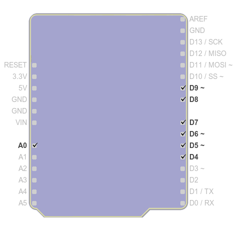
Arduino pinout
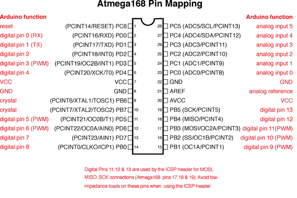
Source: http://arduino.cc/en/Hacking/PinMapping168
Current hardware
I have two Arduino boards, both of which are based on the ATmega168:
| ATmega168 (used on most Arduino Diecimila and early Duemilanove) | |
|---|---|
| Digital I/O Pins | 14 (of which 6 provide PWM output) |
| Analog Input Pins | 6 (DIP) or 8 (SMD) |
| DC Current per I/O Pin | 40 mA |
| Flash Memory | 16 KB |
| SRAM | 1 KB |
| EEPROM | 512 bytes |
Seeeduino v2.21
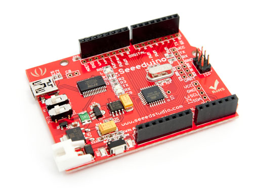
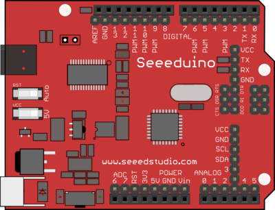
This one has an SMD processor, which has two additional analog inputs, as mentioned in the reference:
Freeduino v 1.16
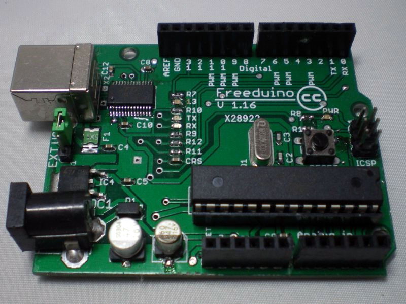
This one has a DIP processor, without the extra two analog inputs.
Nu Electronics LCD Shield
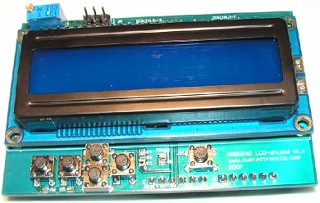
Maker: Nu Electronics
Includes a 16x2 HD44780 compatible LCD, white character & blue backlight. Use Arudino LCD4Bit library. Joystick style Keypad with 5 pushbuttons, but only use one ADC pin on Arduino.
LCD shield uses:
- 7 digital I/O, of which 4 PWM
- 1 Analog input
Left:
- 7 digital I/O, of which 2 PWM
- 7 analog inputs.
Sample code: http://www.dfrobot.com/wiki/index.php?title=Arduino_LCD_KeyPad_Shield_%28SKU:_DFR0009%29
Zie ook: http://en.wikipedia.org/wiki/List_of_Arduino_boards_and_compatible_systems
http://www.seeedstudio.com/wiki/Seeeduino_v2.21 Seeeduino v2.21 (Atmega 168P)
Mine has an ATMega 168 20AU
The Seeeduino has a double row of connectors, one of which is free and can thus be soldered, etc.
http://www.seeedstudio.com/blog/tag/freeduino/
Seeeduino is Arduino compatible board. Its design is based on Diecimila scheme, 100% compatible to its existing program, shield and IDEs. On the hardware part, remarkable changes are taken to improve the flexibility and user experience.
Microcontroller ATmega168 Operating Voltage 5V/3.3V Input Voltage (recommended) 7-12 V Input Voltage (limits) 6-20 V Digital I/O Pins 14 (of which 6 provide PWM output) Analog Input Pins 8 DC Current per I/O Pin 40 mA DC Current for 3.3V Pin 50 mA Flash Memory 16 KB (of which 2 KB used by bootloader) SRAM 1 KB EEPROM 512 bytes Clock Speed 16 MHz
freeduino v1.16
http://mcukits.com/2009/03/12/assembling-the-freeduino-board-kit/ ATmega328 MCU (ATmega168 on older boards).
Mine has a ATmega 168-20
LCD shield
Analog 0 Button (select, up, right, down and left) Digital 4 DB4 Digital 5 DB5 Digital 6 DB6 Digital 7 DB7 Digital 8 RS (Data or Signal Display Selection) Digital 9 Enable Digital 10 Backlit Control
Motor shield is wschl interessant:
http://arduino.cc/en/Main/ArduinoMotorShieldR3
Functionpins per Ch. A pins per Ch. B Direction D12 D13 PWM D3 D11 Brake D9 D8 Current Sensing A0 A1
If you don't need the Brake and the Current Sensing and you also need more pins for your application you can disable this features by cutting the respective jumpers on the back side of the shield.
The additional sockets on the shield are described as follow:
Screw terminal to connect the motors and their power supply. 2 TinkerKit connectors for two Analog Inputs (in white), connected to A2 and A3. 2 TinkerKit connectors for two Aanlog Outputs (in orange in the middle), connected to PWM outputs on pins D5 and D6. 2 TinkerKit connectors for the TWI interface (in white with 4 pins), one for input and the other one for output.
http://www.conrad.nl/ce/nl/product/095061/
Arduino Tinkerkit sensor shield module
Beschrijving
Met de "TinkerKit Sensor Shield" sluit u gemakkelijk TinkerKit sensoren en schakelaars aan. Geen breadboard of soldeerpunten nodig, de 3-draads TinkerKit kabels zijn voldoende om de verschillende sensors en schakelaars uit de TinkerKit-serie te voeden en te gebruiken. Het shield is voorzien van 12 aansluitingen, 3 aansluitpunten voor TinkerKit randapparatuur. De 6 aansluitingen met nummers I0 tot I5 zijn analoge ingangen en de 6 aansluitingen O0 tot 05 zijn analoge uitgangen op pinnen waarmee u PWM-uitgangen voor de Arduino kunt maken. U kunt de toewijzing van de uitgangsaansluitingen O0 tot 05 wijzigen naar digitale ingangen om de sensoren voor alles of niets-waarden te gebruiken (hoge of lage stand), maar niet voor sensoren die puur analoog zijn. Een groene LED geeft de juiste werking van de shield aan en u reset de Arduino-kaart met een drukknop. Daarnaast is de kaart voorzien van een TWI 4-puntsaansluiting zodat u er een randapparaat met I2C-verbinding op kunt aansluiten. De aansluiting levert een voeding van 5V en gebruikt de analoge pinnen 4 en 5 voor de i2C-interface. Het gebruik van de TWI-verbinding gaat dus ten koste van de analoge ingangen 4 en 5. Een 4-punts serieelstekker verzorgt de seri�le aansluiting van andere randapparatuur en is ook voorzien van een 5V voeding. Dit gaat ten koste van de standaard serieverbinding van de Arduino. De twee bevestigingsgaten op de TinkerKit Sensor Shield maken bevestiging op de Arduino-kaart mogelijk. Het derde gat laat u de status van de L13-led van de Arduino zien.
Uitvoering
De mapping van de pinnen op de Arduino ziet er als volgt uit: Pin 11 op de Arduino is bekabeld op O0 op het shield - Pin 10 op de Arduino is bekabeld op O1 op het shield - Pin 9 op de Arduino is bekabeld op O2 op het shield - Pin 6 op de Arduino is bekabeld op O3 op het shield - Pin 5 op de Arduino is bekabeld op O4 op het shield Pin 3 op de Arduino is bekabeld op O5 op het shield.
Arduino I/O Shield Velleman KA05
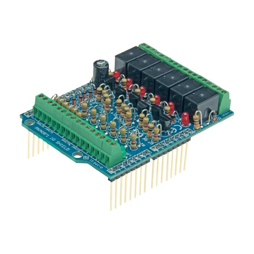
Documentation: pdf
General purpose INPUT - OUTPUT shield for Arduino�
Features
- For use with Arduino Due�, Arduino Uno�, Arduino Mega�
- 6 analog inputs
- 6 digital input
- 6 relay contact outputs
- Indicator leds for relay outputs and digital inputs
Specifications
- Analog inputs: 0..+5VDC
- Digital inputs: dry contact or open collector
- Relays: 12V
- Relay contacts: NO/NC 24VDC/1A max.
- Dimensions: 68 x 53mm / 2.67 x 2.08�
The relay outputs on this board are wired like this:
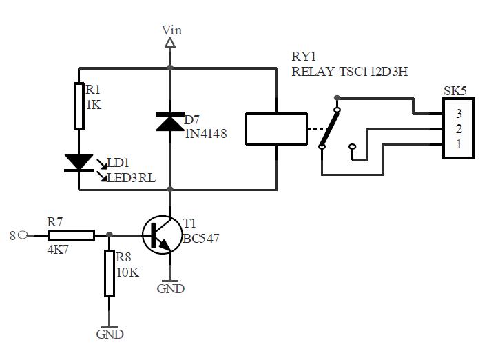
This can be easily converted to an open collector output or a digital output by replacing the diode with a pull up resistor.
The led output can also be used to drive a mosfet trough an optocoupler like this:
And of course one can also drive an ignition coil with a MOSFET, when we protect the MOSFET with a diode. Something like this:
Serial communication
http://arduino.cc/en/reference/serial -:- Used for communication between the Arduino board and a computer or other devices. All Arduino boards have at least one serial port (also known as a UART or USART): Serial. It communicates on digital pins 0 (RX) and 1 (TX) as well as with the computer via USB. Thus, if you use these functions, you cannot also use pins 0 and 1 for digital input or output. -:-
Pin use overview
From the Board reference:
Digital Pins
In addition to the specific functions listed below, the digital pins on an Arduino board can be used for general purpose input and output via the pinMode(), digitalRead(), and digitalWrite() commands. Each pin has an internal pull-up resistor which can be turned on and off using digitalWrite() (w/ a value of HIGH or LOW, respectively) when the pin is configured as an input. The maximum current per pin is 40 mA.
- Serial: 0 (RX) and 1 (TX). Used to receive (RX) and transmit (TX) TTL serial data. On the Arduino Diecimila, these pins are connected to the corresponding pins of the FTDI USB-to-TTL Serial chip. On the Arduino BT, they are connected to the corresponding pins of the WT11 Bluetooth module. On the Arduino Mini and LilyPad Arduino, they are intended for use with an external TTL serial module (e.g. the Mini-USB Adapter).
- External Interrupts: 2 and 3. These pins can be configured to trigger an interrupt on a low value, a rising or falling edge, or a change in value. See the attachInterrupt() function for details.
- PWM: 3, 5, 6, 9, 10, and 11. Provide 8-bit PWM output with the analogWrite() function. On boards with an ATmega8, PWM output is available only on pins 9, 10, and 11.
Analog Pins
In addition to the specific functions listed below, the analog input pins support 10-bit analog-to-digital conversion (ADC) using the analogRead() function. Most of the analog inputs can also be used as digital [input] pins: analog input 0 as digital pin 14 through analog input 5 as digital pin 19. Analog inputs 6 and 7 (present on the Mini and BT) cannot be used as digital pins.
Pin use plan
| Pinout | LCD Shield | Velleman | Tinkerkit | Use | With 2nd Arduino |
|---|---|---|---|---|---|
| DI/O_0 (rx) | serial | ||||
| DI/O_1 (tx) | serial | ||||
| DI/O_2 (ir) | DI1 | exhaust hall sensor | |||
| DI/O_3 (PWM,ir) | DI2 | O5 | ignition hall sensor | ||
| DI/O_4 (T0I) | X | DI3 | |||
| DI/O_5 (PWM,T1I) | X | DI4 | O4 | ||
| DI/O_6 (PWM) | X | DI5 | O3 | ||
| DI/O_7 | X | DI6 | |||
| DI/O_8 | X | RY1 | vacuum relief gas injector | ||
| DI/O_9 (PWM) | X | RY2 | O2 | liquid mist injector | |
| DI/O_10(PWM) | RY3 | O1 | water pump cell / gas injector loopback | ||
| DI/O_11(PWM) | RY4 | O0 | cell on/off | ||
| DI/O_12 | RY5 | ignition trigger | water pump mist | ||
| DI/O_13 | RY6 | gas injector inlet | |||
| AI_0 / DI_14 | X | AI1 | I0 | buttons (ignition ctrl) | |
| AI_1 / DI_15 | AI2 | I1 | cell pressure sensor | ||
| AI_2 / DI_16 | AI3 | I2 | inlet pressure sensor / fluid level mist gen | ||
| AI_3 / DI_17 | AI4 | I3 | exhaust pressure sensor / fluid level main | ||
| AI_4 / DI_18 | AI5 | I4 | fluid level cell | ||
| AI_5 / DI_19 | AI6 | I5 | potmeter ignition ctrl | ||
| AI_6 (SMD) | |||||
| AI_7 (SMD) | |||||
- AI = analog in
- DI = digitial in
- DI/O = digital input or output
- ir : external interrupt.
- SMD: only on SMD type boards.
Timer 1 controls digital I/O Pin 9 and 10. Timer 2 controls digital I/O Pin 3 and 11. Avoid using these.
Programming
Saving settings
Settings can be saved in the internal EEPROM in the processor, in my case 512 bytes.
See:
http://playground.arduino.cc/Code/EEPROMLoadAndSaveSettings
    CONFIG_VERSION must be unique between different sketches;
    Also change it if you do any changes to the "StoreStruct" struct, or you will be in trouble!
There are a number of versions at the source, but the version with the EEPROMex library appears to be the most attractive:
#include <EEPROMex.h>

// ID of the settings block
#define CONFIG_VERSION "ls1"

// Tell it where to store your config data in EEPROM
#define memoryBase 32

bool ok  = true;
int configAdress=0;

// Example settings structure
struct StoreStruct {
    char version[4];   // This is for mere detection if they are your settings
    int a, b;          // The variables of your settings
    char c;
    long d;
    float e[6];
} storage = {
    CONFIG_VERSION,
    220, 1884,
    'c',
    10000,
    {4.5, 5.5, 7, 8.5, 10, 12}
};

void setup() {
  EEPROM.setMemPool(memoryBase, EEPROMSizeUno); //Set memorypool base to 32, assume Arduino Uno board
  configAdress  = EEPROM.getAddress(sizeof(StoreStruct)); // Size of config object
  ok = loadConfig();
}

void loop() {
  // [...]
  int i = storage.c - 'a';
  // [...]
  storage.c = 'a';
  if (ok)
    saveConfig();
  // [...]
}

bool loadConfig() {
  EEPROM.readBlock(configAdress, storage);
  return (storage.version == CONFIG_VERSION);
}

void saveConfig() {
   EEPROM.writeBlock(configAdress, storage);
}
The library by default has a #define for debugging and thus prevents more than 100 writes.
http://thijs.elenbaas.net/2012/07/extended-eeprom-library-for-arduino/
Copy: http://www.tuks.nl/WFCProject/var/Arduino/downloads/EEPROMEx.0.8.3.zip
Serial communication / debugging
http://www.ladyada.net/learn/arduino/lesson4.html
Interrupts
http://arduino.cc/en/Reference/Volatile
volatile is a keyword known as a variable qualifier, it is usually used before the datatype of a variable, to modify the way in which the compiler and subsequent program treats the variable.
Declaring a variable volatile is a directive to the compiler. The compiler is software which translates your C/C++ code into the machine code, which are the real instructions for the Atmega chip in the Arduino.
Specifically, it directs the compiler to load the variable from RAM and not from a storage register, which is a temporary memory location where program variables are stored and manipulated. Under certain conditions, the value for a variable stored in registers can be inaccurate.
A variable should be declared volatile whenever its value can be changed by something beyond the control of the code section in which it appears, such as a concurrently executing thread. In the Arduino, the only place that this is likely to occur is in sections of code associated with interrupts, called an interrupt service routine.
Overhead
http://billgrundmann.wordpress.com/2009/03/02/the-overhead-of-arduino-interrupts/
Notice that the total period for the LED is 26.60usec. That means the off time for the LED is 23.165usec, which is 3.165usec longer than the delay statement request. Let�s now look at what happens under the hood.
It may be worth addressing the ports/pins of the ATMEL chip directly instead of using the digitalWrite() and digitalRead() functions: http://www.arduino.cc/en/Reference/PortManipulation
Avaiable interrupts
http://gammon.com.au/interrupts
http://www.gammon.com.au/forum/?id=11488
 1  Reset
 2  External Interrupt Request 0  (pin D2)          (INT0_vect)
 3  External Interrupt Request 1  (pin D3)          (INT1_vect)
 4  Pin Change Interrupt Request 0 (pins D8 to D13) (PCINT0_vect)
 5  Pin Change Interrupt Request 1 (pins A0 to A5)  (PCINT1_vect)
 6  Pin Change Interrupt Request 2 (pins D0 to D7)  (PCINT2_vect)
 7  Watchdog Time-out Interrupt                     (WDT_vect)
 8  Timer/Counter2 Compare Match A                  (TIMER2_COMPA_vect)
 9  Timer/Counter2 Compare Match B                  (TIMER2_COMPB_vect)
10  Timer/Counter2 Overflow                         (TIMER2_OVF_vect)
11  Timer/Counter1 Capture Event                    (TIMER1_CAPT_vect)
12  Timer/Counter1 Compare Match A                  (TIMER1_COMPA_vect)
13  Timer/Counter1 Compare Match B                  (TIMER1_COMPB_vect)
14  Timer/Counter1 Overflow                         (TIMER1_OVF_vect)
15  Timer/Counter0 Compare Match A                  (TIMER0_COMPA_vect)
16  Timer/Counter0 Compare Match B                  (TIMER0_COMPB_vect)
17  Timer/Counter0 Overflow                         (TIMER0_OVF_vect)
18  SPI Serial Transfer Complete                    (SPI_STC_vect)
19  USART Rx Complete                               (USART_RX_vect)
20  USART, Data Register Empty                      (USART_UDRE_vect)
21  USART, Tx Complete                              (USART_TX_vect)
22  ADC Conversion Complete                         (ADC_vect)
23  EEPROM Ready                                    (EE_READY_vect)
24  Analog Comparator                               (ANALOG_COMP_vect)
25  2-wire Serial Interface  (I2C)                  (TWI_vect)
26  Store Program Memory Ready                      (SPM_READY_vect)
This also includes an example for firing sparks for an ignition system:
http://www.tuks.nl/WFCProject/var/Arduino/Spark_firing_timer_ISR_example/
How long does it take to execute an ISR?
http://gammon.com.au/interrupts
[...]
[...]
[...]
When I count correctly, I count 47 cycles for entering and 35 for leaving, making 82 indeed.
So, there are two interrupt mechanisms:
- ISR define, which uses one of the system interrupts, using the name of the relevant interrupt vector (from the table earlier on), 23 cycles or 1.4375 �S to enter;
- "External pin" interrupt, using attachInterrupt(), 47 cycles or 2.9375 �S to enter.
So, these delays are totally predictable and can thus be compensated for. With a prescaler of 8, we have a delay of 23/8 = 2.875 ticks for an ISR define and 47/8 = 5.875 ticks for an external pin interrupt. However, with a prescaler of 8 and below 1000 RPM, we have to face (multiple) overflows before we can set the final ignition firing interrupt.
Timer
Documentation: http://www.atmel.com/Images/doc2505.pdf
http://www.mythic-beasts.com/~markt/ATmega-timers.html
http://letsmakerobots.com/node/28278
This tutorial shows the use of timers and interrupts for Arduino boards. As Arduino programmer you will have used timers and interrupts without knowledge, bcause all the low level hardware stuff is hidden by the Arduino API. Many Arduino functions uses timers, for example the time functions: delay(), millis() and micros() and delayMicroseconds(). The PWM functions analogWrite() uses timers, as the tone() and the noTone() function does. Even the Servo library uses timers and interrupts.
[...]
The controller of the Arduino is the Atmel AVR ATmega168 or the ATmega328. These chips are pin compatible and only differ in the size of internal memory. Both have 3 timers, called timer0, timer1 and timer2. Timer0 and timer2 are 8bit timer, where timer1 is a 16bit timer. The most important difference between 8bit and 16bit timer is the timer resolution. 8bits means 256 values where 16bit means 65536 values for higher resolution.
http://playground.arduino.cc/code/timer1
This library is a collection of routines for configuring the 16 bit hardware timer called Timer1 on the ATmega168/328. There are 3 hardware timers available on the chip, and they can be configured in a variety of ways to achieve different functionality. The development of this library began with the need for a way to quickly and easily set the PWM period or frequency, but has grown to include timer overflow interrupt handling and other features. It could easily be expanded upon or ported to work with the other timers.
The accuracy of the timer depends on your processor speed and the frequency. Timer1's clock speed is defined by setting the prescaler, or divisor. This prescale can be set to 1, 8, 64, 256 or 1024.
Here some nice examples, including a one-shot timer:
http://www.gammon.com.au/forum/?id=11504
Below are some namespaces for easily setting up timers. They can be a bit tedious to get the various bit combinations right for the various modes.
The sketch has three "namespaces" (Timer0, Timer1, Timer2) which inside have a table of modes, and some enums for the various settings).
So for example, to set Timer 1 into mode 4 (CTC, top = OCR1A) with a prescaler of 1 (ie. no prescaler) and clearing timer output port 1A on compare you would do this:
Timer1::setMode (4, Timer1::PRESCALE_1, Timer1::CLEAR_A_ON_COMPARE);
That is a lot easier than setting up a lot of bit patterns.
/*
 Timer Helpers library.

Devised and written by Nick Gammon.
Date: 21 March 2012
Version: 1.0

Licence: Released for public use.

See: http://www.gammon.com.au/forum/?id=11504

 Example:

 // set up Timer 1
 TCNT1 = 0;         // reset counter
 OCR1A =  999;       // compare A register value (1000 * clock speed)

 // Mode 4: CTC, top = OCR1A
 Timer1::setMode (4, Timer1::PRESCALE_1, Timer1::CLEAR_A_ON_COMPARE);

 TIFR1 |= bit (OCF1A);    // clear interrupt flag
 TIMSK1 = bit (OCIE1A);   // interrupt on Compare A Match

*/
The above can be downloaded from:
http://gammon.com.au/Arduino/TimerHelpers.zip
Just unzip and put the TimerHelpers folder into your libraries folder.
[...]
The example code above demonstrates a one-shot timer. This sets up Timer 1 to activate a camera shutter for 62.5 uS (1000 x the clock speed of 62.5 nS), and then the interrupt service routine cancels the timer, so the shutter is only activated once.
This is more or less what we need (from the link just above):
http://www.tuks.nl/WFCProject/var/Arduino/Freq_timer_using_capture_unit/
Timer "input capture"
From the same source:
The same source also has a table with timer connections:
Timer 0

input     T0     pin  6  (D4)

output    OC0A   pin 12  (D6)
output    OC0B   pin 11  (D5)

Timer 1

input     T1     pin 11  (D5)

output    OC1A   pin 15  (D9)
output    OC1B   pin 16  (D10)

Timer 2

output    OC2A   pin 17  (D11)
output    OC2B   pin  5  (D3)
The timer 1 capture pin is pin 11, D5, which is used by our LCD shield. :(
http://www.instructables.com/id/Arduino-Timer-Interrupts/
The first parameter I'll discuss is the speed at which the timer increments the counter. The Arduino clock runs at 16MHz, this is the fastest speed that the timers can increment their counters. At 16MHz each tick of the counter represents 1/16,000,000 of a second (~63ns), so a counter will take 10/16,000,000 seconds to reach a value of 9 (counters are 0 indexed), and 100/16,000,000 seconds to reach a value of 99.
In many situations, you will find that setting the counter speed to 16MHz is too fast. Timer0 and timer2 are 8 bit timers, meaning they can store a maximum counter value of 255. Timer1 is a 16 bit timer, meaning it can store a maximum counter value of 65535. Once a counter reaches its maximum, it will tick back to zero (this is called overflow). This means at 16MHz, even if we set the compare match register to the max counter value, interrupts will occur every 256/16,000,000 seconds (~16us) for the 8 bit counters, and every 65,536/16,000,000 (~4 ms) seconds for the 16 bit counter. Clearly, this is not very useful if you only want to interrupt once a second.
Example using timer2
In the comments an example using timer 2 for blinking led 13:
http://arduinomega.blogspot.nl/2011/05/timer2-and-overflow-interrupt-lets-get.html
unsigned int toggle = 0; //used to keep the state of the LED
unsigned int count = 0; //used to keep count of how many interrupts were fired
byte ledpin = 13; //for testing - onboard pin
unsigned int blinkms = 0; //duration of blink

ISR(TIMER2_OVF_vect) //Timer2 Overflow Interrupt Vector, called every blinkms
{
  count++; //Increments the interrupt counter
  if(count > (blinkms - 1))
  {
    toggle = !toggle; //toggles the LED state
    count = 0; //Resets the interrupt counter
  }
  digitalWrite(ledpin,toggle);
  TCNT2 = 130; //Reset Timer to 130 out of 255 - 130 1 sec - 192.5 0.5 sec
  TIFR2 = 0x00; //Timer2 INT Flag Reg: Clear Timer Overflow Flag
}

void setup()
{
  Serial.begin(57600);
  TIMSK2 = 0x00; //Timer2 INT Reg: Timer2 Overflow Interrupt Enable
  TCCR2A = 0x00; //Timer2 Control Reg A: Normal port operation, Wave Gen Mode normal
}

void loop()
{
  if( Serial.available() )
  {
    byte c = Serial.read();
    if (c==65) //A
    {
      Serial.println("Blink 500 ms");
      blinkled(13,500);
    }
    if (c==66) //B
    {
      Serial.println("Blink 1 sec.");
      blinkled(13,1000);
    }
    if (c==67) //C
    {
      Serial.println("Disabled");
      TIMSK2 = 0x00; //Timer2 INT Reg: Timer2 Overflow Interrupt Disable
      digitalWrite(ledpin,LOW);
    }
    if (c==68) //D
    {
      Serial.println("Enabled");
      TIMSK2 = 0x00;
      digitalWrite(ledpin,HIGH);
    }
    if (c==69) //E
    {
      for (unsigned int i = 0; i<1000; i++) Serial.println("TESTTESTTEST");
    }
  }
}

void blinkled(byte setpin,unsigned int microseconds)
{
  pinMode(ledpin,OUTPUT);
  ledpin = setpin;
  blinkms = microseconds;
  TIMSK2 = 0x01; //Timer2 INT Reg: Timer2 Overflow Interrupt Enable
}
Outline of timer use.
We can practically only use timer one and two. Timer0 is been used for the timer functions, like delay(), millis() and micros(), so we don't want to use that one, unless absolutely necessary.
Timer two is an 8 bit timer, which has such a limited resolution that it cannot be used for timing the engine itself, but appears to suffice for use as "one shot" timer for firing the ignition coil for a certain period.
Timer One
This is a 16 bit timer, with can be tuned to the application with a number of pre-scalers. Our application has rather demanding and conflicting demands. For example, during starting of the engine, we may be running with a speed as low as one rotation per second, or 60 RPM. Since we have a 4 stroke engine, we need to cover at least 2 seconds during "starting". This is possible using a prescaler of 1024, but then the resolution of the timer is limited to 64 us. At 2600 RPM we already have 1 degree of rotation of the shaft within that time. At 3750 RPM, the current unloaded RPM of my engine, we only need 44 us for rotating 1 degree of the shaft. When we want to support 10,000 RPM with the board, we are looking at 17 us for 1 degree of rotation. If we want to be able to time the ignition more accurately, I would say we need a resolution of minimal 2 us for the higher speeds.
In other words: the timer needs to "shift gears" during operation. When starting, we need a big prescaler of 1024 if we want to be able to time a whole 4-stroke cycle, while running at maximum speed, we need a small prescaler because we need a higher resolution.
The idea is to use timer one for measuring the valve posisitions and then, once we know when to fire the ignition, program the comparator to give an interrupt when the ignition needs to fire, without stopping the counter, because it is very handy to measure the RPM the next time the exhaust valve is opened. Because the interrupt handler also adds a delay, we may need to account for that and have the interrupt come a bit early to compensate for the overhead of calling the interrupt handler.
It may be possible to also use timer1 for firing the ignition, but that might need a considerable amount of book-keeping and installing multiple comparator interrupt values on a running counter....
Engine timing.
There are essentially two blocks of signals that need to be timed:
- the inlet stroke
- the ignition
The timing for the inlet stroke needs to be calculated around the exhaust stroke, of which we get a signal.
Once again, there are two possibilities for calculating and setting the interrupts:
- at the rising edge of the exhaust valve
- at the falling edge of the exhaust valve
The calculations are best performed in the main loop. When performed at the rising edge of the exhaust valve, we have all the time in the world to do so, but in that case we need the RPM to be pretty stable, although the injection of the gas (and/or water fog) is not too critical in it's timing. When performed at the falling edge of the exhaust valve, we might run into trouble at high RPM.
When starting, we don't necessarily have any data regarding the current RPM. The rising edge of the exhaust valve might be the first signal we get, while we do want to be able to start the engine in that case. Fortunately, at low (starting) RPM, timing is much less critical
At 3750 RPM, the ignition signal requires about 45 degrees of rotation.
Whatever happens, the last interrupt is the one actually firing the ignition. The rising edge of the ignition might come when an injector still needs to be closed, but the edge triggering the ignition is the last interrupt we need.
Since the amount of interrupts in one cycle is fixed and we can calculate/estimate all of them on the exaust falling edge, the only one we may have to adjust at the ignition rising or falling edge, is the actual firing of the ignition itself. We can manage the interrupts by simply counting which one we already got and set a flag in the ISR that we have been interrupted. Based on that, we can set up the next one in the main loop. And if we use a buffer of size 1, we can setup the next interrupt within the ISR already.
Frequencies and data engine
http://www.tuks.nl/WFCProject/img/Hall_Sensor/raw/2013-10-06%2014.25.38.jpg
Period running engine exhaust valve: 6,5 * 5 ms = 32 ms.
Period valve open: 1.5 * 5 ms = 7.5 ms.
Period main shaft thus: 16 ms.
One degree of rotation thus: 44 us.
So, the exaust valve is open for 360 * 7.5/16 = 164 degrees.
Shaft frequency: 1/16e-3 = 62.5 Hz, or 3750 RPM.
Specs: http://engines.honda.com/models/model-detail/gx160
Net Power Output* 4.8 HP (3.6 kW) @ 3,600 rpm