THEORY OF WIRELESS POWER
by Eric Dollard
"Wireless Engineer"
(c) 1986
Digital remake by Arend Lammertink, 2015 version.
WHAT ABOUT TODAY'S SCIENTISTS?
"The scientists from Franklin to Morse were clear thinkers and did not produce erroneous theories. The scientists of today think deeply instead of clearly. One must be sane to think clearly, but one can think deeply and be quite insane. Today's scientists have sub�stituted mathematics for experiments and they wander off through equation after equation and eventually build a structure which has no relation to reality."
- Nikola Tesla -
Table of contents
1) Principles of Wireless Power
2) Induction in the dimension of time
3) Theoretical concepts of Tesla's discoveries
IV) Induction in the dimension of space
1) Principles of Wireless Power
a) Nikola Tesla and the True Wireless
In the period from 1890 to 1900 Dr. Nikola Tesla was engaged in the systematic research of high frequency electric waves with the specific aim of developing a method transmission and reception of electric energy without the use of connecting wires. Inspired by Dr. Heinrich Hertz's experimental researches into the Maxwell theory of electro-magnetic waves, Dr. Tesla developed various apparatus with the object of exploring the developments of Dr. Hertz. Tesla found his progress slow until he developed his oscillat�ing current (O.C.) transformer, known as the Tesla Transformer, which allowed for his progress beyond the original experiments of Dr. Hertz and thus beyond the original theory of electro-magnetism.
Tesla found to his dismay that it was not possible to demonstrate that the emanations from his O.C. transformer were akin to the transverse vibr�ations of light waves as theorized by Maxwell, which Dr. Hertz among others sought to verify. At this point Tesla began to doubt if the Maxwell theory had any validity. To quote:
What Tesla had discovered was that the emanations from his O.C. tran�sformer were of longitudinal-dielectric waveform, that is, in the form of ELECTRIC RAYS OF INDUCTION. This indicates the purpose of Tesla's exten�sive research into X-rays and kindred forms of radiation, which were con�sidered longitudinal waves in the luminiferous aether by Tesla and his contemporaries.
The theories of electric waves was of no concern to G. Marconi however, and by his adaptation of Dr. Tesla's fundamental patents went on to estab�lish commercial wireless communication. By 1919 Marconi completed constr�uction of five high frequency power plants around the world. These plants generated currents at a frequency of 18,000 cycles/ second, produced by 200 Kilowatt motor-generator sets.
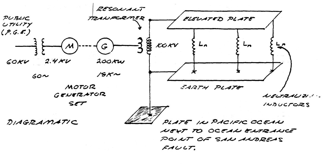
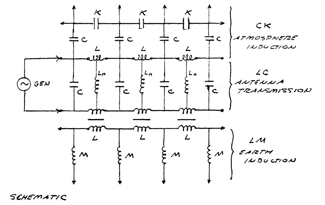
The alternators employed in these M.G. sets were fashioned after those developed by Tesla but became known as the Alexanderson alternators, after C.P. Steinmetz's protoge Ernst F.W. Alexanderson. These alternators delive�red currents to what is called the multiple loaded flat top antenna. A dia�gram and equivalent circuit of the Bolinas, California plant is shown in figure (1).
FIG (1)
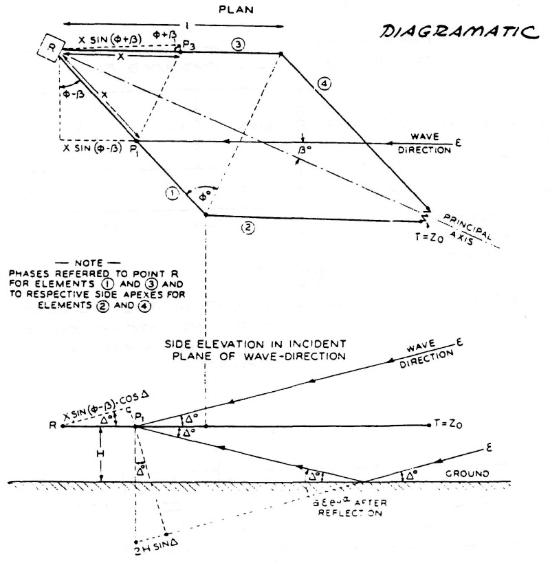
Upon completion of these wireless plants in 1919 the U.S. government established the Radio Corporation Of America (R.C.A.) to take control of the plants constructed upon U.S. territory. R.C.A., Marconi Wireless Co., and others went on to develop wireless (now radio) communication based upon transverse, or Hertzian, waveforms. The culmination of the transverse wave antenna was the R.C.A. type "D" director, later to become the well known rhombic antenna, figure (2).
FIG (2)
These developments firmly entrenched the use of Hertzian waves in the practice of wireless communication, thereby diverting interest from the waveforms discovered by Dr. Nikola Tesla. Tesla's progress in commercial development was further delayed by his absolute insistance upon establis�hing a perfect system, the "World System", of wireless power and commun�ication. The World System was much more costly and complex than the simple installations of Marconi. To quote Dr. Tesla's thoughts about the devel�opment of wireless at this point in history:
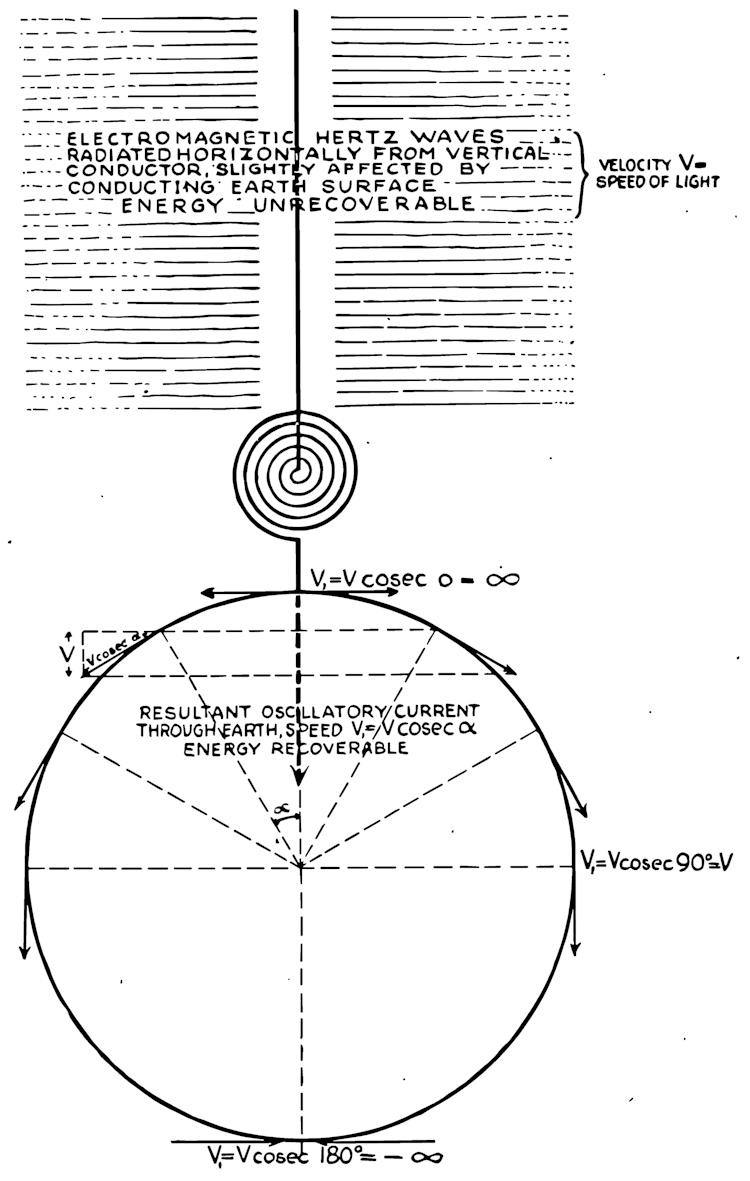
Dr. Tesla remained unswayed by these commercial developments and their impact upon scientific thought. Tesla understood that the transverse, or Hertzian. waveform was useless for the transmission of electric energy on an industrial scale. The scattering nature of these waves represents the primary limitation to efficient energy transfer, to quote:
This of course brings to mind the recent proposal to transmit from a satellite in outer space megawatts of photo-voltaic energy via a micro-wave beam down to the earth's surface.
b) The Tesla system
The system of transmission and reception of electric energy without the employment of connecting wires, or waveguides, as conceived by Dr. Tesla IS NOT the propagation of any type of electromagnetic wave, nor is it the excitation of the earth-ionosphere waveguide. Tesla's system employes resonant actions along lines, or rays, of ELECTRIC INDUCTION, these lines standing between the transmitter and the receiver, figure (3). The appar�atus for establishing these lines of induction is called the Tesla Magni�fying Transmitter (T.M.T.). The T.M.T. is a system of resonant transformers harmonically balanced to the electric condition of the earth. The mono-polar nature of the T.M.T. induction facilitates the ease of transmission and reception that this apparatus exhibits.
FIG (3)
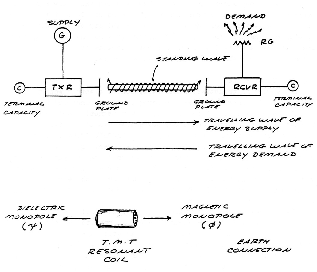
These lines of induction established by the T.M.T. are drawn into the high inductivity of the earth's interior; despite the conductivity of the surface, which would screen electro-magnetic waves. To illustrate this point consider Tesla's description of an experiment:
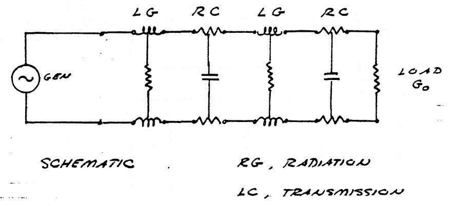
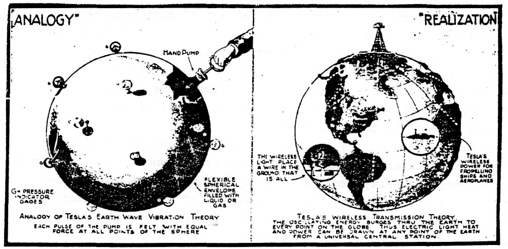
The dielectric induction thru the interior of the earth communicates the energy from the transmitter to the receiver as shown by figure (4). The unused portion of energy is reflected back to the transmitter more or less completely. Operating this energy reciprication between transmitter and receiver at the natural period and waveshape of the earth's own energy pulsation rate greatly overcomes the effect of distance, hence no significant loss of energy is apperent. Thus a standing wave of induction energy exists between the transmitter and receiver, or what can be called transponders, pulsating at one of the earth s natural harmonics. If the phase angle of the earth pulsation frequency lags the phase angle of the pulsating frequency energy is abstracted from the earth's supply of energy and delivered as "free energy" to the transponders.
It can therefore be seen that while the transmission of transverse waves involves the spraying of energy, with its consequent square law diminish�ment of energy density, and no hope of retrieving the unused energy, the Tesla system involves the direct connection of transmitter and receiver, via the pulsating lines of electric induction. Therefore, the transmitter and receiver are rendered as one apparatus.
FIG (4)
c) Operating principles of the T.M.T.
Because the energy is propagated thru the "ground" the question exists as to how to ground the apparatus, that is, how to establish an electric reference point, since the so called ground is now the hot terminal of the transponders, and therefore is incapable of also serving as an electric reference point. Here exists the singular feature of the Tesla O.C. tran�sformer in that the distributed mutual inductance and odd function resonance work to establish a virtual ground. This fundamental principle of virtual grounding is also to be found in the Tesla Tele-geodynamic Oscillator (T.G.O.) which serves as a mechanical analog to the T.M.T. The principle behind this is the geometrical reconfiguration of the fund�amental components of energy, the kinetic and potential, this reconfiguration resulting in the separation of cause and effect in not only time but also in space. The result hereof is the circumvention of the Newtonian laws of action and reaction. This allows for the production of heretofore unexp�lored phenomena.
Hence, the T.M.T. as well as the T.G.O. is capable of transmitting vibrations by virtue of the fact that it is SELF REFERENCING, thereby not requiring any ground, that is, no solid backing from which to push against. This relates to the saying "Give me a fulcrum and I will move the earth". Tesla found this fulcrum and moved the earth; both mechanically, producing a local earthquake in New York City; and electrically, producing a stand�ing lightning discharge at Colorado Springs (and possibly lightning else�where on the planet).
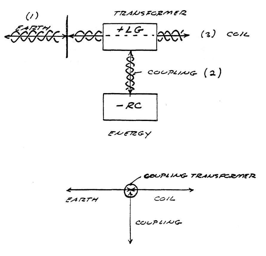
The Tesla transponder (T.M.T.) can be divided into FIVE distinct com�ponents:
- ) EARTH
- ) REFLECTING CAPACITANCE
- ) ENERGY TRANSFORMER
- ) COUPLING TRANSFORMER
- ) RESONANT COIL
The interconnection of these five components is shown by figure (5).
FIG (5)
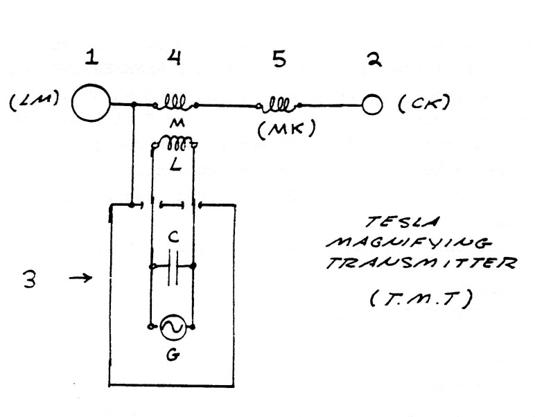
In this arrangement energy is continuously bounced back and forth between the earth and the reflecting capacitance at a rate tuned to a natural rate of the earth. This standing wave of energy pulsation is main�tained by the energy transformer which delivers electric energy to this standing wave via the coupling transformer. A certain percentage of this energy in the standing wave is refracted thru the earth-transformer refl�ection point and into the earth. This refracted energy establishes another standing wave in the earth. Hence, a pair of standing waves are produced which communicate energy thru the refraction. The oscillating resonant coil, tuned to an earth harmonic, establishes a virtual ground at one terminal of the coupling transformer thus rendering the earth terminal active from the standpoint relative to the electric conditions surrounding the apparatus. The coil terminal deginated as the reflecting capacitance appears active and the earth terminal appears to be neutral, whereas from the earth's standpoint the earth terminal is active. Thus, the reason for the popular notion that the reflecting capacitance Fig (5) is the output of the apparatus. In light of the virtual ground theory this is obviously not correct. See figure (6).
The electric conditions surrounding the T.M.T. no longer can be rep�resented by conventional, or electromagnetic, concepts because the system has converted the electro-magnetic energy of the dimensions
{$ W_11 = m c^2 = m frac{l^2}{t^2} $}
into a de-materialized, or mass free energy. The dimensions of this form of energy were given by Dr. Wilhelm Reich as
| {$ W_1 = frac{l^3}{t^2} $} | {$ m=l $} |
This de-materialized energy is the spatial analog of the reactive , or wattless- energy that is encountered in alternating current systems. Plasma discharges resulting from dielectric saturation (breakdown) of the dielectric medium that surrounds the T.M.T. no longer can be related to the laws of thermodynamics but are related to the laws of organic GROWTH, such as the spontaneous production of energy and Go" den ratio proportioning. It is of particular interest to note that these Phenomena serve as exper�imental verification of the theory of Cosmic Superimposition as put forth by Dr. Wilhelm Reich.
The pulsation of energy between the energy transformer, which is di�electric in nature, and the coupling transformer, which is magnetic in in nature represents an additional standing wave independent of that of the resonant coil and independent of that of the earth. This new standing wave is called an electric oscillation and represents a standing wave in the dimension of time. The energy of this standing wave is refracted thru the coupling transformer thereby exchanging energy with the other standing wave as shown schematically in figure (7). It can be seen that the T.M.T. involves three distinct standing waves in its operation, each coupled to the other thru two points of refraction. Each of these standing waves represents a distinct dimensional aspect:
- ) EARTH WAVE; SPACE DIMENSIONAL
- ) INTER TRANSFORMER; TIME DIMENSIONAL
- ) RESONANT COIL; EXTRA DIMENSIONAL
FIG (6)
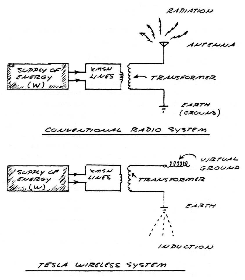
FIG (7)
The analogous relations in musical representation are:
- )HARMONY; SPACE DIMENSIONAL
- )RHYTM ; TIME DIMENSIONAL
- )MELODY ; EXTRA DIMENSIONAL
In order for this triple resonant, or sextic (6) energy transient to operate in consonant resonance, conjugate relation must be made to exist between all six energies. Unfortunately, very little theoretical knowledge exists for transients of more than double energy. This is primarily due to the limited understanding of the science of algebra with regard to the solutions of equations higher than second degree.
2) Induction in the dimension of time
a) History of discoveries
The elemental principles of electric induction were first discovered by Michael Faraday in the early part of the 19th century. Faraday con�sidered acting at a distance thru empty space as an improbable explanation of magnetic attraction and repulsion. By intuitive and experimental method he determined that space is pervaded with lines of induction. These lines of induction were considered by Faraday to be the polarization of the contiguous particles of the aether. The lines, or polarizations, displayed the curious property of not taking the shortest path between the poles of an inductor, but followed curved paths thru space. This curvature of induction was unacceptable to Faraday's contemporaries and he was sharp�ly criticised for this discovery.
In the course of his experimental researches Faraday found that when a magnetic field surrounding an electric conductor is altered so as to change the amount of induction surrounding this conductor, an electro�motive force (E.M.F.) is produced along the conductor length in propor�tion to the quickness of the alteration. Algebraically it is
| $ E = \frac {\varphi} {t} $ | Lines per second (Volts) |
That is, the E.M.F. of magnitude E is directly proportional to the total number of lines of induction $\varphi$ enclosing the conductor, and is inversely proportional to the length of time t required to produce or consume these lines of induction. In practical work the E.M.F. is known as voltage. This discovery marks the beginning of our knowledge of transformer theory, and is called the LAW OF ELECTRO-MAGNETIC INDUCTION. Faraday also the existence of another form of lines of induction distinct from the mag�netic form. These lines appear around what are called "electo-static charges", and were given the name DIELECTRIC lines of induction. This field of induction is complimentary to the magnetic field of induction.
The experimental researches of Michael Faraday greatly impressed two of perhaps the most influential electrical scientists of the 19th century, J.C. Maxwell and J.J. Thompson. Maxwell sought to translate the experimental researches of Faraday into mathematical form in order to provide a more quanitive understanding of electric induction. Maxwell discovered a fundamental law complimentary to the law of electro�magnetic induction, this being the LAW OF DIELECTRIC INDUCTION, or what is often called displacement current. Algebraically it is,
| $ I = \frac {\psi} {t} $ | Lines per second (Amperes) |
That is, the current of magnitude I is directly proportional to the number of lines of dielectric induction $\psi$ terminating on the conductor surface, and inversely proportional to the length of time t required to produce or consume these lines of induction. In practical work this is known as the amperes.
The complimentary nature of magnetic and dielectric inductions led maxwell to discover the existance of a constant numerical proportion between the units of measure in magnetism and the units of measure in. dielectricity, this constant being numerically equal to the velocity of light squared. This famous discovery led Maxwell to the THEORY OF ELECTRO-MAGNETISM, this theory stating that electric waves are ident�ical to waves of light, and thereby gave the notion that magnetism and dielectricity are inseparable.
The Maxwell theory of electro-magnetism dominated research into electric waves, particularly after the experiments of H. Hertz. Nikola Tesla comment on this matter:
Unfortunately this time has not yet arrived.
Prof. J.J. Thompson took a much less mathematical approach and more physical approach to Faraday's discoveries. Prof. Thompson considered Faraday's contiguous aether particles and lines of induction as CONCRETE PHYSICAL REALITIES, despite the shift in contemporary thought (cir 1900) back to what resembles action at a distance thru an aetherless, and now a spiritless, dead, space.
Thompson considered the propagation of magnetic inductions as dis�tinctly INDEPENDENT of each other, rather than these two inductions propagating cojointly as given by the theory of electro-magnetism. He conceived the propagation of magnetic induction, because of the lines being transverse to the direction of propagation, as being retarded by the broadside drag they encounter in their motion thru the aether; Whereas the propagation of dielectric induction, because of these lines being directed along the path of propagation, are not retarded, but glide smoothly thru the aether with little or no opposition to motion.
Analogously, the propagation of a parachute thru the atmosphere is akin to magnetic propagation and hence the effect of drag, whereas the prop�agation of a missile thru the atmosphere is akin to dielectric propagation. Hence, dielectric induction propagates faster and thus arrives sooner than the magnetic induction, and thus sooner than the electro-magnetic energy. This concept is of prime importance for the understanding of the works of Dr. Nikola Tesla.
In his search for the contiguous particles of the aether Prof. Thompson discovered what is known as the electron. Much misunderstanding has developed with regard to the relation between this particle and dielec�tric induction. This has worked much harm into the proper understanding of Tesla's discoveries, and the understanding of electricity in general. To quote C.P. Steinmetz on this matter:
In 1854 Sir William Thompson, known also as Lord Kelvin, published the theory of electric oscillations. This theory demonstrated the inter�action of the law of electro-magnetic induction with the law of dielectric induction, forming the lav; of electric induction in the dimension of time. Algebraically it is,
| $ P = \frac {\phi} {t^2} = EI $ | Units per second squared (Watts) |
In practical work this is called the electric power, or wattage.
This theory, and its further development by Helmholtz, Heaviside, and Steinmetz,represents a fundamental principle behind nearly all of Tesla's apparatus.
Lord Kelvin felt that it was possible to establish compressional waves, such as sound waves, thru the luminiferous aether, these waves being a version of Maxwell's displacement current. This current, often called capacitor current, flows thru electric insulators, and even thru so called empty space. No conductors or electron flux is involved with this current. Kelvin indicated his feelings that these waves must prop�agate faster than the velocity of light. To quote Kelvin's description of the actions of the induction in the space between the plates of a capacitor fed by an alternator:
The velocity of dielectric propagation was experimentally verified by Prof. Wheatstone to be $\pi$/2 times faster than the velocity of light. Tesla also states this velocity in his writings on wave propagation.
In view of these scientific discoveries, and the fact that Oliver Heaviside developed a theory of faster than light electrons which was confirmed by Dr. Tesla, it is a wonder how the present notions of electro-magnetism and its limiting velocity as purported by Einstein an his follo�wers have dominated electric theory. It is of particular interest to note that C.P. Steinmetz did not consider Hertzian waves as transmission of energy but as energy loss by the hysteresis of the aether.
3) Theoretical concepts of Tesla's discoveries
TESLA, PHYSICS AND ELECTRICITY
Research into the works of Nikola Tesla reveals electric phenomena that behave contrary to the theory of electricity in present use. Explanation of Tesla's inventions has been given from the standpoint of physics, yielding many misconceptions. The science of physics is based on the phenomena surrounding particles and mass, which finds little application in the study of electric phenomena.
The explanation of Tesla's discoveries are to be found in the science of electricity rather than the science of physics. The sci�ence of electricity has been dormant since the days (1900) of Stein�metz, Tesla and Heaviside. This is primarily due to vested interests which we may call the "Edison Effect." This material serves as a preface to a theoretical investigation of N. Tesla's discoveries by the examination of the rotating magnetic field and high frequency transformer. It is assumed that the reader is acquainted with the commonly available material on Tesla, and possesses a basic knowledge of mechanics and electricity.
THE ROTATING MAGNETIC FIELD
In the general electromechanical transformer energy is exchanged between mechanical and electric form. Such an apparatus typically employs a system of moving inductance coils and field magnets. It is desirable that the mechanical energy produced or consumed by of ro�tational form in order to operate with pumps, engines, turbines, etc. The method of producing rotary force, without the use of mechanical rectifiers known as commutators, was discovered by Nikola Tesla in the late 1800s and is known as the rotating magnetic field.
ELEMENTAL PRINCIPLES
An examination of the rudimentary interaction between inductance coils and field magnets will provide some insight into the principles behind the rotary magnetic field.
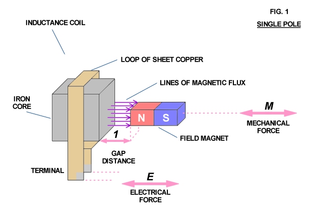
Consider a simple electromechanical device consisting of a piece of iron with a copper loop winding around it along with a small bar magnet (Fig. 1). Any variation in the distance (l) between the pole faces of the inductance coil and magnet produces an electromotive force (voltage) at the terminals of the copper loon resulting from the field magnet's lines of force passing through the iron core of the inductance coil. The magnitude of this E.M.F. is directly propor�tional to the speed at which the distance (l) is varied and the quan�tity of magnetism issuing from the field magnet pole face.
Conversely, if an electromotive force is applied to the induc�tance coil terminals, the distance (l) varies at a speed directly proportional to the strength of the E.M.F. and the quantity of magnet�ism issuing from the field magnet pole face. Thus electrical force and mechanical force are combined in this device.
If a flow of electrical energy (watts) is taken from the coil terminals and delivered to a load mechanical resistancy (friction) appears at the field magnet as a result of magnetic attraction and repulsion between the magnet and iron core. Mechanical force applied to the field magnet in order to move it results in power flow out of the coil. This flow of power generates an oppositional or counter electromotive force which repels the field magnet against the mechan�ical force. This results in work having to be expended in order to move the magnet. However this work is not lost but is delivered to the electric load.
Conversely, if the field magnet is to deliver mechanical energy to a load, with an externally E.M.F. applied to the coil terminals, the field magnet tends to be held stationary by the resistancy of the connected mechanical load. Since the field magnet is not in motion it cannot develop a counter E.M.F. in the coil to meet the externally applied E.M.F. Thus electrical energy flows into the coil and is de�livered to the field magnet as work via magnetic actions, causing it to move and perform work on the load.
Hence, mechanical energy and electrical energy are rendered on and the same by this electromechanical apparatus. Connecting this apparatus to a source of reciprocating mechanical energy produces an alternating electromotive force at the coil terminals, thus a linear or longitudinal A.C. generator. Connecting this apparatus to a source of alternating electric energy produces a reciprocating mechanical force at the field magnet, thus a linear A.C. motor. In either mode of operation the field magnet reciprocates in a manner not unlike the piston of the internal combustion engine. Rotary motion is not possible without the use of a crankshaft and flywheel.
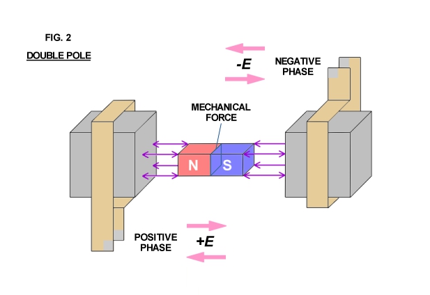
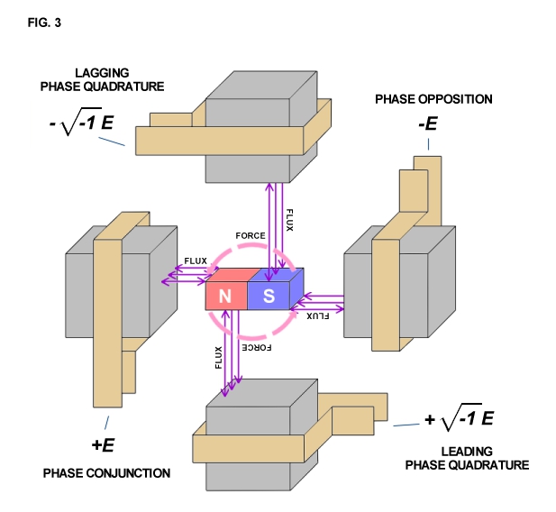
Arranging two inductance coils in a line as shown in Fig. 2 and connecting these coils to a pair of alternating E.M.F.s that are out of step by 1/2 of an alternating cycle with respect to each other results in the mechanical force being directed inwardly into the molecular spaces (inner space) within the field magnet. The field magnet is alternately stretched and compressed by magnetic action and no external force is evident except as vibration and heat. However, arranging two of the pairs shown in Fig. 2 at right angles to each other, connecting each to a pair of alternating E.M.F.s that are out of phase or step by one quarter cycle (quadrature) with respect to each other produces a rotating travelling wave of magnetism, that is, a whirling virtual magnetic pole.
This virtual pole travels from one pole face to the next during the time interval of one quarter cycle, thus making one complete revolution around all the pole faces for each cycle of alternation of the E.M.F.s. The field magnet aligns with the virtual pole, locking in with the rotary magnetic wave, thereby producing rotational force.
An analogy may assist in understanding this phenomena. Consider that the sun appears to revolve around the earth. Imagine the sun as a large magnetic pole and your mind's view of it as the field magnet. As the sun sets off in the distant horizon, it seemingly disappears. However, the sun is not gone but it is high noon 90 degrees, or one quarter, the way around the planet. Now imagine moving with the sun around the planet, always keeping up with it so as to maintain the constant appearance of high noon. Thusly, one would be carried round and round the planet, just as the field magnet is carried round and round by the virtual pole. In this condition the sun would appear stationary in the sky, with the earth flying backwards underfoot. Inspired to thinking of this relation by the poet Goethe, Tesla per�cieved the entire theory and application of alternating electric ener�gy, principally the rotating magnetic wave.
"The glow retreats, done is the day of toil; it yonder hastes, new fields of life exploring; Ah, that no wing can lift me from the soil, upon its track to follow, follow soaring..."
ROTATIONAL WAVES
The fundamental principle behind the production of the rotary magnetic field serves as the principle behind all periodic electric waves. It is therefore of interest to investigate the discovery a little further.
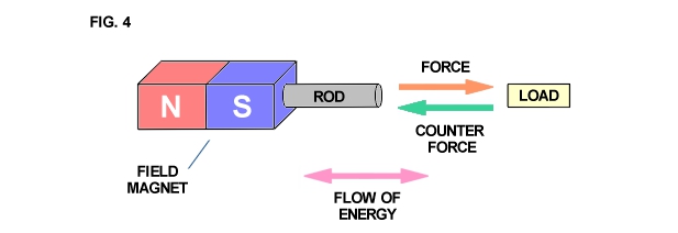
The apparatus shown in Fig. 1 develops mechanical force along the axis of the field magnet as shown in Fig. 4. Likewise, mechanical counterforce is applied along the axis of the field magnet. Hence, if work is to be drawn or supplied respectively to the field magnet from an external apparatus, a connecting rod is required between the two machines. The flow of energy is along the axis of the rod and thus is in line (space conjunction) with the forces involved. A simple analogy is a hammer and nail. The hammer supplies mechanical force to the nail, the nail transmitting the force into the wood. The counter-force tends to make the hammer bounce off the nail. However, the wood is soft and cannot reflect a strong counterforce back up the nail and into the hammer. Thus the nail slides into the wood absorbing mech�anical energy from the hammer which is dissipated into the wood.
The apparatus of Fig. 2 develops mechanical force axially also, but it is entirely concentrated within the molecular space. Any counterforce must push back along the same axis. Thus the work is also along axis like Fig. 4 and is delivered to the molecular struc�ture. The analogy is two hammers striking a steel block from op�posite sides, pounding the block and producing heat and vibration within it.
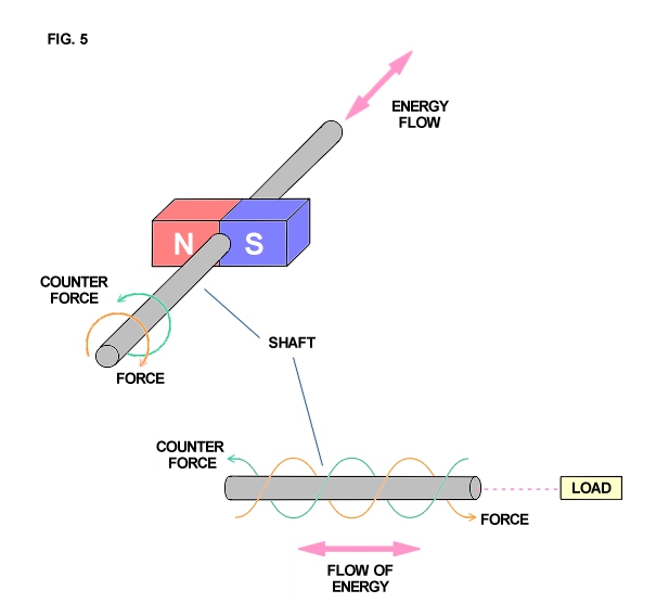
The apparatus of Fig. 3 produces a quite different wave form (Fig. 5). The mechanical force delivered to the shaft is applied at a right angle to the axis in clockwise direction. The counterforce is applied in the apposite rotational sense or counter-clockwise dir�ection at a right angle to the axis. The flow of mechanical energy is still along the shaft as in Fig. 4, however, it no longer pulsates in magnitude with the cycle but it continues, quite like the flow of electric energy in a direct current circuit,
An analogy is a screw and screwdriver. The screwdriver is forced rotationally clockwise by the hand or other motive force, The counter force appears in opposition, that is counterclockwise, thereby ar�resting the rotation of the screwdriver. However, the wood is soft and cannot reflect the counterforce back into the screwdriver. Thus the screw travels longitudinally into the wood, perpendicular to the rotation of the screwdriver. The form of this wave has been of great interest to a wide variety of fields of endeavor. It has been called the Caduceus coil, spinning wave, double helix, solar cross, and of course the rotating magnetic field. Applications are as wide ranging, from sewage treat�ment plants and guided missies all the way to the Van Tassel Integra�tron and astrology.
The Oscillating Current Transformer
Originally published in JBR, May-June 1986.
The Oscillating Current Transformer
The oscillating current transformer functions quite differently than a conventional transformer in that the law of dielectric in�duction is utilized as well as the familiar law of magnetic induct�ion. The propagation of waves along the coil axis does not resemble the propagation of waves along a conventional transmission line, but is complicated by inter-turn capacitance & mutual magnetic inductance. In this respect the O.C. transformer does not behave like a resonant transmission line, nor a R.C.L. circuit, but more like a special type of wave guide. Perhaps the most important feature of the O.C. transformer is that in the course of propa�gation along the coil axis the electric energy is dematerialized, that is, rendered mass free energy resembling Dr. Wilhelm Reich's Orgone Energy in its behavior. It is this feature that renders the O.C. transformer useful for wireless power transmission and reception, and gives the O.C. transformer singular importance in the study of Dr. Tesla's research.
FUNDAMENTALS OF COIL INDUCTION
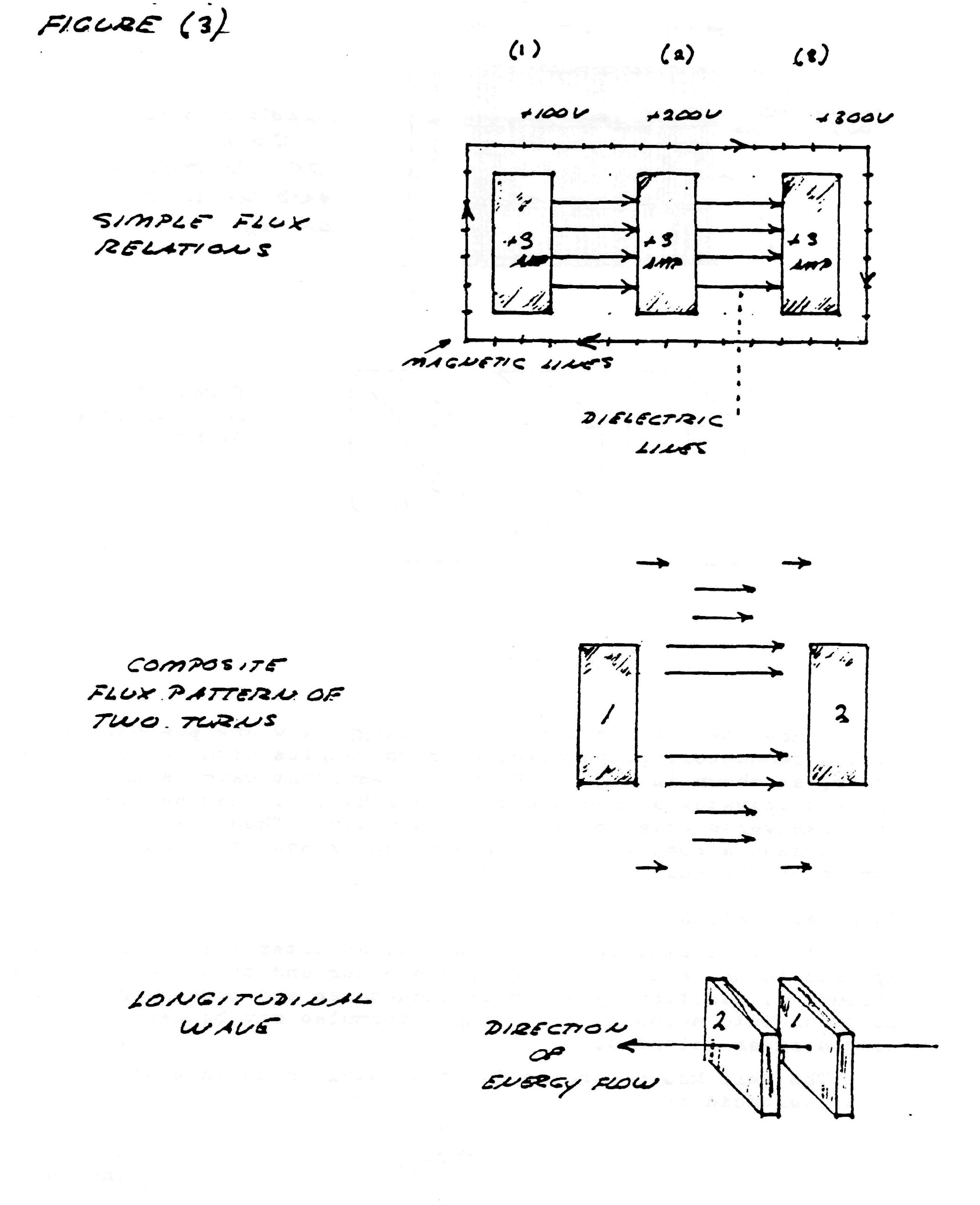
Consider the elemental slice of a coil shown in fig. 1. Between the turns 1,2 & 3 of the coiled conductor exists a complex electric wave consisting of two basic components. In one component (fig. 2), the lines of magnetic and dielectric flux cross at right angles, producing a photon flux perpendicular to these crossings, hereby propagating energy along the gap, parallel to the conductors and around the coil. Th�s is the transverse electro-magnetic wave. In the other component, shown in fig. 3, the lines of magnetic flux do not cross but unite along the same axis, perpendicular to the coil conductors, hereby energy is conveyed along the coil axis. This is the Longitudinal Magneto-Dielectric Wave.
Figure (1)
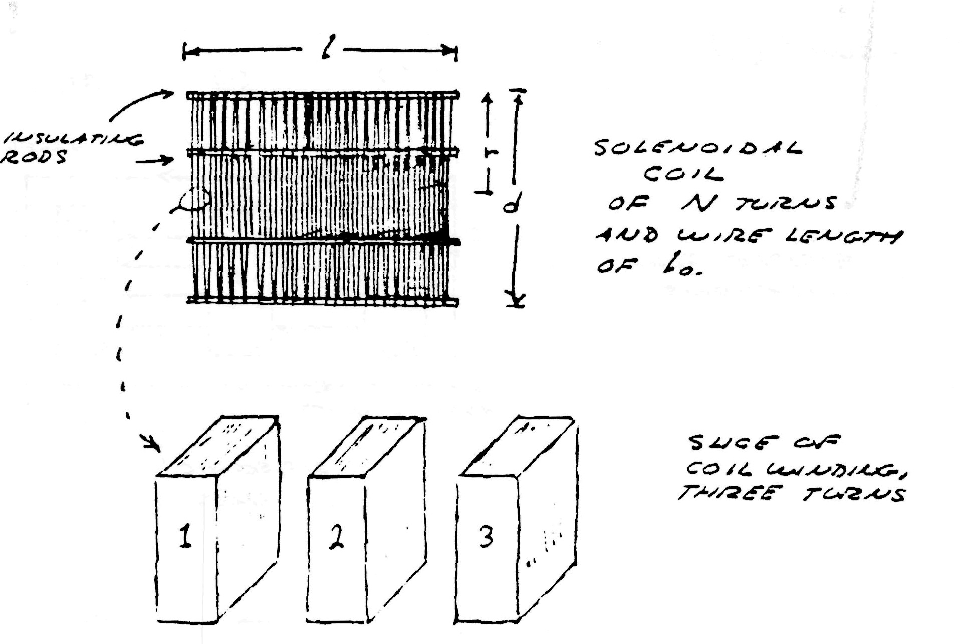
Figure (2)
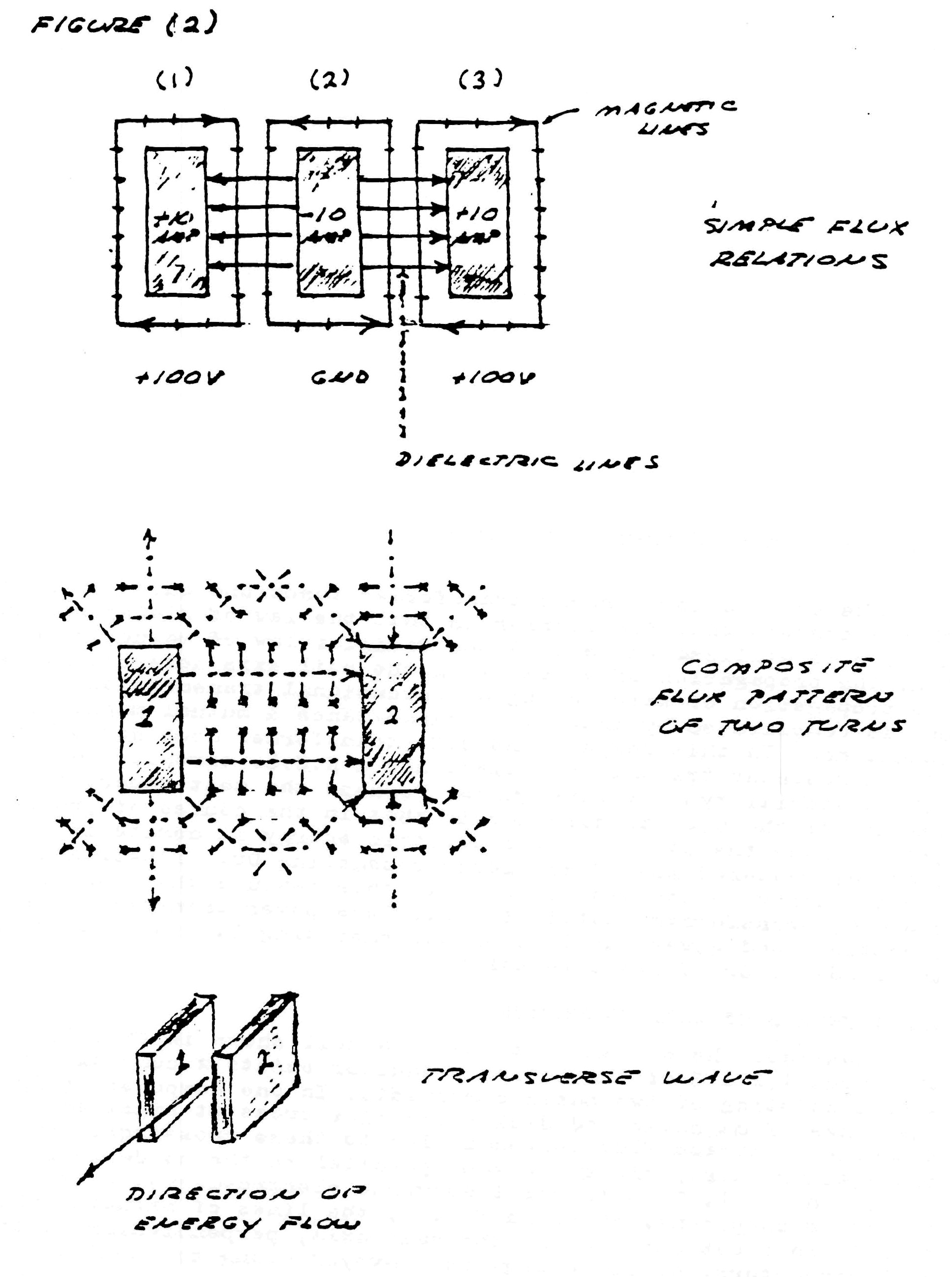
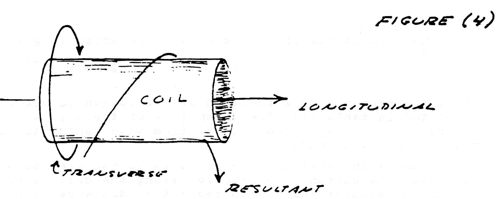
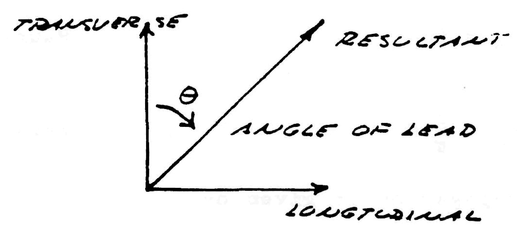
Hence, two distinct forms of energy flow are present in the coiled conductor, propagating at right angles with respect to each other, as shown in fig. 4. Hereby a resultant wave is produced which propagates around the coil in a helical fashion, leading the transverse wave between the conductors. Thus the oscillating coil posses a complex wavelength which is shorter than the wave�length of the coiled conductor.
COIL CALCULATION
If the assumptions are made that an alternating current is applied to one end of the coil, the other end of the coil is open circuited, Additionally external inductance and capacitance must be taken into account, then simple formulae may be derived for a single layer solenoid.
The well known formula for the total inductance of a single layer solenoid is
| $ L = \frac{r^2 N^2}{ (9r + 10l) }$ | $ x 10^{-6}$ Henry (inches) (1) |
Where:
- r is coil radius in inches
- l is coil length in inches
- N is number of turns
| $ L = \frac{31.6 r_1^2 N^2}{ (6 r_1 + 9l + 10(r_2-r_1)) }$ | microHenry |
| $ L = \frac{r^2 N^2}{ (8 r + 11w) }$ | microHenry |
Figure (3)
The capacitance of a single layer solenoid is given by the formula
| $C = pr$ | $ 2.54 x 10^{-12}$ Farads (inches) (2) |
where the factor p is a function of the length to diameter ratio, tabulated in table (1). The dimensions of the coil are shown in figure (1). The capacitance is minimum when length to diameter ratio is equal to one.
Because the coil is assumed to be in oscillation with a stand�ing wave, the current distribution along the coil is not uniform, but varies sinusoidially with respect to distance along the coil. This alters the results obtained by equation (1), thus for resonance
| $L_0 = \frac12 L$ | Henrys (3) |
likewise, for capacitance
| $C_0 = \frac{8}{\pi} C$ | Farads (4) |
Hereby the velocity of propagation is given by
| $\begin{eqnarray} V_0 & = & \frac{1}{\sqrt {L_0 C_0}} \\ & = & \eta V_c \end{eqnarray}$ | Units/sec (5) |
Where
| $ V_c = \frac{1}{\sqrt {\mu \epsilon}} $ | Inch/sec (6) |
That is, the velocity of light, and
| $\begin{eqnarray} V_0 & = & \eta V_c \\ & = & \left[ \begin{array}{cc} \frac{1.77}{p} + \frac{3.94}{p}n \end{array} \right]^\frac12 \end{eqnarray}$ | $2 \pi 10^9$ Inch/sec (7) |
Where n = the ratio of coil length to coil diameter. The values of propagation factor $\eta$ are tabulated in table (2).
| $ F_{res} = (0.39 * ln(h/d) + 1.19) * 75e6 / l $ | (Hertz) |
Thus, the frequency of oscillation or resonance of the coil is given by the relation
| $ F_0 = \frac{V_0}{ (l_0 . 4) } $ | Cycles/sec (8) |
Where $l_0$ = total length of the coiled conductor in inches.
Figure (4)
The characteristic impedance of the resonant coil is given by
| $ Z_c = \sqrt {\frac{L_0}{C_0}}$ | Ohms (9) |
Hence,
| $ Z_c = N Z_s $ | Ohms (10) |
Where
| $ Z_s = \left[ \begin{array}{cc} (182.9 + 406.4n)p \end{array} \right]^\frac12 $ | $ \frac{\pi}{2} 10^3$ Ohms (inches) (11) |
and N = number of turns. The values of sheet impedance, $Z_s$, are tabulated in table (3).
The time constant of the coil, that is, the rate of energy dissipation due to coil resistance is given by the approximate formula
| $ u = \frac{R_0}{2 L_0} = ( \frac{2.72}{r}+ \frac{2.13}{l}) \pi \sqrt{F_0} $ | Nepers/sec (inches) (12) |
Where
- r = coil radius
- l = coil length
In general, the dissipation of the coil's oscillating energy by conductor resistance:
- Decreases with increase of coil diameter, d;
- Decreases with increase of coil length, l, rapidly when the ratio, n, of length to diameter is small with little decrease beyond n equal to unity;
- Is minimum when the ratio of wire diameter to coil pitch is 60%.
By examination of the attached tables, (1), (2) & (3), it is seen that the long coils of popular designs do not result in optimum performance. In general, coils should be short and wide, and not longer than n=1. The frequency is usually given as $F_0 = V_c / \lambda_0$ which by equation (7) is incorrect. Winding on solid or continuous formers rather than spaced slender rods, as shown in figure (1), greatly retards wave propagation as indicated in equation (6), thereby seriously distorting the wave. The dielectric constant of the coil,$\epsilon$ , should be as close to unity as is physically possible to insure high efficiency of transformation.
The equations for the voltampere relations of the oscillating coil are
| $ \dot E_1 = j ( Z_c Y_0 + \delta) \dot E_0 $ | Complex Input Voltage (13) |
| $ \dot I_1 = j ( Y_c Z_0 + \delta) \dot I_0 $ | Complex Input Current (14) |
| $ Z_1 = \frac{Z_c Y_0 + \delta}{Y_c Z_0 +\delta} Z_0 $ | Input Impedance, Ohms (15) |
Where
- $ \dot E_0 = $ Voltage on elevated terminal
- $ \dot I_0 = $ Current into elevated terminal
- $ Y_c = Z_c^{-1}$
- $ Z_0 = $ Terminal impedance
- $ Y_0 = $ Terminal admittance
- $ \delta = \frac{u}{2 F_0} = $ Decrement
- $ j =$ root of $\sqrt{-1}$
For negligible losses and absolute values
| $ E_1 = ( Z_c 2 \pi F_0 C_0) E_0 $ | Volts (16) |
| $ I_1 = ( Y_c / 2 \pi F_0 C_0) I_0 $ | Amperes (17) |
Where
- $C_0 =$ Terminal capacitance
By the law of conservation of energy
| $ E_1 I_1 = E_0 I_0 $ | Volt-Amperes (18) |
If the terminal capacitance is small then the approximate input/ output relations of the Tesla coil are given by
| $ E_0 = Z_c I_1 $ | Output Volts (19) |
| $ I_1 = E_0 Y_c $ | Input Amperes (20) |
| $ I_0 = Y_c E_1 $ | Output Amperes (21) |
| $ E_1 = I_0 Z_c $ | Input Volts (22) |
TABLE (1) Coil Capacitance Factor
| Length/Width = n | Factor P | Length/Width = n | Factor P |
| 0.10 | 0.96 | 0.80 | 0.46 |
| 0.15 | 0.79 | 0.90 | 0.46 |
| 0.20 | 0.70 | 1.00 | 0.46 |
| 0.25 | 0.64 | 1.5 | 0.47 |
| 0.30 | 0.60 | 2.0 | 0.50 |
| 0.35 | 0.57 | 2.5 | 0.56 |
| 0.40 | 0.54 | 3.0 | 0.61 |
| 0.45 | 0.52 | 3.5 | 0.67 |
| 0.50 | 0.50 | 4.0 | 0.72 |
| 0.60 | 0.48 | 4.5 | 0.77 |
| 0.70 | 0.47 | 5.0 | 0.81 |
TABLE (2)
| Length/Width = n | $V_0$ Inches/Sec | Percent Luminal Velocity = $\eta$ |
| 0.10 | 9.42 x 10^9 | 79.8% |
| 0.15 | 10.9 | 92.2 |
| 0.20 | 12.0 | 102 |
| 0.25 | 13.0 | 110 |
| 0.30 | 13.9 | 118 |
| 0.35 | 14.8 | 125 |
| 0.40 | 15.6 | 132 |
| 0.45 | 16.4 | 139 |
| 0.50 | 17.2 | 146 |
| 0.60 | 18.4 | 156 |
| 0.70 | 19.5 | 165 |
| 0.80 | 20.5 | 176 |
| 0.90 | 21.4 | 181 |
| 1.00 | 22.1 | 187 |
| 1.5 | 25.4 | 215 |
| 2.0 | 27.6 | 234 |
| 2.5 | 28.7 | 243 |
| 3.0 | 29.7 | 251 |
| 3.5 | 30.3 | 257 |
| 4.0 | 30.9 | 262 |
| 4.5 | 31.6 | 268 |
| 5.0 | 32.4 | 274 |
| 6.0 | 33.0 | 279 |
| 7.0 | 33.9 | 287 |
TABLE (3)
| L/W =n | $Z_s$ |
| 0.10 | 0.107 x 10 |
| 0.15 | 0.070 |
| 0.20 | 0.116 |
| 0.25 | 0.116 |
| 0.30 | 0.116 |
| 0.35 | 0.115 |
| 0.40 | 0.115 |
| 0.45 | 0.114 |
| 0.50 | 0.113 |
| 0.60 | 0.110 |
| 0.70 | 0.106 |
| 0.80 | 0.103 |
| 0.90 | 0.099 |
| 1.00 | 0.095 |
| 1.5 | 0.081 |
| 2.0 | 0.070 |
| 2.5 | 0.061 |
| 3.0 | 0.054 |
| 3.5 | 0.048 |
| 4.0 | 0.044 |
| 4.5 | 0.040 |
| 5.0 | 0.037 |
| 6.0 | 0.032 |
| 7.0 | 0.028 |
Books by Eric Dollard
CONDENSED INTRO TO TESLA TRANSFORMERS. This book is an abstract of theory and construction techniques of Tesla transformers. It is the result of experimental investigations and theoretical considerations. Includes relevant Tesla patent and an article on capacity by Fritz Lowenstein, Tesla's assistant. (BSRA #TE-1)
INTRODUCTION TO DIELECTRIC & MAGNETIC DISCHARGES IN ELECTRICAL WINDINGS, Theory of abrupt electrical oscillations such as those used by Tesla for experimental researches. Contains ELECTRICAL OSCILLA� TIONS IN ANTENNAE AND INDUCTION COILS by John Miller, 1919. This is one of the few articles containing equations useful to the design of Tesla coils. (BSRA #TE-2)
IV) Induction in the dimension of space
a) Product of conjugate pair of inductions
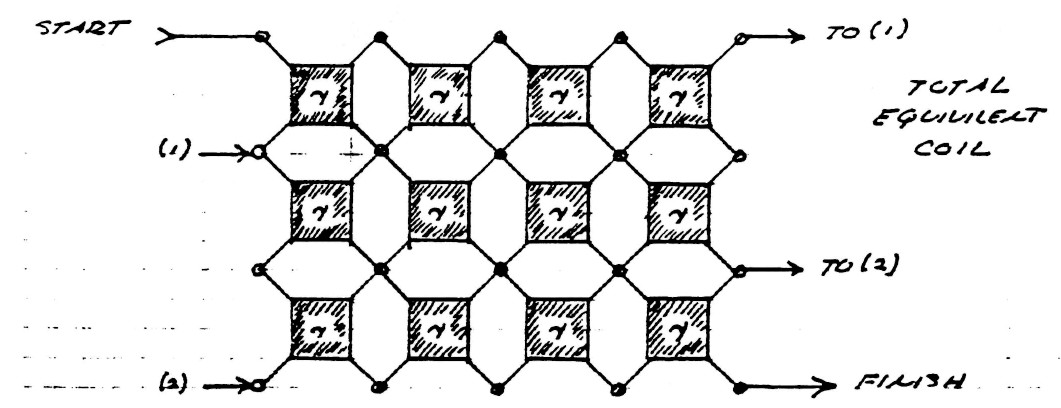
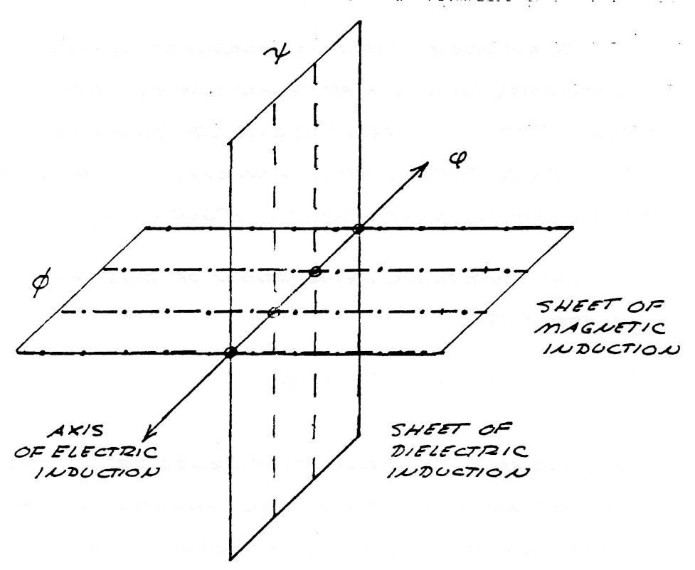
The wave theories in present usage for the study of electric propagation along coils and kindred apparatus all suffer from the fundamental drawback that they are representations of energy propagation along a single line or axis. The equivalent circuit of coil propagation is, however best presented as in figure (1), that is, two perpendicular paths for induction. Thus the propagation can occur in any direction on the surface of the mesh given by figure (1).
The nature of electric energy varies with the direction of propagation and departs significantly from the common electro-magnetic form when the path is no longer along the usual axis. This departure in form is of singular importance in the study of Tesla's discoveries.
FIG (1)
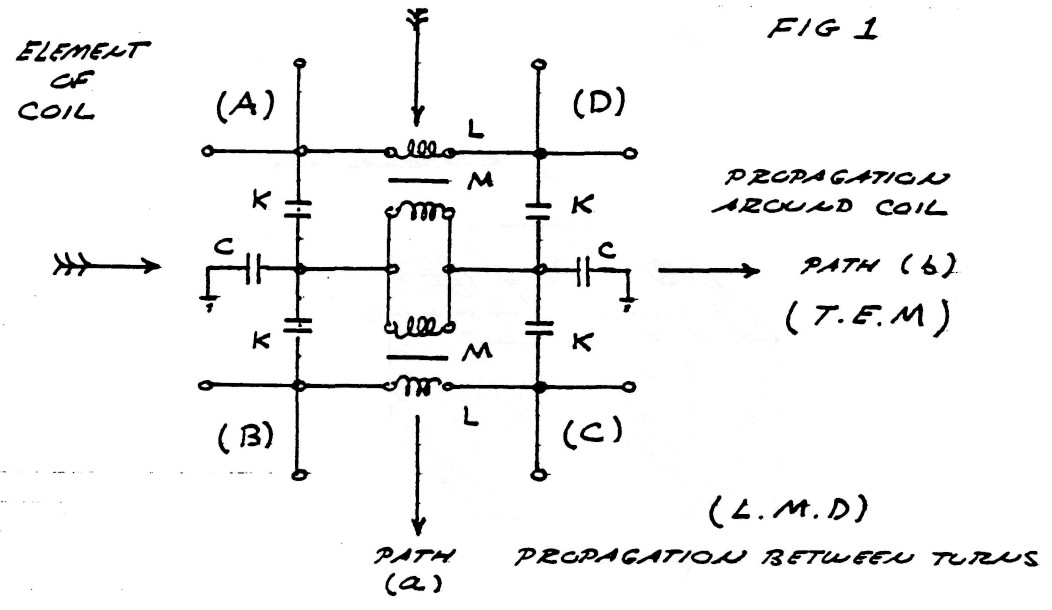
Since electric energy is the product in space of the flux of magnetic induction, and the flux of dielectric induction, the nature of these fluxes, and the nature of their products, determines the characteristics of electric energy that appear in the Tesla Oscillating Current Transformer. It is thus important to investigate the nature of these components of electric energy.
When electric energy exists in any system of electric "conductors" certain phenomena appear in the space surrounding the conductors, that is magetic and dielectric actions manifest themselves in the surrounding aether.
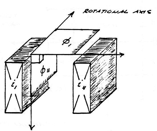
Surrounding the conductors s what is called the magnetic field of induction. The intensity of this magnetic field is given my the total number of magnetic lines, ϕ0, filling the surrounding space. The portion of the total magnetic induction which is parallel to the surface of the conductor is called the transverse magnetic induction, ϕ11, and that portion of the total magnetic induction which is perpendicular to the surface of the conductors is called the longitudinal magnetic induction ϕ1.
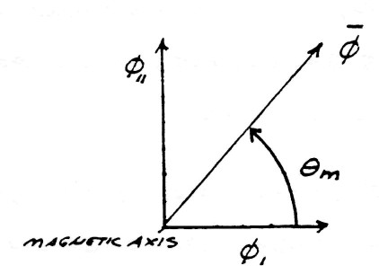
In general the transverse magnetic induction exists at right angles to the flow of energy and the longitudinal magnetic induction exists in line with the flow of energy. The geometric relations are given in figure (2).
FIG (2)
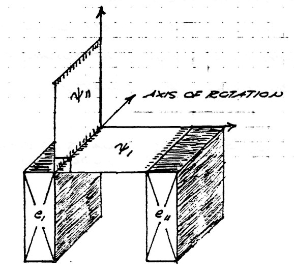
Issuing from the surface of the conductors is what is called the dielectric field. The intensity of the dielectric field is given by the total number of dielectric lines of induction, ψ0. The portion of the total dielectric induction that terminates upon surfaces in the direction of the flow of energy is called the longitudinal dielectric induction, ψ1, and the portion that terminates upon surfaces perpendicular to the flow of energy is called the transverse dielectric induction. The geometric relations are given in figure (3).
FIG (3)
The total magnetic field of induction, $\varphi_0$, and the total dielectric field of induction, $\psi_0$, together constitute the total electric field of induction, $\phi_0$, that is
| $ \phi_0 = \varphi_0 \psi_0 $ | Units of electric induction |
b) Transverse and Longitudinal components
Transverse electro-magnetic waves, sometimes called Hertzian waves, are the result of the perpendicular crossing in space of lines of dielectric induction, $\psi$, and lines of magnetic induction, $\varphi$, figure(4).
FIG (4)
The symbolic expression of this geometric relation is
| $ \phi = \psi \times \varphi $ | (1) |
This relation is called the cross product of the magnetic and dielectric inductions that constitute the electric induction. This relation is the basis for what is known as the Poynting vector, first discovered by Oliver Heaviside.
The trigonometric edpression of this relation is
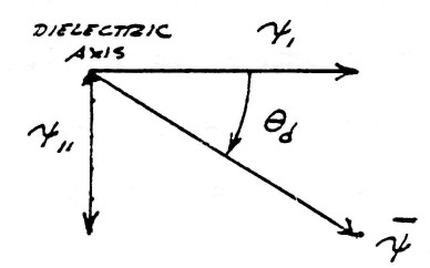
| $ \phi = \phi_0 \: sin \: \theta $ | (2) |
where $\theta$ is the angle of crossing betweeen the lines of $\psi$ and the lines of $\varphi$
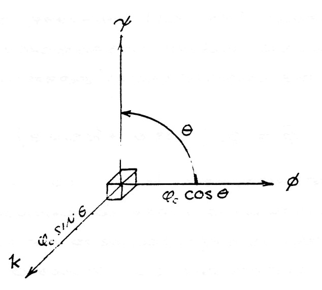
It was shown by Prof. Alexander Macfarlane in "The Imaginary of Algebra" presented before the American Association for the Advancement of Science, Vol XLI (1891-1894), that it is a general principle of spherical trigonometry that the complete versor expression of $\phi$ is
| $ \bar \phi = \phi_0 ( cos \: \theta + k \: sin \: \theta ) $ | (3) |
where the symbol k is no more than a distinguishing index indicating that the sine term is perpendicular to the plane in which the crossings of $\psi$ and $\varphi$ occur, figure (5).
By substituting the relations
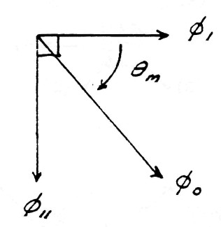
| $ \begin{eqnarray} \phi_1 & = & { \phi_0 \: cos \: \theta } \\ \phi_{11} & = & { \phi_0 \: sin \: \theta } \\ \end{eqnarray} $ | $\Bigg \rbrace$ (4) |
FIG (5)
The symbolic expression of the complex induction is given by
| $ \bar \phi = \phi_1 + k \phi_{11} $ | (5) |
Hence, the flux of electro-magnetic induction is directed perpendicular to the inductions which give rise to it, propagating in the direction k.
The dimensions of electro-magnetiic energy are given by
| $\begin{eqnarray} W & = & m c^2 \\ & = & \begin{array}{cc} m \frac{l^2}{t^2}\end{array} \end{eqnarray}$ | Watt . sec (6) |
And the dimensions of magnetic flux are
| $ \varphi $ | $ = \frac{i}{W} $ | lines (7) |
| $ = \frac{l^2}{t} \frac{m}{\psi} $ | (8) |
Substituting equation (7) into (6) and substituting the law of dielectric induction
| $ i = \frac{\psi}{t} $ | lines/sec |
gives the dimensions of the transverse electro-magnetic induction as
| $ \phi_{11} $ | $ = m c^2 T $ | Watt . sec� |
| $ = m \frac{l^2}{t} $ | (9) |
where T is the time interval during which energy is exchanged between magnetic and dielectric forms of energy storage. The dimensions of equation (9) usually are given as the numerical quantity
| $ \phi_{11} = 6.6234 $ | $ x 10^{-34} $ | Watt . sec� |
or integer multiples thereof. This is usually portraid as a flux of these units of energy.time flowing along direction k, called a flux of photons.
The fundamental relation given by the equation (8) indicates that the electro-magnetic induction $\phi_{11}$ is only a partial component of the complete electric induction, $\bar \phi$, due to the existance of the complimentary component
| $ \phi_1 = cos \: \theta $ |
The geometric relation of $\phi_{1}$ is shown in figure (6). The lines of induction, $\psi$ and $\varphi$ in this case are in space conjunction and thus lay upon the same axis as the flux of electromagnetic induction $\phi$, to which they give rise.
Hence, a distinct form of electric induction totally unlike the electro-magnetic component $\phi_{11}$. The symbolic expression of this relation is
| $ \phi_1 = \psi \varphi $ | (10) |
FIG (6)
Conjunct Lines
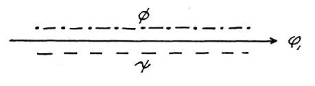
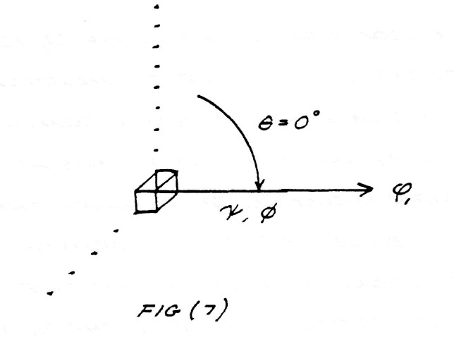
FIG (7)
This relation is called the axial product, often wrongly called the scalar product (The term dot product is often used). This form of electric induction is the longitudinal magneto-dielectric induction (L.M.D.) in contra-distinction to the transverse electro-magnetic induction of equation (1).
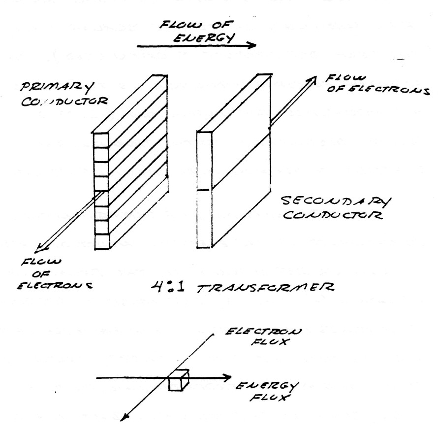
The dimensions of energy in this component of the electric induction are no longer represented by the relations in equation (6) and (9) but must be represented as a mass free energy. An example of this fact is that the L.M.D. energy propagates at right angles, or perpendicular, to the electronic flux, such as the mutual inductance of a transformer, being longitudinal in form, conveys energy from the primary coil to the secondary coil perpendicular to the flux of electrons in the coil conductors, figure (8)
FIG (8)
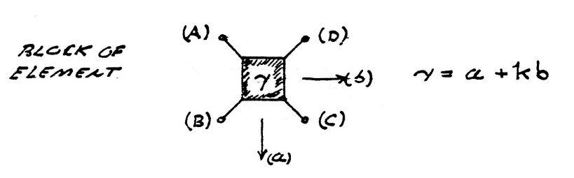
The symbolic expression of the total electric induction of a system of conductors is the complex sum of that percentage of induction contained in the transverse component
| $ a = sin \: \theta $ | percent | (11) |
and that percentage of induction contained by the longitudinal component
| $ b = cos \: \theta $ | percent | (12) |
hence, the complex quantity
| $ \gamma = a + kb $ | units | (13) |
The versor equation of electric induction is hereby given as
| $ \bar \phi = \gamma \phi_0 $ | (14) |
c) Product of quadrature conjugate inductions
The previous equations delt with the combination of a single magnetic induction and a single dielectric induction. However, in the windings of transformers and coils the magnetic and dielectric inductions consist each of two parts as described in part (a).
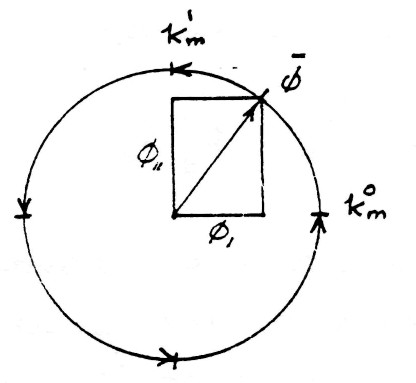
The versor relation of the complex combination of longitudinal (mutual) magnetic induction, and of transverse (leakage) magnetic indution is given by
| $ \bar \varphi = k_m^0 \varphi_1 + k_m^1 \varphi_{11} $ | (15) |
The geometric relations are given by the figure (9). The exponents 0 and 1 of index $k_m$ represent the amount of rotation around the magnetic reference axis $k_m$.
FIG (9)
Versor Diagram
Vector Diagram
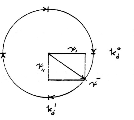
The versor relation of the complex combination of longitudinal (mutual) dielectric induction, $\psi_1$ and of transverse (leakage) dielectric induction $\psi_{11}$ is given by
| $ \bar \psi = k_d^0\psi_1-k_d^1\psi_{11} $ | (16) |
This geometric relation is shown by figure (10). The exponents 0 and 1 of index $k_d$ has analogous relation to $k_m$, that is, the amount of rotation. The minus sign indicate this rotation is backwards with respect to the magnetic rotation.
The total versor of electric induction is the algebraic product of the versor of magnetic induction, $\bar \varphi$, and the versor of dielectric induction, $\bar \psi$. Hence
| $ \bar \phi = \bar \varphi \bar\psi $ | (17) |
FIG (10)
Versor Diagram
Vector Diagram
and substituting (15) and (16) into (17) gives
| $ \bar \phi $ | $ =[(k_m^0k_d^0\psi_1\varphi_1+k_m^1k_d^1\psi_{11}\varphi_{11}) $ | |
| $ {}+(k_m^0k_d^1\psi_{11}\varphi_1-k_m^1k_d^0\psi_1\varphi_{11})] $ | (18) |
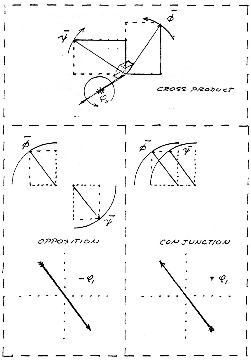
This equation is completely algebraic and therefor the order, or position, of the various terms is immaterial. This combination of inductions of various axes is shown by the figure (11)
FIG (11)
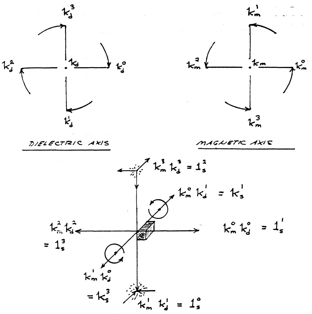
Quadruple Versor Product
The rules of multiplication for this quartic equation of four inductions,
and the four co-axial versor axes
is given as
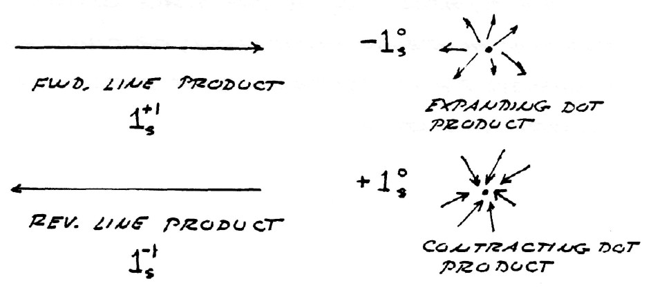
$k_m^0k_d^0=1_s^1$, longitudinal product
$k_m^1k_d^1=1_s^0$, scalar product
and
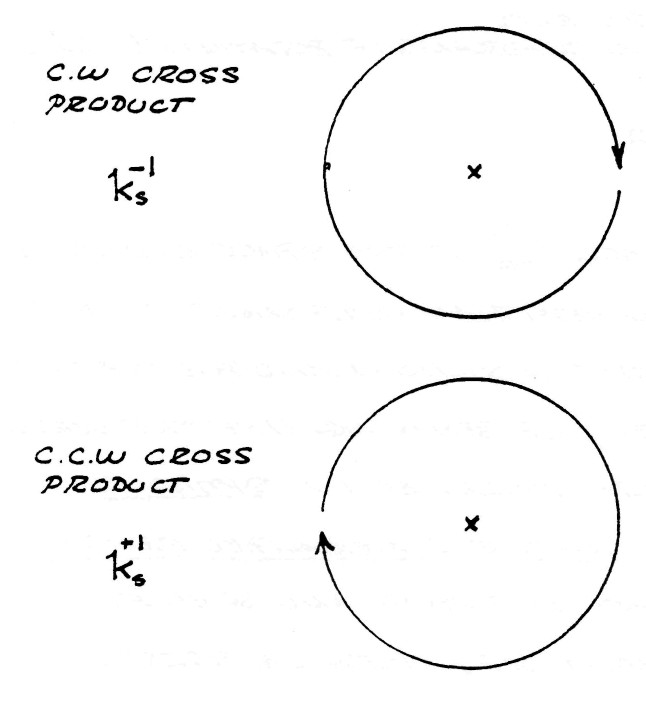
$k_m^0k_d^1=+k_s^1$, counterclockwise cross product
$k_m^1k_d^0=-k_s^1$, clockwise cross product
The symbols
$1_s^0=1$ represents a dimensionless unit
$-k_s^1=k_s^3$ represents two quadrants of rotation (180�)
(see figure 12)
The symbol $1_s^n$ is the space operator for the non Hertzian component of the versor of electric induction and posseses the unique property of behaving like the versor, or time operator, described in Symbolic representation of the Generalized Electric Wave, published by Borderland Sciences Research Foundation, Vista, CA. 92083.
The symbol $k_s^n$ is the space operator for the Hertzian component, or circularly polarized T.E.M. component, of the versor of electric induction.
FIG (12)
Substituting the values of the multiplication rules into equation (18) gives the symbolic expression
| $ \bar \phi $ | $ =(\varphi_{11} \psi_{11}+1_s^1\varphi_1\psi_1)+k_s^1(\varphi_1\psi_{11}-\varphi_{11}\psi_1) $ | (19) |
substituting
| $ \bar \phi_1 =(\varphi_{11}\psi_{11}+1_s^1\varphi_1\psi_1) $ | (20A) |
and
| $ \bar \phi_{11} =(\varphi_{1}\psi_{11}-1_s^1\varphi_{11}\psi_1) $ | (20B) |
gives the general expression of the versor of complex induction in a form similar to equation (5),
| $ \bar \phi=\bar\phi_1+k_s^1\bar\phi_{11} $ | (21) |
The multiplication of the four distinct inductions encountered thus gives rise to four distinct spatial distributions of electric induction:
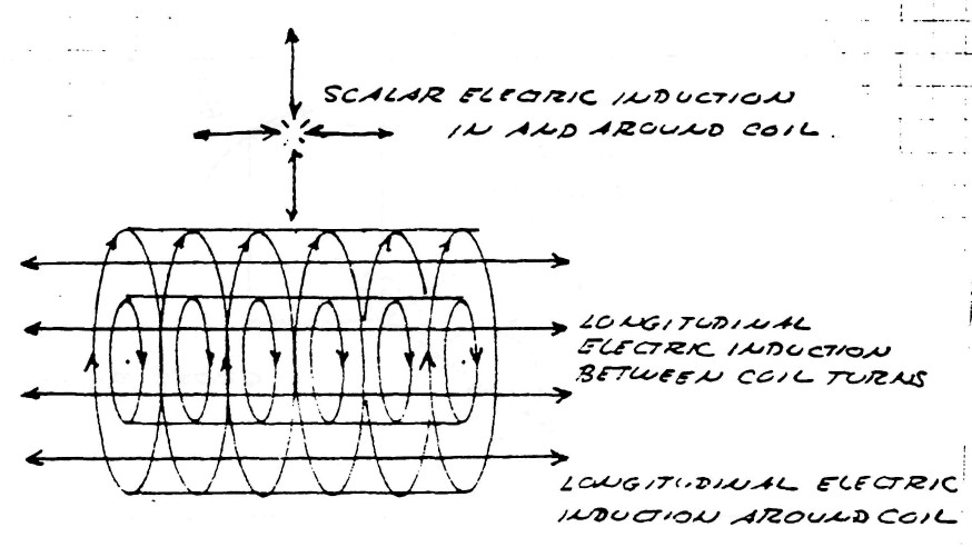
| $\varphi_{11}\psi_{11}$; Represents that component of the electric induction that is scalar in form, that is, exhibits no variation with respect to length or distance but is everywhere the same. |
| $\varphi_1\psi_1$; Represents that component of the electric induction that is longitudinal magneto-dielectric in form, that is, exhibits variation axially but not transverse to the direction of propagation along the transformer winding's axis. |
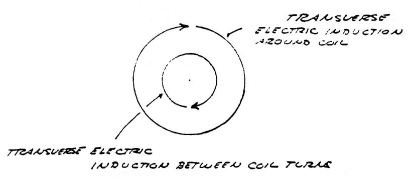
| $\varphi_1\psi_{11}$; Represents that component of the electric induction that is transverse electro-magnetic in form and is vertically polarized. This induction exhibits variation transverse, or perpendicular, to the transformer winding's axis, and passes thru the space between the conductor turns in a counter clockwise direction. |
| $\varphi_{11}\psi_1$; Represents that component of the electric induction that is transverse electro-magnetic in form and is horizontally polarized. This induction exhibits variation transverse, or perpendicular, to the transformer winding's axis, and passes thru the space around the outside of the winding in a clockwise direction. |
It can be seen that the two transverse inductions represent a pair of travelling waves moving in opposite directions around the winding.
While the scalar induction fills all space surrounding the transformer and does not propagate it does pulsate in time and therefor is not scalar in the dimension of time, but represents true L.C. oscillation of the transformer as a lumped circuit.
| $ LC=T^2 $ |
Hence, the complete transformer oscillation with spatial variation is given by
| $ (LC-u_s^2)=T_0^2 $ | (22) |
where $u_s$ is called the space constant.
The various inductions and there relation to the transformer winding are shown by figure (13)
FIG (13)
The transverse component of the electric induction is neutralized if the condition exists that
| $ \bar \phi_{11} = ( \varphi_1 \psi_1 - \varphi_{11} \psi_{11} ) = ZERO $ | (23) |
and therefore
| $ \frac {\psi_{11}} {\psi_1} = \frac {\varphi_{11}}{\varphi_1} $ |
hence
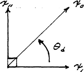
| $ tan \: \theta_d = tan \: \theta_m $ |
This is skown by figure (14)
FIG (14)
Alternatly, equation (23) becomes
| $ \frac {\varphi_1} {\psi_1} = \frac {\varphi_{11}}{\psi_{11}} $ |
That is
| $ Z_1 = Z_{11} $ |
The characteristic impedance of the longitudinal electric induction is equal to the characteristic impedance of the scalar induction.
In this case of neutralized T.E.M. the winding may be said to be distortionless, thereby producing an undistorted harmonic waveform in oscillation.
The non-Hertzian component of the electric induction is neutralized if the condition exists that
| $ \bar \phi_{1} = ( \varphi_1 \: \psi_1 + 1_s^1 \: \varphi_{11} \: \psi_{11} ) = ZERO $ | (24) |
which does not seem possible since the two terms must be complex quantities.
It should be noted that the presence of the conductor material serves to distort the distribution of induction because it excludes the magnetic induction by the production of eddy currents. For this reason the conductor material must be laminated in a fashion similar to that found in transformer cores, figure (15). Litzwire will serve as lamination in the winding of O.C. transformers.
FIG (15)
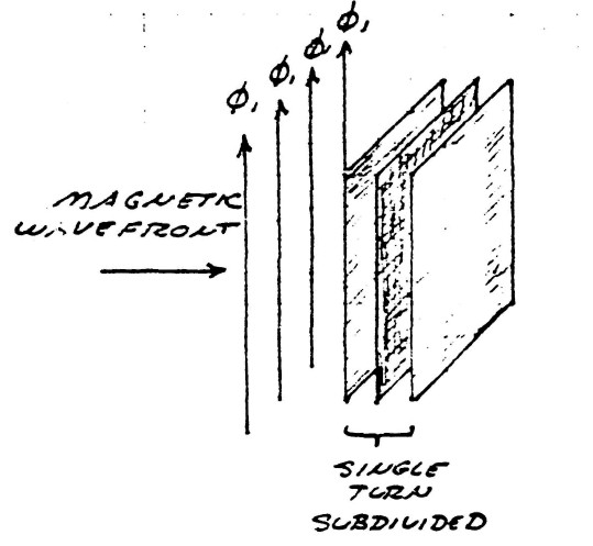
Thickness of conductor sheets must be less than 10% of the skin depth of ele ctronic conduction at operating frequency, or maximum harmonic thereof ($\approx 15 \: F_0$). For 1000 kc/sec (1 MHz) this is less than 0.001 inch.
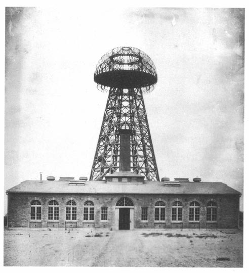
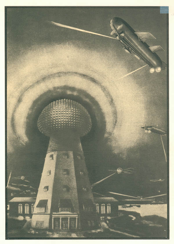
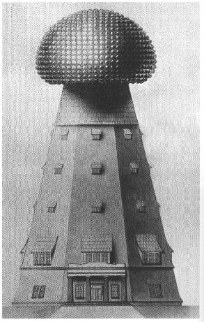
Some more Wardenclyffe tower pictures
The original one from this book: