
a) Product of conjugate pair of inductions
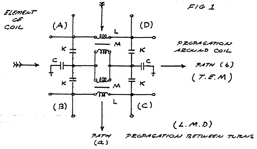
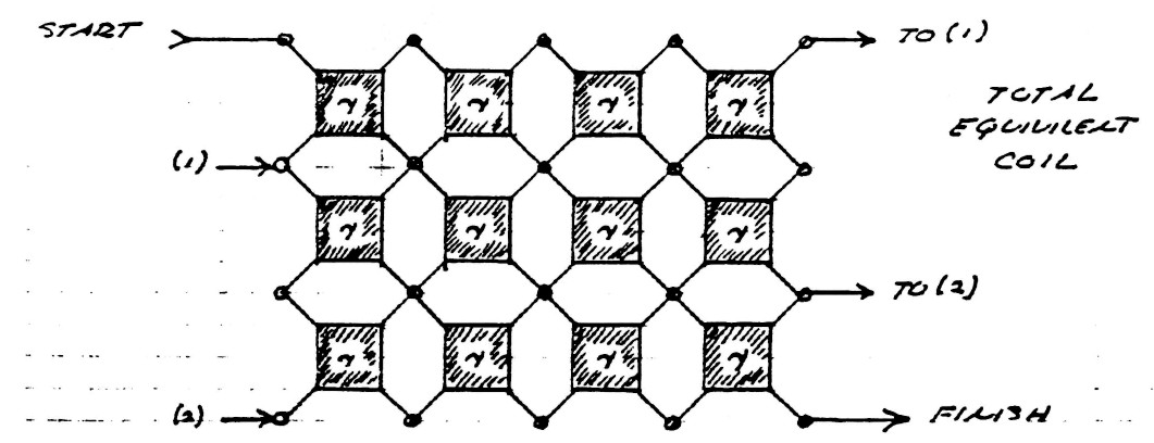
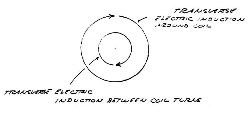
The wave theories in present usage for the study of electric propagation along coils and kindred apparatus all suffer from the fundamental drawback that they are representations of energy propagation along a single line or axis. The equivalent circuit of coil propagation is, however best presented as in figure (1), that is, two perpendicular paths for induction. Thus the propagation can occur in any direction on the surface of the mesh given by figure (1).
The nature of electric energy varies with the direction of propagation and departs significantly from the common electro-magnetic form when the path is no longer along the usual axis. This departure in form is of singular importance in the study of Tesla's discoveries.
FIG (1)
Since electric energy is the product in space of the flux of magnetic induction, and the flux of dielectric induction, the nature of these fluxes, and the nature of their products, determines the characteristics of electric energy that appear in the Tesla Oscillating Current Transformer. It is thus important to investigate the nature of these components of electric energy.
When electric energy exists in any system of electric "conductors" certain phenomena appear in the space surrounding the conductors, that is magetic and dielectric actions manifest themselves in the surrounding aether.
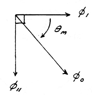
Surrounding the conductors s what is called the magnetic field of induction. The intensity of this magnetic field is given my the total number of magnetic lines, ϕ0, filling the surrounding space. The portion of the total magnetic induction which is parallel to the surface of the conductor is called the transverse magnetic induction, ϕ11, and that portion of the total magnetic induction which is perpendicular to the surface of the conductors is called the longitudinal magnetic induction ϕ1.
In general the transverse magnetic induction exists at right angles to the flow of energy and the longitudinal magnetic induction exists in line with the flow of energy. The geometric relations are given in figure (2).
FIG (2)
Issuing from the surface of the conductors is what is called the dielectric field. The intensity of the dielectric field is given by the total number of dielectric lines of induction, ψ0. The portion of the total dielectric induction that terminates upon surfaces in the direction of the flow of energy is called the longitudinal dielectric induction, ψ1, and the portion that terminates upon surfaces perpendicular to the flow of energy is called the transverse dielectric induction. The geometric relations are given in figure (3).
FIG (3)
The total magnetic field of induction, $\varphi_0$, and the total dielectric field of induction, $\psi_0$, together constitute the total electric field of induction, $\phi_0$, that is
| $ \phi_0 = \varphi_0 \psi_0 $ | Units of electric induction |
b) Transverse and Longitudinal components
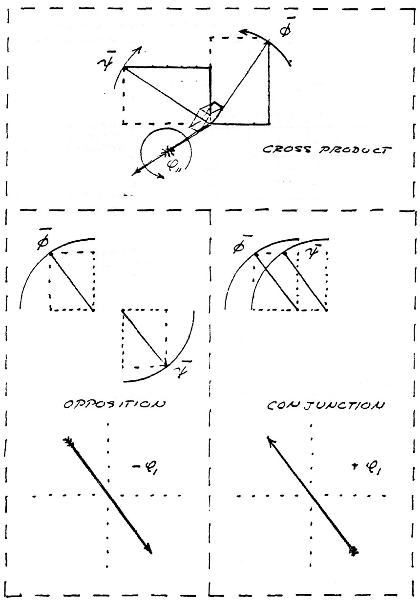
Transverse electro-magnetic waves, sometimes called Hertzian waves, are the result of the perpendicular crossing in space of lines of dielectric induction, $\psi$, and lines of magnetic induction, $\varphi$, figure(4).
FIG (4)
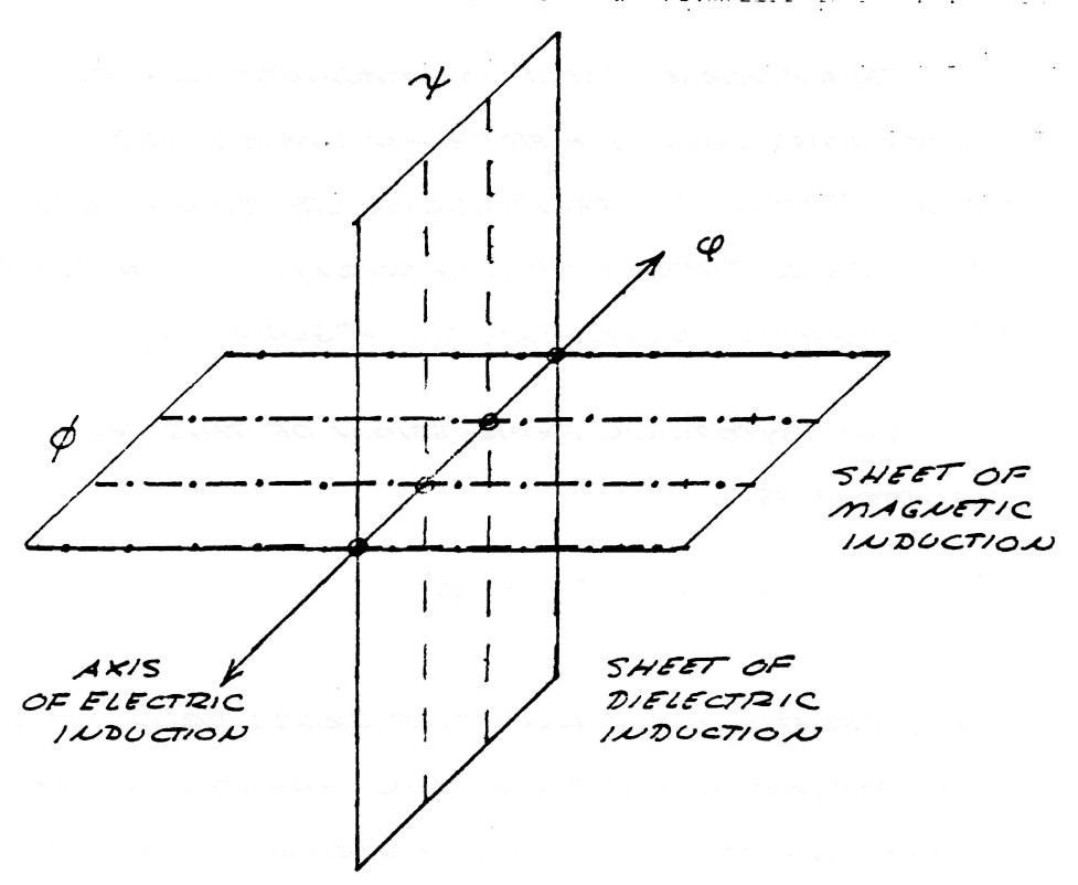
The symbolic expression of this geometric relation is
| $ \phi = \psi \times \varphi $ | (1) |
This relation is called the cross product of the magnetic and dielectric inductions that constitute the electric induction. This relation is the basis for what is known as the Poynting vector, first discovered by Oliver Heaviside.
The trigonometric edpression of this relation is
| $ \phi = \phi_0 \: sin \: \theta $ | (2) |
where $\theta$ is the angle of crossing betweeen the lines of $\psi$ and the lines of $\varphi$
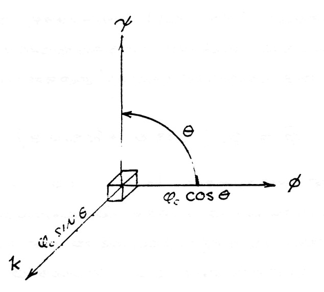
It was shown by Prof. Alexander Macfarlane in "The Imaginary of Algebra" presented before the American Association for the Advancement of Science, Vol XLI (1891-1894), that it is a general principle of spherical trigonometry that the complete versor expression of $\phi$ is
| $ \bar \phi = \phi_0 ( cos \: \theta + k \: sin \: \theta ) $ | (3) |
where the symbol k is no more than a distinguishing index indicating that the sine term is perpendicular to the plane in which the crossings of $\psi$ and $\varphi$ occur, figure (5).
By substituting the relations
| $ \begin{eqnarray} \phi_1 & = & { \phi_0 \: cos \: \theta } \\ \phi_{11} & = & { \phi_0 \: sin \: \theta } \\ \end{eqnarray} $ | $\Bigg \rbrace$ (4) |
FIG (5)
The symbolic expression of the complex induction is given by
| $ \bar \phi = \phi_1 + k \phi_{11} $ | (5) |
Hence, the flux of electro-magnetic induction is directed perpendicular to the inductions which give rise to it, propagating in the direction k.
The dimensions of electro-magnetiic energy are given by
| $\begin{eqnarray} W & = & m c^2 \\ & = & \begin{array}{cc} m \frac{l^2}{t^2}\end{array} \end{eqnarray}$ | Watt . sec (6) |
And the dimensions of magnetic flux are
| $ \varphi $ | $ = \frac{i}{W} $ | lines (7) |
| $ = \frac{l^2}{t} \frac{m}{\psi} $ | (8) |
Substituting equation (7) into (6) and substituting the law of dielectric induction
| $ i = \frac{\psi}{t} $ | lines/sec |
gives the dimensions of the transverse electro-magnetic induction as
| $ \phi_{11} $ | $ = m c^2 T $ | Watt . sec� |
| $ = m \frac{l^2}{t} $ | (9) |
where T is the time interval during which energy is exchanged between magnetic and dielectric forms of energy storage. The dimensions of equation (9) usually are given as the numerical quantity
| $ \phi_{11} = 6.6234 $ | $ x 10^{-34} $ | Watt . sec� |
or integer multiples thereof. This is usually portraid as a flux of these units of energy.time flowing along direction k, called a flux of photons.
The fundamental relation given by the equation (8) indicates that the electro-magnetic induction $\phi_{11}$ is only a partial component of the complete electric induction, $\bar \phi$, due to the existance of the complimentary component
| $ \phi_1 = cos \: \theta $ |
The geometric relation of $\phi_{1}$ is shown in figure (6). The lines of induction, $\psi$ and $\varphi$ in this case are in space conjunction and thus lay upon the same axis as the flux of electromagnetic induction $\phi$, to which they give rise.
Hence, a distinct form of electric induction totally unlike the electro-magnetic component $\phi_{11}$. The symbolic expression of this relation is
| $ \phi_1 = \psi \varphi $ | (10) |
FIG (6)
Conjunct Lines
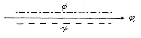
FIG (7)
This relation is called the axial product, often wrongly called the scalar product (The term dot product is often used). This form of electric induction is the longitudinal magneto-dielectric induction (L.M.D.) in contra-distinction to the transverse electro-magnetic induction of equation (1).
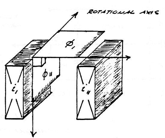
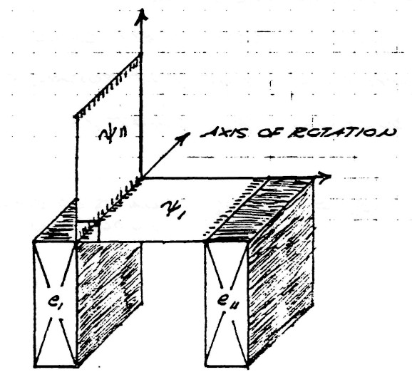
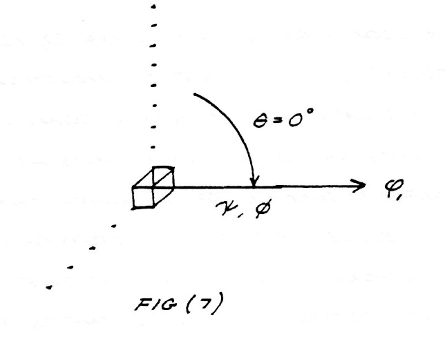
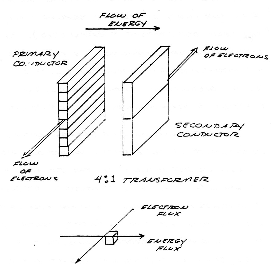
The dimensions of energy in this component of the electric induction are no longer represented by the relations in equation (6) and (9) but must be represented as a mass free energy. An example of this fact is that the L.M.D. energy propagates at right angles, or perpendicular, to the electronic flux, such as the mutual inductance of a transformer, being longitudinal in form, conveys energy from the primary coil to the secondary coil perpendicular to the flux of electrons in the coil conductors, figure (8)
FIG (8)
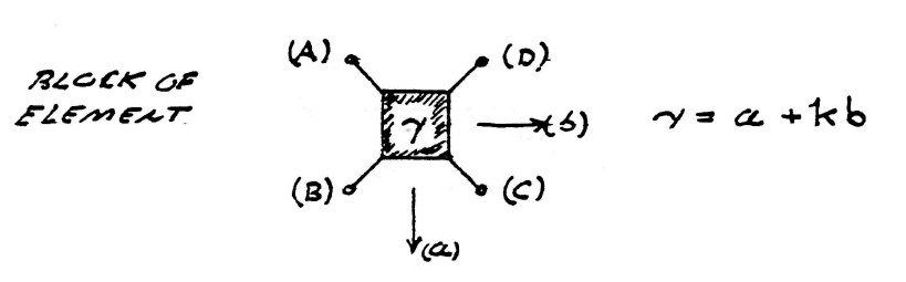
The symbolic expression of the total electric induction of a system of conductors is the complex sum of that percentage of induction contained in the transverse component
| $ a = sin \: \theta $ | percent | (11) |
and that percentage of induction contained by the longitudinal component
| $ b = cos \: \theta $ | percent | (12) |
hence, the complex quantity
| $ \gamma = a + kb $ | units | (13) |
The versor equation of electric induction is hereby given as
| $ \bar \phi = \gamma \phi_0 $ | (14) |
c) Product of quadrature conjugate inductions
The previous equations delt with the combination of a single magnetic induction and a single dielectric induction. However, in the windings of transformers and coils the magnetic and dielectric inductions consist each of two parts as described in part (a).
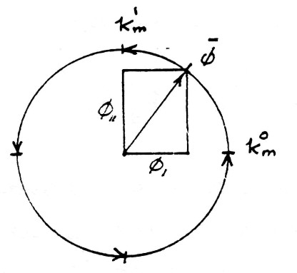
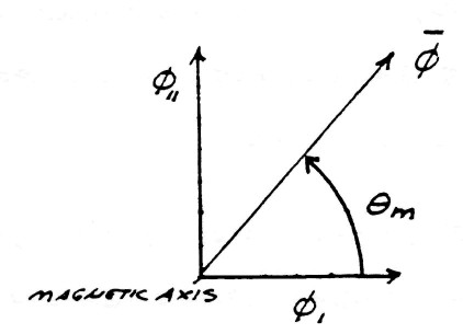
The versor relation of the complex combination of longitudinal (mutual) magnetic induction, and of transverse (leakage) magnetic indution is given by
| $ \bar \varphi = k_m^0 \varphi_1 + k_m^1 \varphi_{11} $ | (15) |
The geometric relations are given by the figure (9). The exponents 0 and 1 of index $k_m$ represent the amount of rotation around the magnetic reference axis $k_m$.
FIG (9)
Versor Diagram
Vector Diagram
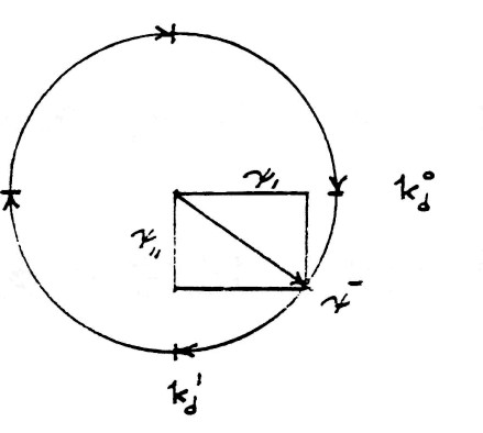
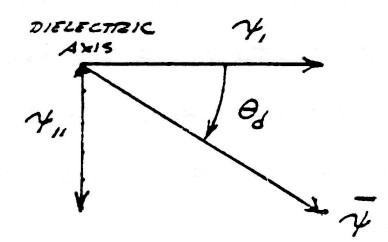
The versor relation of the complex combination of longitudinal (mutual) dielectric induction, $\psi_1$ and of transverse (leakage) dielectric induction $\psi_{11}$ is given by
| $ \bar \psi = k_d^0\psi_1-k_d^1\psi_{11} $ | (16) |
This geometric relation is shown by figure (10). The exponents 0 and 1 of index $k_d$ has analogous relation to $k_m$, that is, the amount of rotation. The minus sign indicate this rotation is backwards with respect to the magnetic rotation.
The total versor of electric induction is the algebraic product of the versor of magnetic induction, $\bar \varphi$, and the versor of dielectric induction, $\bar \psi$. Hence
| $ \bar \phi = \bar \varphi \bar\psi $ | (17) |
FIG (10)
Versor Diagram
Vector Diagram
and substituting (15) and (16) into (17) gives
| $ \bar \phi $ | $ =[(k_m^0k_d^0\psi_1\varphi_1+k_m^1k_d^1\psi_{11}\varphi_{11}) $ | |
| $ {}+(k_m^0k_d^1\psi_{11}\varphi_1-k_m^1k_d^0\psi_1\varphi_{11})] $ | (18) |
This equation is completely algebraic and therefor the order, or position, of the various terms is immaterial. This combination of inductions of various axes is shown by the figure (11)
FIG (11)
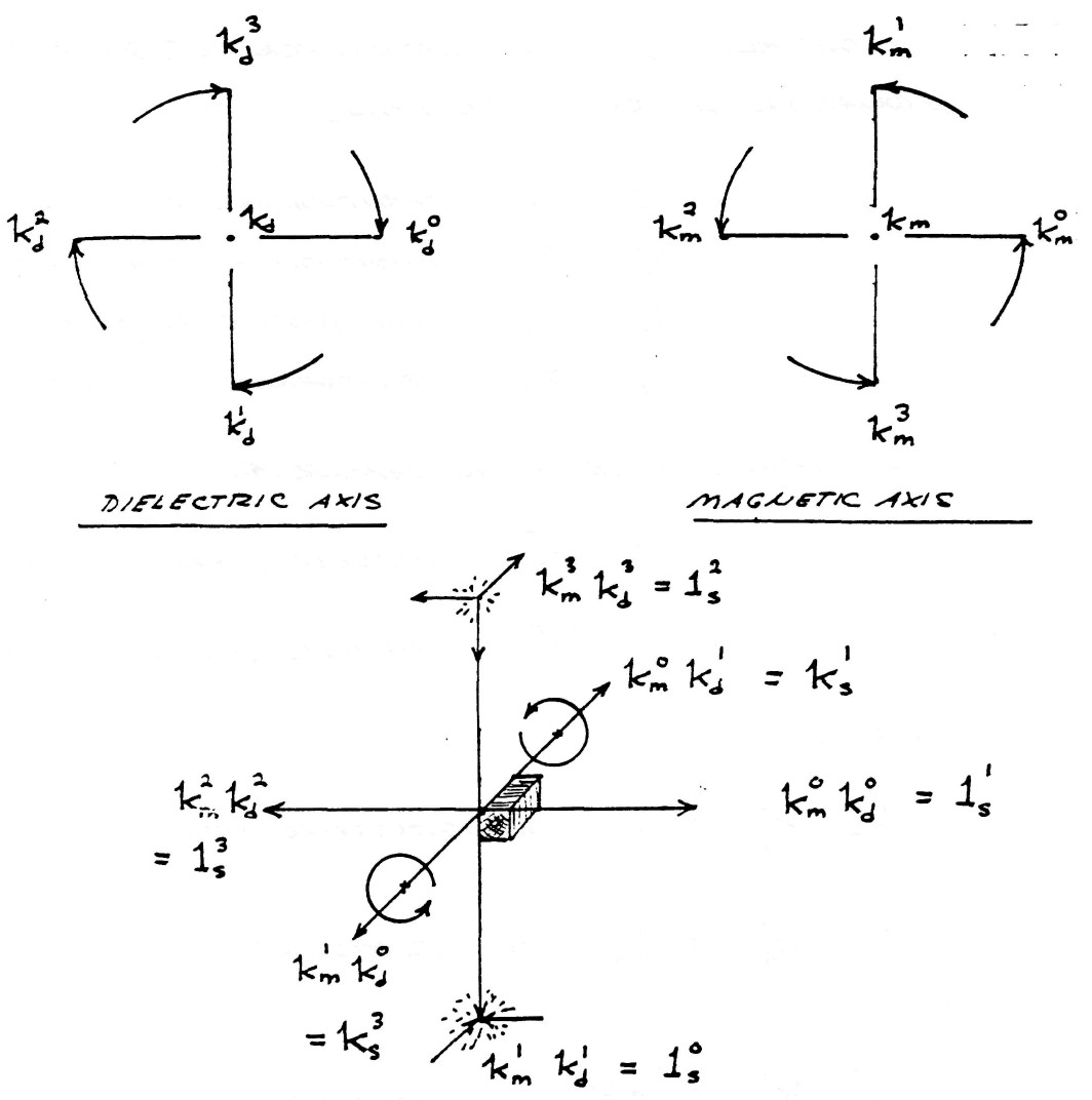
Quadruple Versor Product
The rules of multiplication for this quartic equation of four inductions,
and the four co-axial versor axes
is given as
$k_m^0k_d^0=1_s^1$, longitudinal product
$k_m^1k_d^1=1_s^0$, scalar product
and
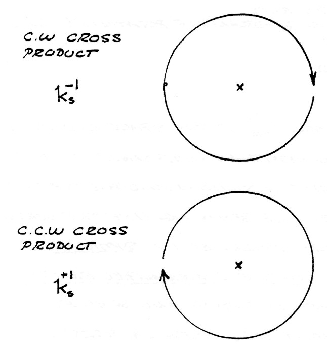
$k_m^0k_d^1=+k_s^1$, counterclockwise cross product
$k_m^1k_d^0=-k_s^1$, clockwise cross product
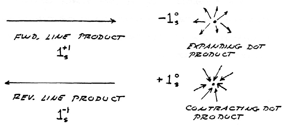
The symbols
$1_s^0=1$ represents a dimensionless unit
$-k_s^1=k_s^3$ represents two quadrants of rotation (180�)
(see figure 12)
The symbol $1_s^n$ is the space operator for the non Hertzian component of the versor of electric induction and posseses the unique property of behaving like the versor, or time operator, described in Symbolic representation of the Generalized Electric Wave, published by Borderland Sciences Research Foundation, Vista, CA. 92083.
The symbol $k_s^n$ is the space operator for the Hertzian component, or circularly polarized T.E.M. component, of the versor of electric induction.
FIG (12)
Substituting the values of the multiplication rules into equation (18) gives the symbolic expression
| $ \bar \phi $ | $ =(\varphi_{11} \psi_{11}+1_s^1\varphi_1\psi_1)+k_s^1(\varphi_1\psi_{11}-\varphi_{11}\psi_1) $ | (19) |
substituting
| $ \bar \phi_1 =(\varphi_{11}\psi_{11}+1_s^1\varphi_1\psi_1) $ | (20A) |
and
| $ \bar \phi_{11} =(\varphi_{1}\psi_{11}-1_s^1\varphi_{11}\psi_1) $ | (20B) |
gives the general expression of the versor of complex induction in a form similar to equation (5),
| $ \bar \phi=\bar\phi_1+k_s^1\bar\phi_{11} $ | (21) |
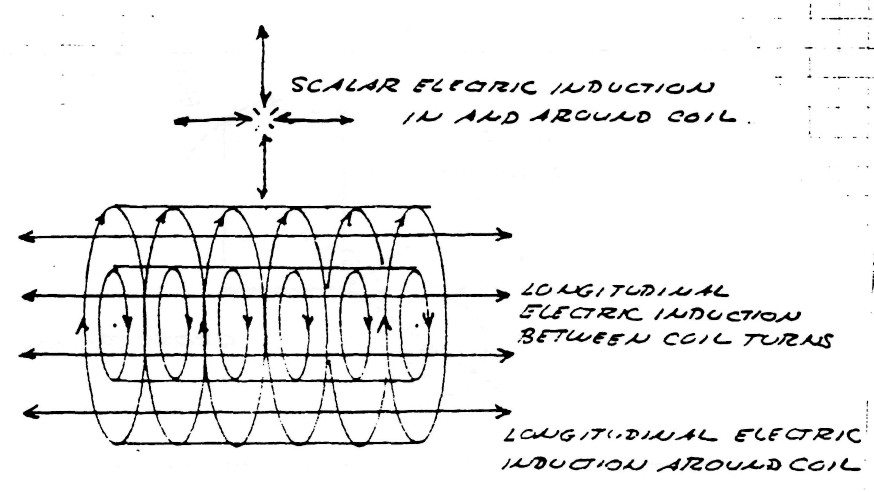
The multiplication of the four distinct inductions encountered thus gives rise to four distinct spatial distributions of electric induction:
| $\varphi_{11}\psi_{11}$; Represents that component of the electric induction that is scalar in form, that is, exhibits no variation with respect to length or distance but is everywhere the same. |
| $\varphi_1\psi_1$; Represents that component of the electric induction that is longitudinal magneto-dielectric in form, that is, exhibits variation axially but not transverse to the direction of propagation along the transformer winding's axis. |
| $\varphi_1\psi_{11}$; Represents that component of the electric induction that is transverse electro-magnetic in form and is vertically polarized. This induction exhibits variation transverse, or perpendicular, to the transformer winding's axis, and passes thru the space between the conductor turns in a counter clockwise direction. |
| $\varphi_{11}\psi_1$; Represents that component of the electric induction that is transverse electro-magnetic in form and is horizontally polarized. This induction exhibits variation transverse, or perpendicular, to the transformer winding's axis, and passes thru the space around the outside of the winding in a clockwise direction. |
It can be seen that the two transverse inductions represent a pair of travelling waves moving in opposite directions around the winding.
While the scalar induction fills all space surrounding the transformer and does not propagate it does pulsate in time and therefor is not scalar in the dimension of time, but represents true L.C. oscillation of the transformer as a lumped circuit.
| $ LC=T^2 $ |
Hence, the complete transformer oscillation with spatial variation is given by
| $ (LC-u_s^2)=T_0^2 $ | (22) |
where $u_s$ is called the space constant.
The various inductions and there relation to the transformer winding are shown by figure (13)
FIG (13)
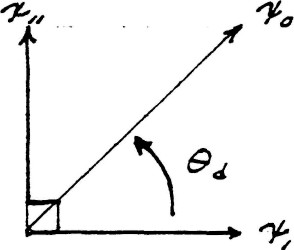
The transverse component of the electric induction is neutralized if the condition exists that
| $ \bar \phi_{11} = ( \varphi_1 \psi_1 - \varphi_{11} \psi_{11} ) = ZERO $ | (23) |
and therefore
| $ \frac {\psi_{11}} {\psi_1} = \frac {\varphi_{11}}{\varphi_1} $ |
hence
| $ tan \: \theta_d = tan \: \theta_m $ |
This is skown by figure (14)
FIG (14)
Alternatly, equation (23) becomes
| $ \frac {\varphi_1} {\psi_1} = \frac {\varphi_{11}}{\psi_{11}} $ |
That is
| $ Z_1 = Z_{11} $ |
The characteristic impedance of the longitudinal electric induction is equal to the characteristic impedance of the scalar induction.
In this case of neutralized T.E.M. the winding may be said to be distortionless, thereby producing an undistorted harmonic waveform in oscillation.
The non-Hertzian component of the electric induction is neutralized if the condition exists that
| $ \bar \phi_{1} = ( \varphi_1 \: \psi_1 + 1_s^1 \: \varphi_{11} \: \psi_{11} ) = ZERO $ | (24) |
which does not seem possible since the two terms must be complex quantities.
It should be noted that the presence of the conductor material serves to distort the distribution of induction because it excludes the magnetic induction by the production of eddy currents. For this reason the conductor material must be laminated in a fashion similar to that found in transformer cores, figure (15). Litzwire will serve as lamination in the winding of O.C. transformers.
FIG (15)
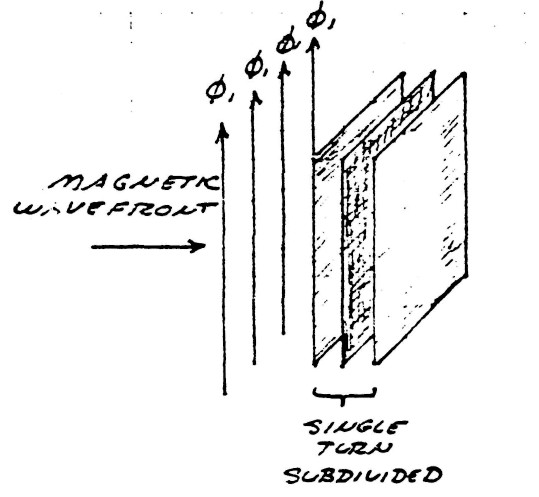
Thickness of conductor sheets must be less than 10% of the skin depth of ele ctronic conduction at operating frequency, or maximum harmonic thereof ($\approx 15 \: F_0$). For 1000 kc/sec (1 MHz) this is less than 0.001 inch.