
Collection of material by Matt Jones on the Tesla Switch
See: http://www.tuks.nl/pdf/Reference_Material/TeslaSwitch/
http://www.tuks.nl/pdf/Reference_Material/TeslaSwitch/TS_Guide_part_1.pdf
http://www.energeticforum.com/renewable-energy/962-use-tesla-switch-136.html
[...]
http://www.energeticforum.com/renewable-energy/962-use-tesla-switch-142.html
"Use of the Tesla Switch" thread on EF:
page 2
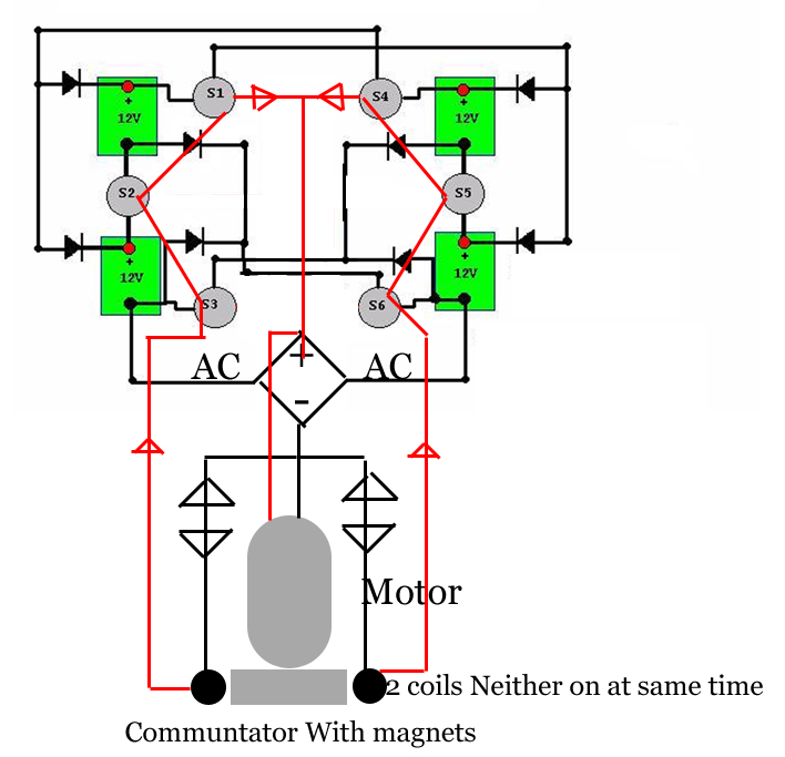
Maintains battery charge and delivers power on the shaft.
http://www.matthewcjones.com/power/TeslaSwitch_5_5.MPG
Matt
Sorry I didn't realize the lighting was that bad.
heres another. http://www.matthewcjones.com/power/TeslaSwitch_5_5B.MPG
8 12 volt batteries. 24volt system.
I'm gonna give more detail later. load tests, torque delivery,ect... I just wanted to encourage "wantfreeenergy". I wanna build a go cart with a bigger version. build your own four wheel bike or pedal car, plans and kits
Cheers Matt
Note: Appears to be available here: http://www.youtube.com/watch?v=Lw1Wcmm5I3w
As far as I can tell, there is no solid state way to create the switching action without sending current to ground. But... I am below a rookie when it comes to electronics, so I might be wrong.
I have looked at quete a few potential ways of doing it and all would require you to either generate energy to send to ground, like monopole, or send energy from your battery to ground. Neither one of these was acceptable to me.
I have drawn up plans for a low voltage control system with a mechanical communtator, that drives a high voltage relay system. You could use a real small motor to drive it and the bigger load would then pull off of the system at the rectifier.
Something like this would be optimal for say powering a car.
Matt
Well you might be able too. But I have not found a way to switch without sending to current to ground. Transistor has to ground. I believe 555 would ground at some point. I looked into a couple of other things off the top my head I can't remember what they were but they had ground. So... thats just what i concluded.
I might be wrong!! Electronics aren't my strong point.
If you know of way in which no current has to go to ground and you can switch a relay for instance then say the word. But I can't find one.
The only other thing you could do is use a transistor like a monopole does and generate your current to go to ground, but thats mechanical as well.
You might as well switch mechanically.
Remember if you ground any current at all you will lose. No chance of anything showing up, as far as extra energy. At least my belief and experience.
Matt
page 3
If you look at the load tests they check the batterries while running. And even while running the batteries continued to sustain or loose. Thats not to say they weren't conserving energy. Obviously they were.
The electrodyne report that used to be in the Practical guide to free energy (PGFE) stated that they had to add energy to the system on a regular basis. They also used the 6 switch version.
But... the originall circiut was 4 switch, according to the PGFE. With 4 switch's it is not possible to have a grounded circiut. No one has every came out and said it on this particular circiut but if you peice it together with the theories and working operations of other devices, then the conculsion should be obvious.
I wish their was solid state way of doing it.
Matt
Quote: With the relays, I was getting spikes over 100V at the bridge output, but the motor didn't seem to mind that at all
I have noticed that as well. A load, any load will only draw off what it can handle. You cannot force more current through it than it can take. On 24 volt system I can run a six volt load and runs exactly the same as it would if it ran off a six volt battery.
Theres somthing to that, I'm not sure what though.
Matt
I am pretty sure that same logic (on caps) does not apply to battery or a power source. 2 12volt batteries with 10 amp hour of energy, In Series will deliver 24 volt for 10 hours at 1 amp. You can test it. I have used the same formula to calculate expected discharge rates and seems to work out. I could be wrong according to the rules.
As far as amp draw in a Tesla switch you should be able to pull any load within the battery range. 17 amp hour battery should be able to deliver 17 amps of flow for 1 hour. If they don't deliver that you'll have to guage it for yourself how much you can pull.
I'm using lawn and tractor batteries, I have pulled some pretty big loads. The biggest thing that limits me is the heat from the bridge rectifier and the speed of the switching. The faster you switch the more power you have availible to you. Unlike a load a battery the load on the rectifier will reduce the voltage availible at the bridge and give a good indicator of how much more you can pull. 0 volts you have full load for your rectifier.
Also the component will only pull what it needs, you cannot force more through it, like hooking straight to battery. Thats a funny thing, but the best I can tell its the truth.
MAtt
Looks like actually the amperage to and accross the battery banks is higher do to the caps. Which would make sense because the caps are and easier load to fill than the batteries would be. Interesting stuff
Quote: I don't understand what you are saying here. Will you please restate or be more specific for me?
When you measure the voltage availible on the bridge rectifier (BR) it will go DOWN as you add loads. Normally a battery will drop but not like the bridge does in a Tesla Switch. Point being,(And this is just example from my head the numbers act differentk\ly) if you had say a 20 volt availible on the BR and added a 12 volt load, you might drop to 7 -8 volts. You could then add 2, 4 volt loads in addition and the BR would then read of 1-2.
The Voltage is incremental to the load that is on it.
You wouldn't usually see that the case of a power supply or battery. You would see an increase in Amperage from the source to the load but the voltage would remain the same, or slight variation on a battery
You'll find 12 volt lightbulbs don't really take 12 volt. Most I have used (Autobulbs) use about 3volt at 1/2 amp to run.
Its a neat thing to see. Matt
I have gone as fast as 200 times per second (hz). I don't use transistors though.
I would reckon that at some speed you will start hydrolisis on the battery. probably around 350 - 400. Not sure where it at though.
Where did you read JB say 10 - 20 switches per second? Could you point me to that?
Matt
ldissing:
Peter Lindemann said it on this forum or it is in the Mueller.pdf document in these forums. Just do a search for it.
I believe this is the link to the pdf.
http://www.energeticforum.com/renewable-energy/962-use-tesla-switch.html#post7525
Note: available in OCR-ed version here: http://www.tuks.nl/pdf/MUELLER_EXPERIMENTS_KROMREY_BRANDT_TESLA_BEDINI.pdf
The other link - > 100 hz for efficiency
http://www.energeticforum.com/renewable-energy/962-use-tesla-switch.html#post22489
--
@ldissing
I've read both those several times and have not run accross Bedini talking about the speed of the switching action in either one. In fact one was written by Patrick Kelly and the other wrote by Tom Bearden. Kelly mentions the electrodyne tests in an earlier version of DOC but they recomended No Higher than 200hz.
Also the AMP draw on a Tesla switch and Battery may be quete a bit different in the case of motor.
The reason primarly is the BEMF on the motor. When you ground a motor to run it both poles will create BEMF. This energy has to be disapated before current will flow. Reducing your actual flow time, and amount of flow. Also reducing the amount of energy actually doing work.
Running on a tesla switch you are only using either pole to run the load and nothing is grounded. BEMF is still being produced. but on a smaller scale and I suspect only on one pole. The pole that is opposite the polarity your on. So if you are running on the ground side of the battery the North pole attracted part of the motor is making BEMF. This is my Theory I am still building up for testing. A Unipole motor may solve BEMF all together.
I have seen limited amounts of this on my scope in one way tests. When watching the OUTPUT side of the motor on tesla switch you'll see 2 occilations. One is clear and obviously an ON/OFF wave. The other rises then falls but has both positive and negative spikes indacating BEMF. Depending on what side of the motor I power and what polarity of current I use the wave changes.
Also running test for the long term I have seen My batterries do not maintain the charge. I have 4 Walmart lawn and Tractors. Hook the motor up straight to the batteries (all 4) in parrallel the motor will run the batteries down in 56 hours. Thats from 13.00 volt to 12.00 volt. If I run the tesla switch till the batteries are dead (and they do die) it takes about 432 hours. Thats about 8 times longer of a run. I've tested the motor and gots docs on it its about 65% efficient when running under 12 volt. I figure if the Tesla Switch is allowing for 8 time more runtime then I am recollecting about 85 - 90 % percent of the energy, I'm passing through. I know batteries loose maybe 5% percent because they are lead acid. The rest is lost through BEMF in the motor. This is what I am attempting to solve NOW.
So back your question why 250ma one way and 500 the other. Well you have dramatically reduced the amount of BEMF in the way.
The reason it does not feel any more powerful is because of the same thing I do not beleive that Both poles in a conventional motor are doing a full amount of work. So the motor runs slower or less powerful.
Matt
I have tendancy to do that to people..
Quote: I assumed you are refering to back-emf as the induced voltage generated by the coils passing the stator magnets or the self inductance of the coils opposing the change in current as the coils charge (ie. not flyback voltage)
Thats some of Back EMF, but not all of it. After the motor switch's polarity in the coil, and starts to move away from the magnet (or stator), And is completly shut off, you still have charge on the wire. This charge is induced from the pulse of current to the coil. It very well the same thing you see in a bifiliar pulse motor with the secondary not on the power source. You know what I am talking about.
You probably watched this already, but this is the example of the energy I am talking about. YouTube - Simple Motor 2
What you call, FlyBack Voltage, is a bi product of BEMF. If you have flyback voltage it because you have BEMF on your coil, from the previous charging. The BEMF is charged opposite of the EMF and what would normally flow to ground now wants to flow to HOT and you have to disapate OR remove it from the coil, to get any work done.
Listen to the motor in the movie. When the spark stops, although I don't show it, amperage draw goes up, and the speed of the motor goes up.
Why? ............ No BEMF in the way.
This energy reduces the flow of current in a motor. That what I was trying to explain. Why his motor drew more amperage under a tesla switch than while running straight off a battery.
When I say pole I'm refering to the Coil. My mistake. I type faster than I think somtimes.
SO what I should have said is...
If you running a motor using a ground (Conventionaly) the energy flowing through the motor will create BEMF on both coils that are charged at the time. When they make it around the next charging position the energy has to be disapated before it will flow through the coil. Less tyime flowing equals less flow.
But in Tesla switch both coils do not produce adverse BEMF. Only one coil does. (My hypothisis still). Both produce extra energies that linger on the wire but one side is charged (do to the polarity of the energy you putting in) the same as the energy you are running through the motor. This energy can get swept out as the the current passes through and can be deposited into the charging bank. It does not get in the way.
But the other coil doesn't do this. It makes an energy that is polarized opposite than the energy you are putting in and therefore you have to disapate it before you get any work out of the coil.
The cause for this I have NOT fiugred out a good way to write. But the best I can say is when the energy you put in is from the NEGATIVE of your battery then repulses from the SOUTH magnet(stator) the byproduct energy, flows out nicely the next time the coil gets powered into the charging bank. Or maybe its opposite. I am not really sure about the finite details. But I know for sure its doing somthing like this.
Remember in most symetrical motors you have 2 poles (2 magnets) so one of your coils is charged to the south and one to the north while pulling into alignment then the polarity of your coils is flipped to push away. This is where the BEMF is created. The repulsion cycle.
If you have descent motor you should see on the scope what I have seen.
But I'll have to draw it for you from memory. I'll post it in the morning
I am packing to move to North Carolina. My scope and all my stuff got taped up an hour or so ago. I can hear it now , "Ya Right"
CHeers Matt
Quote: I was thinking about your getting 8 times the run length over a single battery. Actually, I think you'd have to say only 2 times as you are using 4 batteries total. Still, a nice improvement over a single battery. It is still not what we are looking though. Keep at it, you have still done a fine job.
4 batterries in Parrallel = 56 hours of runtime
same 4 batteries in a Tesla switch = 432 hours of runtime 432 / 56 = 7.714 times longer runtime.
Motor runs at or up to 100 watts AND PROVIDES SHAFT POWER.
Under Tesla the same motor only cost you 12.96 watts to get the same work done.
How much free energy do you want? And what the heck is it your looking for?
Me I'm trying to get off cheap. Maybe have a surplus in the end of somthing for free.
Gaurentee it don't get much better than that, unless you for some reason understand and can implement some high level physics.
Matt
Page 4
Quote: Using Matt's rotary switching is probably going to give the best results, but I am going to try an adaptation using solid state switching but combining what I have learned from previous experiments regarding charge conservation. Not keeping my hopes up as solid state is supposed to be less effective than mechanical switching, but it will be an interesting project.
You have to buy some real high end relays. Most mechanical relays don't go fast enough. These are about the best you can get with manageable size but they are ballpark $350+ for anything that will run a high amp motor.
Power Industrial Solid State Relays
I have found some on Ebay but they come from China (the supplier) and I just don't want to buy them. I'm not trusting at all even though they have a good rep. Solid State Relay SSR 24-220V DC, 40A + Heat Sink - eBay (item 230318896804 end time Jan-12-09 00:31:41 PST)
These are what I intend to buy for a vehicle setup. High Voltage Relays They are mechanical but they are fast.
Quote: In regards to mechanical switching.
You could setup a small trigger generator to drive the relays. Since its an either or setup timing would be the biggest thing. Both coils would have to be rather flat and the magnets would have to be small. But thats also extra energy into the system because you could Diode the energy into the bridge. It give you some options at least.
Matt
You could generate a trigger that could fire a transistor too. Just like a monopole. You would just have to diode 1 side of the coil with 2 diodes back to back. Use the other side of the coil to power the transistors at the base. You would only have to adjust the resistance on the base from the coil at that point.
See terrible quik drawing
Matt
Quote: No JB, no working device. And, I'm usually an optimist, but I've been working on a SS version for months and do not know if I'm any closer to it working than when I started. Am I even in the ball park?
Months??? And your already giving up? You get frustrated to easy.
Build a mechanical one first. I'm sure a solid state or a psuedo mechanical/solid state is the better way to go. It will work out sooner or later.
LOL freakin pitty party LOL
Matt
@ldissing
I read back through a ways in this post and I couldn't find where you mentioned what kind of transistors you were using.
I went back through JB's IceHouse site for the Tesla switch. The diagram there shows that he used SG1544 ocs transistor (http://www.datasheetcatalog.org/data...mi/SG1524.pdf). According to the data sheet can handle a fair amount of amperage. I would suspect that the transistor switches were comperable. In the Kromrey Brant/ Tesla switch paper (you'll have to find it) he uses n3055h ( http://datasheet.digchip.com/309/309-01824-0-2N3055.pdf ) which can handle up to 15 amps on the collector.
With the mechanical I had a big issue with the diodes. I was only pulling 2 amp yet I was popping 3 amp diodes like no tommorrow.
I suspect maybe some choking in your circiut, of course I can't test. Also I have noticed that in alot of specs for transistors and relays on an inductive load like a transformer or a motor that the amperage rating is reduce upto 1/3 its specs (IE a 2amp load needs a 6 amp or better rating in the transistor or relay). Why I am not sure, ask an engineer, or maybe you already know. If so I would like to hear about its.
Back to the diode issue I had. When I switched to 35 amp diodes the charging started. Now the batterries still consume over a long period but initially you would see them come oout off a load state and go to a higher voltage than they started at. Aty some point they would start to drop off again.
Thats why I would suspect choking. That and your motor you said does not run at full speed.
Load componenets do act different. Like I said before, you cannot force energy through them. But if you have a motor say, that should pull 1 amp and it is not pulling that then you have a choke point somewhere in your circiut. And in actual fact you should pull more amperage through your motor than its rated for. somewhere in the ballpark of 50% - 80 percent more do to the reduction in back EMF(Explained in an earlier post).
I still think its going to be hard to make complete solid state circiut. My hope, if I head that direction later is to do one with a mecahnical switching to fire relays. And hopefully use it in a green home to power loads like the lights or motors. This would help the efficiency if used in a solar powered home. I also think it could be used with AC as well. AC caps in line and the correct oscilation would allow the AC current to go much further than DC.
What ever you do don't give up. You get no where that way.
@nilrehob
You would better off to use the capacitors right in front of the battery, or between the battery and the circiut. 4 caps in total. Follow me? I'm not sure I how you are doing it now. But if you just use the caps inline to the load as diagramed by Patrick Kelly in the free energy guide you will have a greater loss. I'm not sure why. I know with just batterries I get about 80% recovery, on a one way setup. So it should be about that much when switching.
Lead acid battery efficiency is dependant on what kind of battery and what kind of component materials were used. They don't always just use lead in the battery. Some have different percentages of lead in the plates. Copper, ect...
You can test it though no matter what. My way is to watch what I get out of the charger and watch what sticks to the battery, over a given time period. If the charger is just straight DC with no pulse its real easy. Put an ACCURATE amp meter inline and reduce your end result by 2% or so. 2% is what the amp meter might consume.
And thats the other thing high voltage low amperage pulses stick to a battery better than say straight mix of voltage and amperage. So under these conditions a battery may become more efficient.
Thats one reason to use a load instead of a straight short . It helps you calculate how much is traveling through the system. You can then run the load right off the 4 batteries in parrallel and see the difference in how long and how hard they run. A good indication of how much more efficient the circiut is over conventional wiring. You can speculate the loss in the circiut after that.
I believe you will not find a conventional load that does not create loss. I think the whole design of electrical components anymore is based solely on the fact that they consume. Thats the engineering moto if you will. How can we consume this energy and make it work for us at low cost. Spread the consumption out through the circiut and send less to ground. OR somthing like that. Reguaging energy is not an option for them since its all a loss anyway.
Hope that helps. Sorry if I am rambling. Matt
Quote:* Inductive load to generate back EMF.
To the best I can tell you don't want this. If BEMF present in your motor (which it always is) you'll have a loss. I beleive it to be the biggest loss in my mechanical circiut.
I can't figure out how to link to one post in this thread but on page 3 I wrote down some theories I had on why this costs and what it is effecting in the circiut.
I built a small pulse motor that pulled the magnets (north to coil) in towards the coil then switched to north to push them away. Then it started all over. On the scope I got no signs BEMF. My points (I used auto points and a cam) were not sparking and little to no heat. I ran the circiut one way measure my run batts and measured my charge batts and gain 107% in my charge batteries. The point is the BEMF that was generated flowed with the current I was putting in, instead of fighting it. Regular motor won't do this.
Cheers
Matt
I don't get much out of a system while switching banks until about 160hz.
Like I said before on a one way test I can get 107% on average more out than in.
I think you need get rid of the caps and try some batteries with some sort of load.
I have at time hooked caps .5 farad 500 stereo caps inline with the batteries. They hold current real well and for along time (Days). I can then unhook them from the battery and my mechanical will run about 3 minutes before a noticable loss in power. So that alone is enough to say I am recovering.
I have yet to try it with my latest motor, and my stuff is packed for now until next month, but I beleive if I start switching with that motor, I'll go alot further. Caps probably need alot higher switching rate to maintian a charge or to invoke negative resistor effect on the capacitance plate. Unless your switching really fast (160hz - ???hz) you probably won't see anything but loss outa caps. But batteries.... well they are a different story.
I think probably Ideally you would not want the electron on the capacitance plate to not leave the cap at all, only jump one spot forward then back again. I don't know how fast that is though. I would guess you would develop alot of extra energy if you could make that happen. You might have a hydrolisis problem with a battery.
And yes reusing current is very possible. Grabing extra energy while doing it to recover your loss is also very possible. And I have proven it to myself. You'll have to prove it to yourself. Slow switching is not the answer.
Cheers Matt
More:
http://www.energeticforum.com/renewable-energy/962-use-tesla-switch-5.html
http://www.energeticforum.com/renewable-energy/962-use-tesla-switch-6.html
http://www.energeticforum.com/renewable-energy/962-use-tesla-switch-7.html
http://www.energeticforum.com/renewable-energy/962-use-tesla-switch-8.html
http://www.energeticforum.com/renewable-energy/962-use-tesla-switch-9.html
http://www.energeticforum.com/renewable-energy/962-use-tesla-switch-10.html
http://www.energeticforum.com/renewable-energy/962-use-tesla-switch-11.html
http://www.energeticforum.com/renewable-energy/962-use-tesla-switch-12.html
http://www.energeticforum.com/renewable-energy/962-use-tesla-switch-13.html