
The Electropolished WFC Replication Project
Report of project results
TODO: work this out;
Short outline: For this project, I received quite a lot of generous donations, for which I am still very thankfil. However, I feel, felt, like I let these people down.
And, in a way, I have.
Nonetheless, it were their donations, which made it possible at all to learn enough about Stan Meyer's WFC, that I can eliminate one possibility: electropolishing. That is: WITH A STANDARD ELECTROPOLISHING PROCESS
Also I got into quite a ride regarding my personal situation, like having to deal with being blessed and cursed with #autism (Asperger's).
So, I have been unable to report on my findings and keeping the project documentation up to date.
Fortunately, all this work did help to make significant steps in our scientific knowledge, so let's look forward instead of backward.
Thanks,
Arend Lammertink, MScEE.
Old page contents.
This project is aimed at providing experimental proof for my theory about Stan Meyer's "car on water" by means of building a working proof of concept prototype, based on one the most succesful replications thus far, the one by Dr. Scott Cramton. The most important change will be to exchange the standard RVS pipes with electropolished ones.
Now that I have received some donations and already covered the required funds, it is time to go from theory to practice and setup the project in such a way that as many people as possible can replicate this stuff.
This is a work in progress and the page is under heavy construction, so it's a bit shaky at the moment :)
I made a project directory at my server: http://www.tuks.nl/WFCProject/ In it, there is a preliminary shopping list made a couple of months ago for a friend of mine: http://www.tuks.nl/WFCProject/shopping_list.xls
And I started a thread at the open source energy forum for discussion and reporting about this particular project:
http://open-source-energy.org/forum/showthread.php?tid=1401
At the time of making the preliminary shopping list, we did not know of the electropolishing yet. The total amount for that was � 307,51, which was based on a Dave Lawton kit.
Because the Scott Cramton kit appears to be of a higher quality than Dave's, I want to go for that one.
Costs for a Cramton electrolyser kit without the tubes and a Dave Lawton PLL amount about EUR 295, excluding p&p. These are described further down.
There are quite a lot of quotes in this article.
Basic plan
The ultimate goal of this project is to replicate a production version of Stan Meyer's Water Fuel Cell, of which the design has surfaced and CAD drawings have been made of, which can be produced in Asia:

In order to be able to do that, an open source POC (proof of concept) is needed. So, the first goal of the project is to build something that works for as little costs as possible. The idea for that is to replicate one of the existing replications and replace the stainless with electropolished stainless, either by having standard tubes electropolished or by buying of the shelf electropolished stainless.
The first problem to solve is the most difficult one, which is to replicate the cell itself. When that is done, the engine will have to be chosen and it will have to be investigated what adaptions are needed to the engine. One particular problem with a lot of engines is the so called "waste spark" problem, which is caused by the fact that the timing of the engine will have to be adjusted for it to properly work on hydrogen gas.
Patrick Kelly described a lot of details in chapter 10 of his "A Practical Guide to Free-Energy Devices", which is hosted at my site:
http://free-energy-info.tuks.nl/Chapt10.html
In principle, both square plate electrolysers as well as tube based electrolysers can be adapted by exchanging the stainless for electropolished. Actually, Stan experimented with square plate versions first:

In Kelly's book, a number of successful replications are mentioned, which all use "conditioned" pipes. This is essentially a poor-man's version of electropolishing. Patrick writes:
Dave Lawton's replication can here be seen in action:
http://www.youtube.com/watch?v=vpu3zgSeLSo
Electropolished tubes
Electropolishing is a process used for passivating stainless steel. The big difference between other passivation methods and electropolishing is that it grows a much thicker layer of Cr2O3, which is an insulating dielectric layer with very similar properties as aluminum oxide used in most electrolytic capacitors.
It is possible to do this yourself, but the aim is to make use of off the shelf electropolished stainless, because the quality is likely to be higher and replications are also easier to make.
I have placed inquiries about the possibilites at a number of companies in The Netherlands. Ideally, off the shelf stainless is used and welded with mounting material, so the whole construction can be electropolished AFTER the welding work. However, off the shelf electropolished pipes can also be used, but then one has to take care of insulating the non-polished parts of the construction.
A company in the area has offered to do the electropolishing for friend's price of EUR 75,-. for my prototype. Replicators are on their own on this part.
That means we can do with the tubes kit offered by the same supplier, which are about EUR 450,-. for a set of 2x9 pipes (price listed on website is for just one set of two pipes, we need 9 of these).
The idea will be to first weld the mounting strips or threaded stainless rods to the tubes, before having them electropolished. For the construction, we consult Patrick Kelly's chapter 10:
Which tube to polish?
As I posted on the forum, there is a very important video made by Prof. Gerald Pollack, which actually (almost) explains how Brown's gas is being formed at the anode of our WFC and what Brown's gas actually is:
http://www.youtube.com/watch?v=eS4PkR_BkRo
While Prof. Pollack's work does not explicitly explain what Brown's gas is, his findings appear to be closely related to the research performed by Chris Eckman on Brown's gas, which you can find in this post.
Based on this material, we can deduce that a Pollack "EZ" layer is forming in the water, whereby we get a negatively charged zone or layer forming the interface between the metal/dielectric and the bulk water. Meanwhile, the "bulk" water becomes rich of H+ ions, thus becoming acid. This has been measured and shown by Prof. Pollack and is thus known to occur under certain circumstances. The most important criterium for this to happen is when a hydrophilic substance forms the boundary for the water, which can be as thin as one atomic layer thick deposited on some other material IIRC from Pollack's presentation.
Now this EZ layer is negatively charged, because it consists of ice-like honeycomb crystal structure whereby the H+ ions that bind the layers together are absent and have moved to the "bulk" water. Now when there is an electric field present, because of the positive plate being nearby, this positive charge attracks the negatively charged "EZ" chrystals, thus enabling the EZ zone to grow much thicker than without the presence of an electric field.
However, when you remove the positive charge on the metal plate (fast enough), you are left with a layer consisting of many many sheets of negatively charged crystalic structures, which repell one another. It does not take much fantasy to realize that this will not result in a stable layer, especially because the field of the (still) polarized dielectric, which has an opposit direction as the field which caused it, pushes the negatively charged crystalic structured layers away from the interface as soon as the charge on the metal plate is gone.
In other words: the negatively charged EZ layer is pushed by force into to "bulk" water by the polarized dielectric layer whenever the "capacitor" is discharged fast enough. And while we don't know how this works in detail, we do know what the result of this is: Brown's gas. And because we also know that these crystalic sheets consists of many, many atoms in alignment, it is clear that acoustic vibration is benifitial in breaking up these sheets, so bubbles of "Brown's gas" can be formed.
So, we get Brown's gas forming at the anode and up to a certain distance in the "bulk" water, when using pulsed D.C. to rapidly charge / discharge the capacitance formed by the metal plate itself.
However, we also get H+ ions in the fluid, which we need to get rid of. Fortunately, these are attracted by the negatively charged cathode, so it would be a good idea to have these pick up an electron, so H2 gas can be formed at the cathode.
This way, we get Brown's gas production at the anode and H2 gas at the cathode, provided the H+ ions can pick up an electron at the cathode. In other words: it would not be a good idea to electropolish the cathode, because that would make it more difficult for H+ ions to pick up electrons and thus would restrain the H2 gas production at the cathode.
And therefore I will only electropolish the anode and NOT the cathode.
Which tube should be the positive or anode?
Well, one can choose.
I was thinking of making the inner one the positive, but I haven't fully decided yet. It may be beneficial to take the outer tubes as positive, since these have a slightly bigger surface area. If you want a visible glow, then you would want to take the outer tubes as anodes, which *might* also show the glow at the outside. Might be cool, especially in a demonstration unit as I am planning to build. :)
Lawton used the outer tubes as positive and connected all the inner tubes together as cathodes, according to Kelly's:
http://free-energy-info.tuks.nl/Chapt10.html
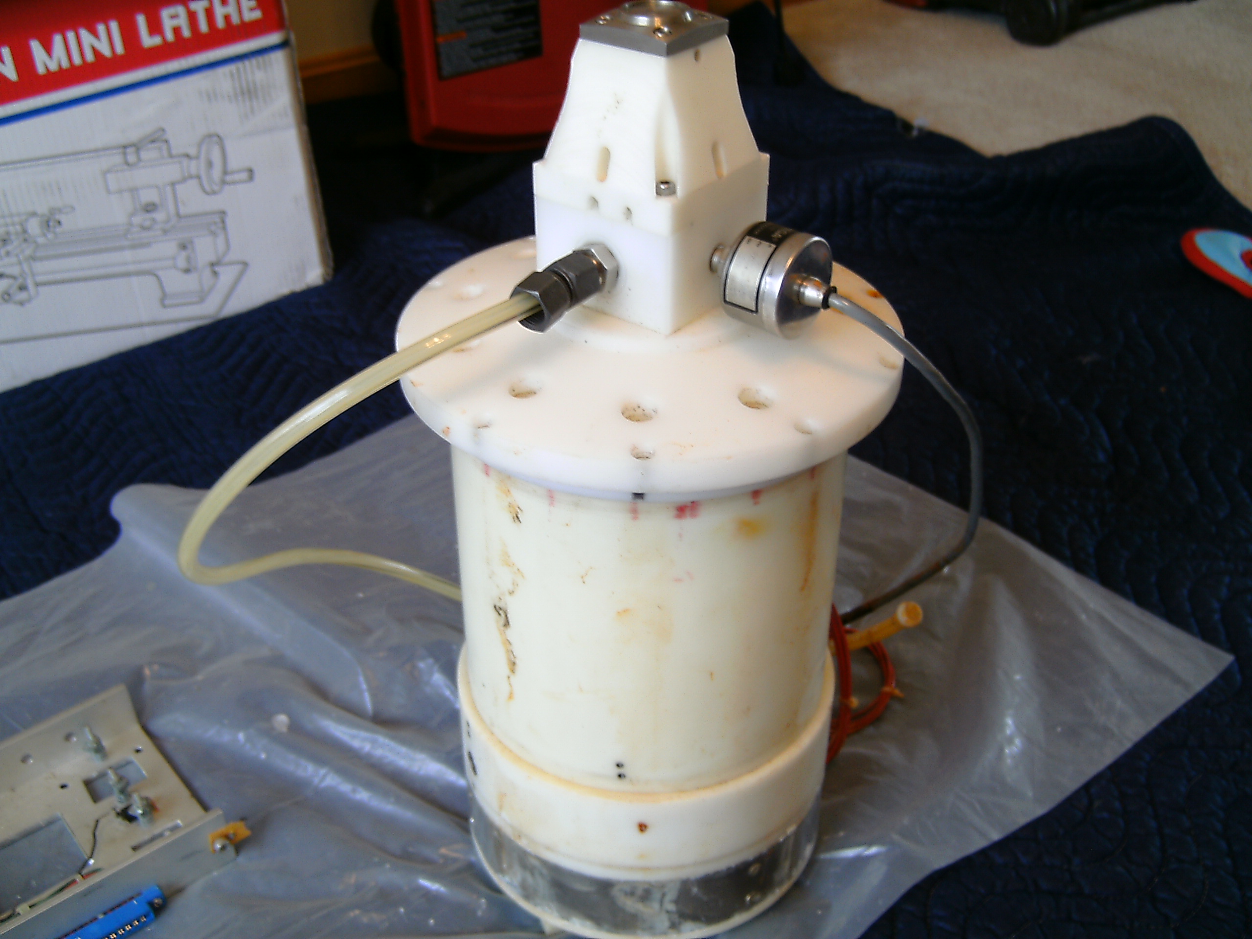
Cramton did it the other way around and just wired all outer tubes together:

With the Cramton kit, one will have to drill and tap the outer tubes, which will have to be done before the electropolishing for optimal results. So, when using off-the-shelf electropolished, one might opt for using the inner tubes as positive. OTOH: one will need to make a connection and some support either way, so the small holes filled with nylon bolts might not be such a problem too. In the case of using off-the-shelf electropolished, one might consider insulating the contacts with some epoxy raisin or something anyway.
I was thinking of welding a threaded stainless rod to each tube before electropolishing, so the tubes have support at the bottom and each electrical connection is taken to the outside individually. This makes it possible to place the tubes in series, as Stan also did:

It will also allow experimenting with two or three phases, such as Cramton did.
So, I think I will take the outer tubes as positive/anode, because I'd love to observe "the glow". :D
Electronics
For the electronics, Dave Lawton kits are very attractive, because there is one with PLL auto tuning feature, which is needed to maintain the acoustic resonance of the cell. Two versions of his electronics are available, though:
1) The Dave Lawton PWM PWM (pulse widh modulation) Kit;
2) The PLL auto-tuning kit, which can also be manually controlled.
One can choose for full kits, just the PCB, or a PCB kit.
Both of these require coils, which means we also needn at least one of these:
For experimenting with this, one can consider to take a few more of these.
This is the schematic of the PLL kit:
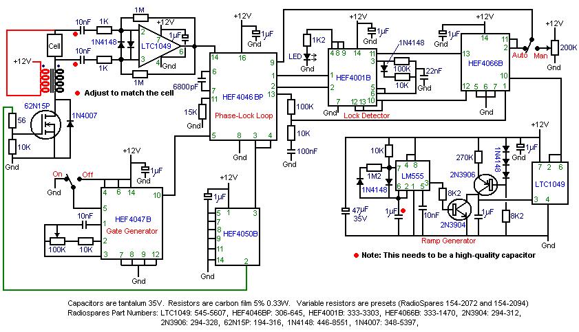
On this YouTube video, it is said that it is a good idea to replace the 200V mosfets with 600V ones:
http://www.youtube.com/watch?v=vhT9oF_2kek
In the video, they used a SPW47N60C3. I can't find that exact one at my supplier, but they do have the SPW 20 N 60 S5 N-channel, which is 20A instead of 47A.
I am also considering the STP 80 NF 10, which has an RDS(on) of 0.01 Ω, while being capable of handling 80A at 200V.
Diode placement
In the Dave Lawton circuits without PLL, the diode around the Mosfet is shown to connect to 12V to which also one of the coils is connected, while in the PLL circuit shown above it is connected to ground:
In the arrangement with an alternator also diodes are employed in a similar way. I suspected the diode needs to be in the position as in this picture, which makes sense because then it would allow the coils to discharge into the cell, so I asked Patrick Kelly, who replied:
Consider this schematic of a Bedini "Schoolgirl" variant, which is similar to our Mosfet driving circuit:

This circuit generates "spikes" with considerable voltage and Bedini calls these spikes "radiant energy", which he uses to charge batteries. If we add this extra diode to the PLL circuit, we not only protect our mosfet for high voltages, but we also enable the coils to discharge into the WFC. And then, we can opt for a pretty low voltage rated mosfet, which are much cheaper.
Electrolyser Kit
The easiest way to make a cell is to use a kit. The one by Scott Cramton appears to be very complete indeed. All that is missing is the tubes:
Scott Cramton Complete Electrolyser Kit consisting of the 1 x 150 x 750 x 3mm acrylic tube, 2 x HDPE end plates, 2 x tube mounting plates, 2 x gaskets, 1 x SC Plastic Fitting Kit, SC Fixings Kit, 4 x 1mtr x 10 studding bars, 16 x 10mm nut and 16 washers.
This is what the kit looks like:
Feasibility of running a small 1 cylinder engine on the proposed cell
For an estimation of the feasibility of running a small engine on the proposed Cramton replication kit, we consult Patrick Kelly's Chapter 10:
[...]
[...]
Since we are building a Cramton replication with electropolished tubes which should at least perform equally well, we should be able to produce at least 6 lpm of gas for an input of less than 100 Watts, which should be more than sufficient to run a generator of over 5 kW under load. My generator is about 2.5 KW and my lawn mower engine is comparable in size, so it appears to be totally feasible to run one of these engines on the proposed Cramton replication kit.
Note that these numbers are related to HHO or Brown's gas systems, whereby addition of water fog to the gas mixture helps the burning process. We don't know yet for sure whether or not the electrolyser will produce H2/O2 gas or Brown's gas, or a mixture of the two. While in main stream science Brown's gas or HHO, as it is most commonly known, is ridiculed, this is a real phenomenon. See the "update" section in my article for more information.
However, this should not be any problem. For now, I assume that the electrolyser will produce a mixture very similar to the other electrolysers described by Patrick Kelly, who also describes exactly what needs to be done in order to run an engine on the gas produced by most electrolysers, which comes down to mixing the gas with "cold water fog":
What is needed to make this work in practice?
As I posted on the forum, I have been lucky enough to be in contact with Frank Collaris, who did a lot of research on how to run engines on "brute force electrolysers". There's an article out in Dutch now about him and his company and there are quite a lot of people involved within and around his company. One can use Google translate to get a rough translation in English of the whole article.
I hand edited some of the more interesting parts:
[...]
As is stated in the article, the first commercial system is not yet ready. Frank has done a lot of research on this stuff and he told me he needed about 6 kW of input power for the system mentioned in the article. He started with a small generator, which I have seen running on water gas two years ago in April 2012 at a free energy gathering in France, where we both attended and spent a couple of days together, although there was no closed loop or any demonstration of excess energy at the time.
In May 2012, they were to demonstrate their stuff, but quite a lot of things went wrong and the demonstration was, well, a disaster. The original critics site appears to be down, but I have a mirror.
Needless to say, Frank became a bit more careful with his communications with the outside world, as was also mentioned in the article above:
To come back to the question: What Frank and his team did was to make an existing (old) generator with a Mercedes engine completely computer controlled. Not only the ignition timing, but also the control of the electrolyser and water fog system. This enabled them to do a lot of experiments on-the-fly with a running system and also allowed them to tune the system to the application.
When we are talking about these kinds of "brute force" electrolysers, both the voltage and pulse frequency applied influence the kind of gas being produced. While we do not yet fully understand the exact physics involved, we do have enough evidence to support the hypothesis that HHO or Brown's gas is a phenomenon whereby water is transformed into a form consisting of crystalised sheets with a honeycomb structure, very similar to ice BUT without the H+ ions which bind the crystal sheets together as in ice. We also have reason to believe that the formation of gas bubbles somehow containing this particular shape of water involves the formation of a Pollack "EZ" zone, characterized by a negatively charged region forming the interface between the positive plate and the "bulk" water within the electrolyte.
The voltage across this "EZ" region appears to be a very important parameter controlling the thickness of this layer, because of the electric fields involved. It also appears that when the voltage across this interface is suddenly removed, we are left with an EZ layer which is unstable because the negatively charged crystal sheets repell one another. It appears that pulsed D.C. across this interface at the anode is the main mechanism for creating this "Brown's gas" which has a number of very strange properties, while acoustic resonance of the fluid column in the electrolyser adds additional instability to this EZ layer and thus appears to also influence the amount of Brown's gas being produced.
Besides this phenomenon, there is a considerable current being driven trough the electrolyte, which appears to be responsible for the creation of H2 / O2 gas along the normal electrolysis process.
So, you end up with a system that has a number of parameters which can be used to control the type of gas being produced:
1) Voltage across the plates. Higher voltages than 2V appear to increase the amount of H2/O2 gas formed along normal electrolysis, while voltages around 1.8V per cell appear to result in mostly Brown's gas being formed.
2) Total current trough the system. More net current trough the system appears to increase the amount of H2/O2 gas being formed along normal electrolysis.
3) Pulsed D.C. appears to enable the production of Brown's gas. The pulse width, on/off timing and frequency appears to control the thicnkess and instability of the EZ layer and thus influences the amount of Brown's gas being produced.
4) The frequency of the pulses also appears to connect to acoustic resonance of the fluid column in between the electrolyser plates and thus appears to influence the amount of Brown's gas being produced indirectly.
So, controlling and tuning all these parameters make it possible to control the quality of the gas being produced by the electrolyser and adapt this to the application, which is also what Frank has done.
And these are only the parameters related to the gas production. Other parameters which also need to be controlled are:
1) ignition timing (and "waste spark" suppression when applicable);
2) amount and quality of "cold water fog" injected into the air stream.
There appears to be a difference between "fog" and "mist". I haven't looked at this in detail, but the size of the droplets being injected appears to be yet another parameter which influences the result.
To cut a long story short: just about every parameter you can think of has to be made adjustable and then one can tune the system to find the "hot spots" which give the desired results. For each of these parameters there appears to be an optimal setting. Get one or two of these too far from their optimum in your particular system and you can forget about getting a working system.
Tuning of the pipes necessary?
Patrick Kelly stresses that it is necessary to tune the pipes in a Lawton/Cramton type of cell:
However, I don't believe that is necessary, because it's the fluid which is supposed to vibrate and NOT the pipes themselves, just like it's the air that vibrates in an organ pipe or an oxen horn (the instrument I "play") and NOT the instrument itself.
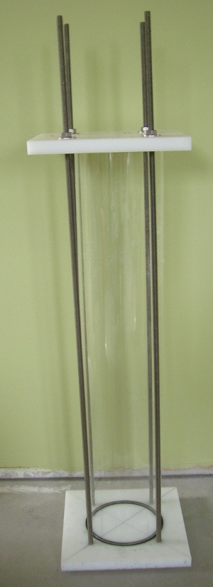
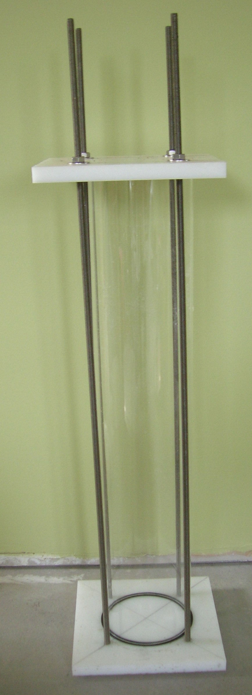
And even when tuning of the pipes themselves would be helpful, the fact that Cramton's pipes are put into place holders after tuning, which restricts the tube's vibration and thus changes it's resonance frequency, would totally ruin the whole tuning effort.
So, because Cramton's cell worked fine, even though he tuned the pipes "in the air" before mounting which would be totally useless because of the mounting of the pipes in place holders, I am pretty sure there is no need at all to do so. So, I disagree with Patrick in this respect.
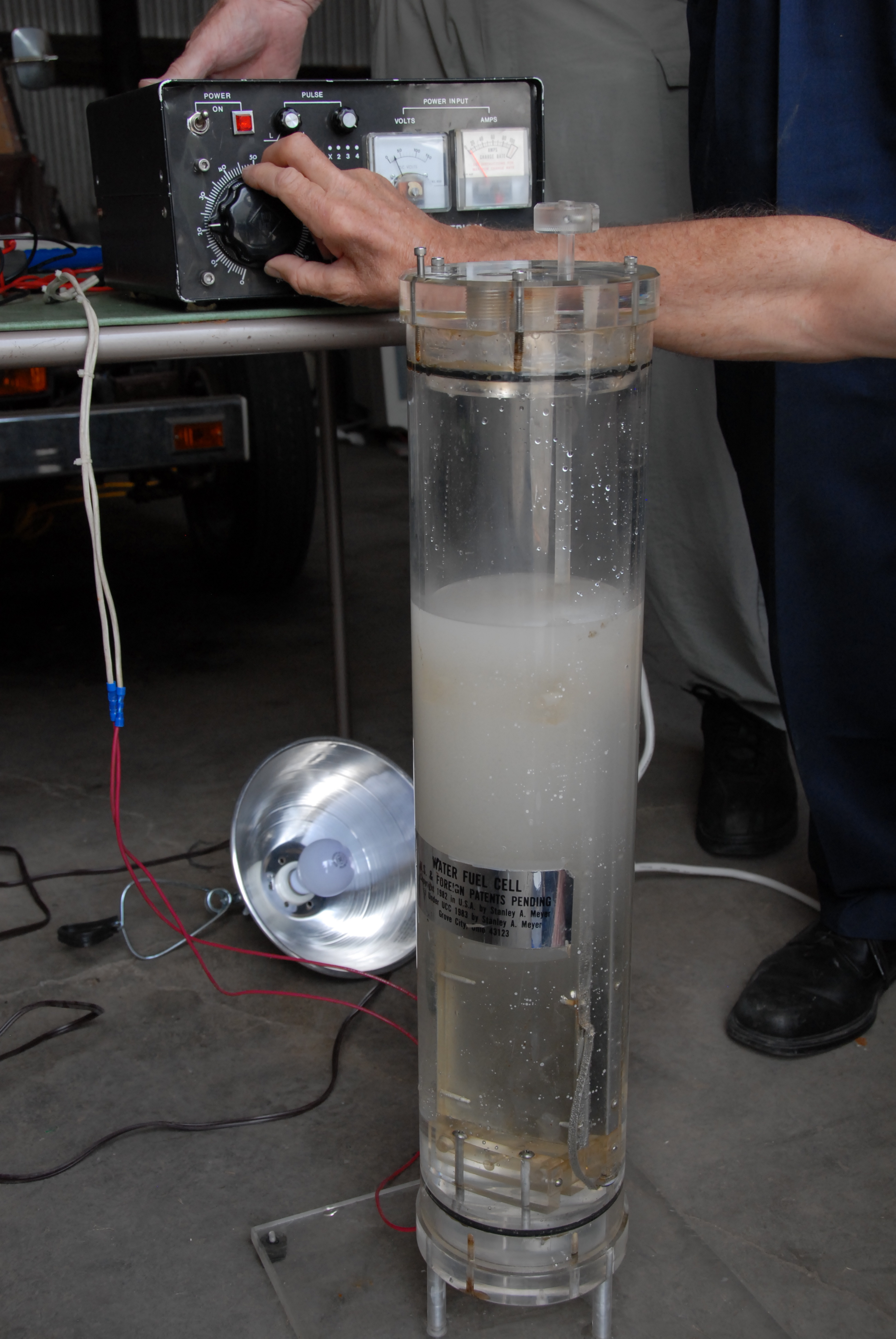
Also consider this image, wherein you see this PLL circuit along with a test cell in the upper part of the picture:
http://www.free-energy-info.tuks.nl/Chapt10.html
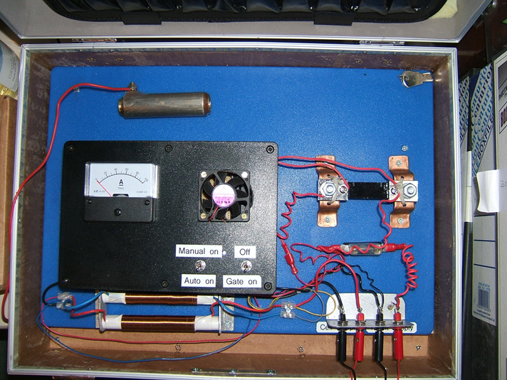
The video shows that it works just fine without any tuning of the pipes whatsoever:
http://www.youtube.com/watch?v=XMizRAYdGwA
To me, that makes it pretty clear that the tuning method proposed by a/o Kelly is most likely a total waste of time and effort. Just make sure the length of the fluid column in the pipes is the same for all pipes and it will be just fine, as far as I can tell.
Engine and modification
Engine 1
I first intented to use my old lawn mower engine, which I intended to equip with an automotive alternator. The engine I intended to use is a Briggs and Stratton Quantum 35, which is rated 3.5 HP or about 2.6 kW:
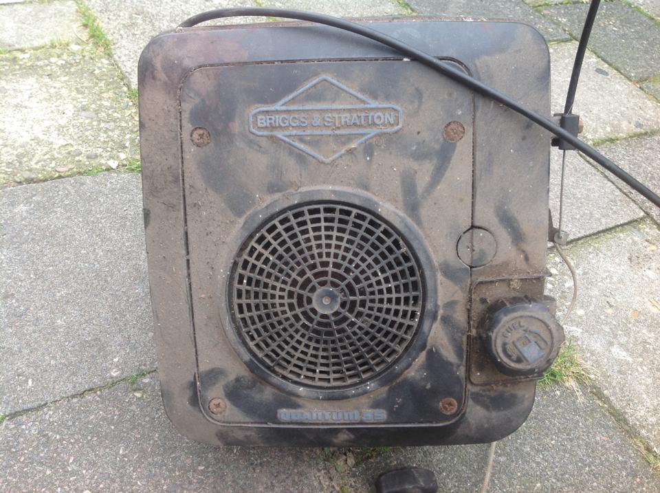
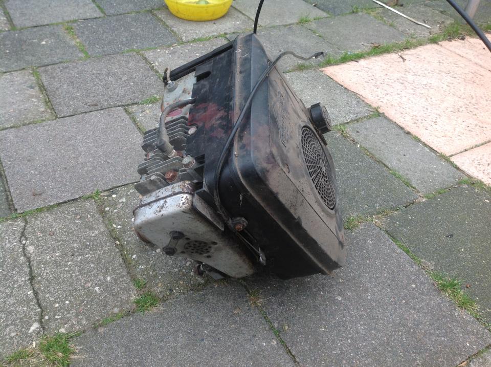
More images here
Some diagrams about this engine can be found here and here. The engine is equipped with so-called Magnetron ignition, a solid state ignition system without contact breakers, further explained here. The ignition modules are still available.
From these diagrams it became clear that this engine is a so-called flat-head engine, whereby the valves are placed alongside the cylinder, which makes it pretty challenging to get rid of the waste spark problem. Irondmax posted some video's about this, wherein he shows a construction with gears and a chain:
http://www.youtube.com/watch?v=X9qtCWyxwng
This one shows the valve timing of a Briggs and Stratton engine:
http://www.youtube.com/watch?v=iu9LosA7s8c
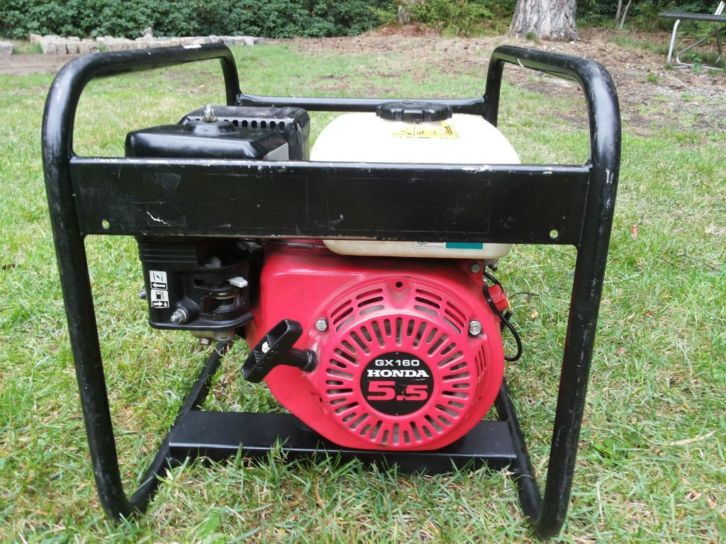
Change of plan - a Honda engine
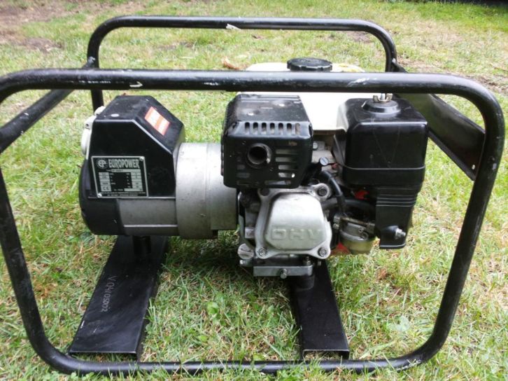
Because of the waste spark problem and the fact that an automotive dynamo needs a considerable steering current for voltage regulation, which means it can't run without a battery, I decided to look for a reasonable used Honda engine with overhead valves (OHV). I have picked one up in the area, complete with generator:
For these, it is relatively easy to get rid of the waste spark problem:
http://www.youtube.com/watch?v=UfGRPJWOGvo
http://www.youtube.com/watch?v=JomHUdpQbvw
With this engine, the waste spark problem can be tackled much easier, and the generator can deliver output without the need for any battery, which means it should be possible to eventually self-run the system without a battery connected to the system.
Engine adaptions
The engine itself will require a number of adaptions, which have been described by Patrick Kelly in detail:
http://free-energy-info.tuks.nl/Chapt10.html
One of the most important adaption to the engine itself is to adapt the spark timing and suppression of the "waste spark". Another important ingredient to the system is the mixing of "cold water fog" with the gas.
Kelly's "manual" includes a section "Running an Electrical Generator without Fossil Fuel", which explains the theory and basic steps:
Getting rid of the waste spark
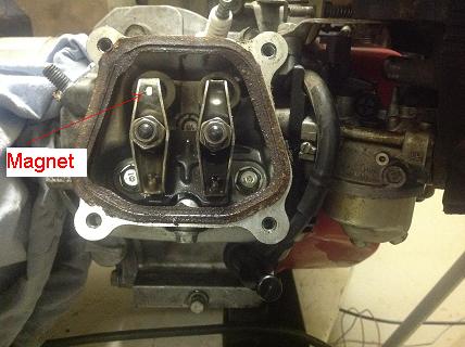
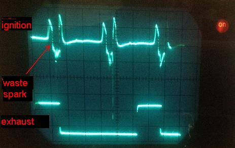
In order to eliminate the waste spark, we first of all need a signal which tells us whether or not the valves are open. One way to get such a signal is to mount a small magnet on the exhaust rocker and use a hall sensor to tell whether or not the exhaust valve is open or closed.
I used a very small magnet, around 5 mm in diameter, and fixed that to the exaust rocker using Magnum Steel Epoxy:
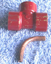
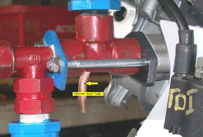
For a hall sensor, I used the TLE 4905 L, which I mounted on the engine using a piece of copper tube:
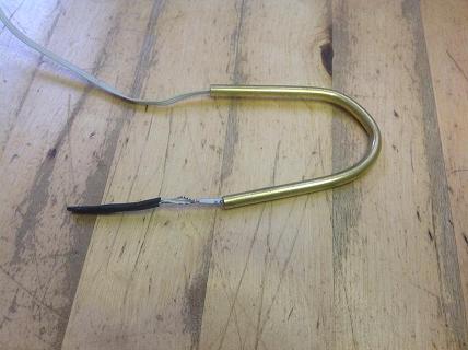
I soldered the tube on the rocker cover:
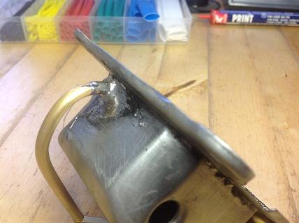
I have adjusted the exact position of the sensor / tube has been a few times, before I got the optimal position, such that the sensor is activated / deactivated when the valve is about half way pressed.
The finished sensor construction:
I tested the sensor using an oscilloscope, wherby I also measured the voltage on the spark plug using a home made probe, essentially a 1:1000 voltage divider, which I would not advise using with a digitial scope:
This way, we can clearly see that this engine does produce a waste spark while the exhaust valve is open:
More images here: http://www.tuks.nl/WFCProject/img/Hall_Sensor/
Making the "cold water fog"
Kelly's guide includes a section "The Step-by-Step Conversion of a Generator", including detailed photographs and explanations how to make water fog using a venturi tube, which is not hard at all to make:
Yet another technique for making the cold water fog
I mailed Patrick the following question:
His answer:
Well, that sure would make life a lot easier. There are carburetors available with adjustable nozzles, such as this one:
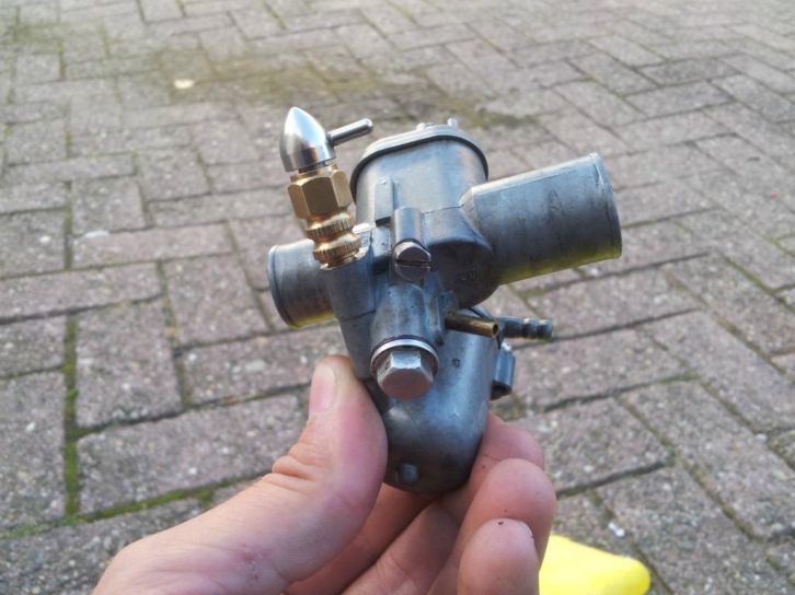
So, with one of these one can not only make the cold water fog with an off-the-shelf component, one can also adjust the amount of cold water fog being injected into the air stream while the engine is running and thus tune the system on the fly.
Needless to say, my first attempt will be with a carburetor with adjustable nozzle. In fact, I placed a bid on the one shown in the picture above already.
Notes
Just some notes which might come in handy.
Dump & edit from: http://open-source-energy.org/forum/showthread.php?tid=1168&pid=15808#pid15808
The idea at that moment was to use aluminum tubes, because with those we know how to grow a suitable dielectric layer. Now that problem is solved by using electropolished stainless things are a bit different, but it gives some considerations.
Essentially, what we plan to do is to do what Dave did, but only exchange the normal Stainless Steel pipes for Electropolished ones. Then, we don't have to grow a dielectric layer ourselves, but it is good to study electrolytic capacitors and understand how these are made and how these work. There is an excellent book about that:
http://www.faradnet.com/deeley/book_toc.htm
For those who are not convinced yet that there is more to a dielectric than meets the eye, I wholeheartedly recommend watching this video:
http://www.youtube.com/watch?v=9ckpQW9sdUg
To quote Eric Dollard on this one:
http://www.tuks.nl/wiki/pmwiki.php/Main/EnergeticFormPosts
All right, the shopping list:
[Note: this part still talks about aluminum pipes]
First, the tubes. Stan used 16" or 40 cm. Lawton used 1" outside diameter for the larger tubes and a gap between the tubes of about 1-2 mm. In the Netherlands, tubes can be bought here:
http://www.ijzershop.nl/280-buizen
It should be noted that there normally already is a dielectric layer on the tubes, which will most likely have to be removed. We still have to figure out how to do that, because the tubes will have to be roughened in order to increase their surface area, but we will probably go for cleaning and etching, since that is the most easy with round pipes.
We plan to go for 25x20 for the outer tubes and 16x12 for the inner tubes, so we get a gap of 2 mm.
We still have to decide about the number of pipes, which will either be 6 or 9. Lawton used 6, but Dr Scott Cramton used 9, which gives the option of running with three phases.
However, as it looks now, I prefer to stay as close to Lawton as possible, because that gives the best comparison with available results and the available kits we plan to use are also designed for that configuration.
So, we would need 6 x 40 cm of both tube sizes.
For the housing of the cell and other components, we are looking at this site, which sells almost all the needed parts and electronics under one roof:
http://www.courtiestown.co.uk/index.php/electrolysers/dave-lawton.html
For the use of 40cm tubes, we need 1 plastic tube of 50 cm length: http://www.courtiestown.co.uk/index.php/electrolysers/dave-lawton/dave-lawton-electrolyser-110-x-500-x-3mm-acrylic-tube.html
And 2 end caps: http://www.courtiestown.co.uk/index.php/electrolysers/dave-lawton/dave-lawton-electrolyser-110mm-end-cap.html
Further, I would consider using plastic bolts instead of rubber slides, so I would also opt for a set of these: http://www.courtiestown.co.uk/index.php/electrolysers/dave-lawton/scott-crampton-plastic-srews-kit.html
See this drawing:
[align=center][img][/img][/align]
For the electronics, there are two options available, as far as I understand:
1) The manual controlled PWM version: http://www.courtiestown.co.uk/index.php/electrolysers/dave-lawton/dave-lawton-pwm-kit.html
2) The PLL auto-tuning kit, which can also be manually controlled, *but* also has an auto-resonance tuning circuit: http://www.courtiestown.co.uk/index.php/electrolysers/dave-lawton/dave-lawton-pll-full-kit.html
Of course, the PLL kit has its advantages, but it is more expensive. For these, one can choose for full kits, just the soldered PCB or a bare PCB.
Besides that, one needs a coil. Perhaps buy a couple, because they are not expensive and the wiring and such may be handy for further experimenting:
And, a "fixing kit" is also worth considering:
The only thing that is missing in the shop are the place holders. There are these:
But these have 9 holes of 19 mm diameter, which could be drilled up, but then you still have 9 holes instead of 6. So, we haven't decided on this part yet.
Update: These are for 150 mm pipes and DO NOT fit in the 110 mm version!!
What is left from the shopping list is at least these items:
1) bubbler and other safety material for mounting on a test-engine and eventually perhaps in a car.
2) Gas production meter.
3) Insulation material around the outer tubes and the inner side of the inner tube. This is optional, but it is advised by Kelly to be used.
This is what a friend of mine ordered some time ago from:
http://www.courtiestown.co.uk/index.php/electrolysers.html?limit=30
1 x Scott Cramton complete electrolyser kit
4 x Dave Lawton Bifilar Kit - a simple kit consisting of a 100 x 10mm ferrite rod and 15mtrs of 21SWG ECW.
1 x Set of 54 x M4 x 8 mm nylon bolts c/w nuts for centralising 9 prs of 18" tubes in a Scott Cramton/ Stan Meyer pattern electrolyser
1 x A pair of 144mm diameter HDPE plates pre-drilled with 9 3/4" holes for use in a Scott Cramton replica electrolyser.
1 x Dave Lawton PLL Full Kit - Allows the buyer to assemble and a fully working and boxed PLL to be assembled.
2 x Dave Lawton Stainless Steel Fixings Kit - sufficient bolts, nuts, washers and wire to build a Dave Lawton pattern electrolyser with 6 pairs of tubes.
Be aware that this supplier is a part-time business and it may take some time to deliver large packages (more than 2 kg) outside the UK. My friend then also ordered the pipes there and that took quite some time.