
Les Banki's project
When I was looking for solutions to get rid of the waste spark for my Electropolished WFC Replication Project, I found these two videos mentioning circuitry developed by Les Banki:
http://www.youtube.com/watch?v=UfGRPJWOGvo
http://www.youtube.com/watch?v=JomHUdpQbvw
It turns out that Les developed a lot of circuits for running engines on hydroxy gas, most of which are posted on the overunity.com forum. I collected all Les' attachments and Les was also kind enough to send me the .PCB files, which are made with Protel PCB for Windows, which can be found on the internet with a little bit of searching.
All Les' project files can be found here. There is also a zip file, which contains all the files, as well as a gallery with all the images, which can also be accessed as individual files.
What follows are the contents of Les' word files, slightly edited and enhanced with links and images.
-- Arend --
Update March 2nd, 2014
I received new files from Les, along with the following e-mail:
-- begin email --
This is a MAJOR update on my WFGP. (Water Fueled Generator Project)
As you may know, I have designed a LARGE number of electronic circuits (as well as mechanical designs) over the years! (spanning over 3 computers!) MANY of those designs relate to "water fuel" which were published on several forums. They were meant to be 'building blocks', either used independently or in certain combinations, for experiments made by those who were/are willing to DO things, instead of just talking!
Note that only a few of those designs are used for the current project.
It took several days to 'clean up' (edit) all electronic circuits and documentations which are being used in this current WFGP.
Some had only minor changes while others had major ones.
Further, there are also additional circuits I designed recently which have NOT been published before. Such as:
1. Control panel circuit diagram, pcb layout and control box description
2. Infrared transmitter & receiver circuits used by the two stage electrolyzer water refilling system
3. Hall switch circuit with a buffer stage which eliminates RF interference pick-up!
Note that ALL the electronics sections for this project are now COMPLETE. (tested and working)
In order to avoid future confusion, I have created 4 Folders which only contain files relating to this current WFGP:
'WFGPdoc' contains all text files (circuit descriptions, etc.) -- is complete
'WFGPsch' has all circuit diagrams -- is complete
'WFGPpcb' has all pcb files in the original PFW format -- is complete
'WFGPphotos' there are some photos of the ECU now but will have many more of the entire set-up, as the work progresses.
All related text files have been edited/updated. The edited versions are all dated 2014 and are the only ones which are to be used for this current project.
So, if anyone intends to duplicate this project (or part of it), should only use files from these 4 Folders!
[...]
Note also that I have designed/made a semi-automatic "groove cutting machine" (similar to a CNC router) which is now operational. (It will be pulled apart later in order to paint it since MDF is sensitive to moisture/water!) Further, I also designed/made an automatic vacuum work holding system for this machine. There are NO clamps, NO bolts, NO holes in the work table! Work piece is fitted & released in seconds!
There will be photos of this machine as well.....
-- end email --
All these files can be found here:
http://www.tuks.nl/WFCProject/LB_WFGP/
Overview & explanation of my complete Engine Control Unit design.
In order to AVOID future misunderstandings, I decided to write this overview/explanation but first, I wish to make some VERY IMPORTANT statements and I ask ALL readers: Please make sure you UNDERSTAND them!
The Engine Control Unit (ECU) design I am presenting to the public, IN ITSELF, is NO GUARANTEE to produce enough Hydroxy to run any engine!
The VOLUME and QUALITY of Hydroxy will depend almost ENTIRELY on what kind of electrolysis system is used. (and perhaps some additional factors not covered here) [some examples: �brute force� low voltage, series cells, high voltage series cells, (with or without �resonance� drive), Hasebe replica, Stan Meyer type �resonance� cells, etc., etc.]
My INTENTION (with the numerous building blocks of the ECU) is to provide anyone who is willing to �get their hands dirty� with the necessary CONTROL ELECTRONICS to achieve their goal.
In essence, what I am saying here is:
IF we are to use the old, rather crude and VERY inefficient (around 26%) Internal Combustion Engine at all, we need to provide it with ignition sparks at the correct times, supply fuel (in this case, HydrOxy) at the correct times and in correct volumes.
Further, the fuel pressure needs to be held steady (pressure regulation) and the power required to create the HydrOxy also needs to be supplied AND controlled (limited).
The need for all this control is INDEPENDENT of the method used for generating the required volume of Hydroxy!
In other words, REGARDLESS of which method of HydrOxy generation is employed, the supply & controls described above are ESSENTIAL. However, you have probably noticed that I offer additional circuits as well, not absolutely necessary but desirable for a smooth working control system and power back up (for example: automatic battery charger circuit).
There is also a convenient control panel where all adjustment are made and pressure, current and voltage levels are SET and DISPLAYED.
There is no denying that this design aims at PRODUCTION! (not just for experiments)
Anyone who is not too familiar with general physics, electrolysis, ICE (Internal Combustion Engine) and electronics technology, could be forgiven for perhaps questioning the need for the number of circuits presented!
It is also likely to give an impression of unnecessary complexity and create confusion.
Note that I choose the name Engine Control Unit (ECU) deliberately as its functions are similar to that of the existing systems used by car manufacturers.
However, all unnecessary functions of the �standard� ECU have been left out!
On the other hand, its functions are expanded to include the power supply AND control to create the FUEL itself, HydrOxy.
All circuit sections are mainly ANALOG, using common, cheap and readily available components. (NO �microprocessors�, NO complex software programming!)
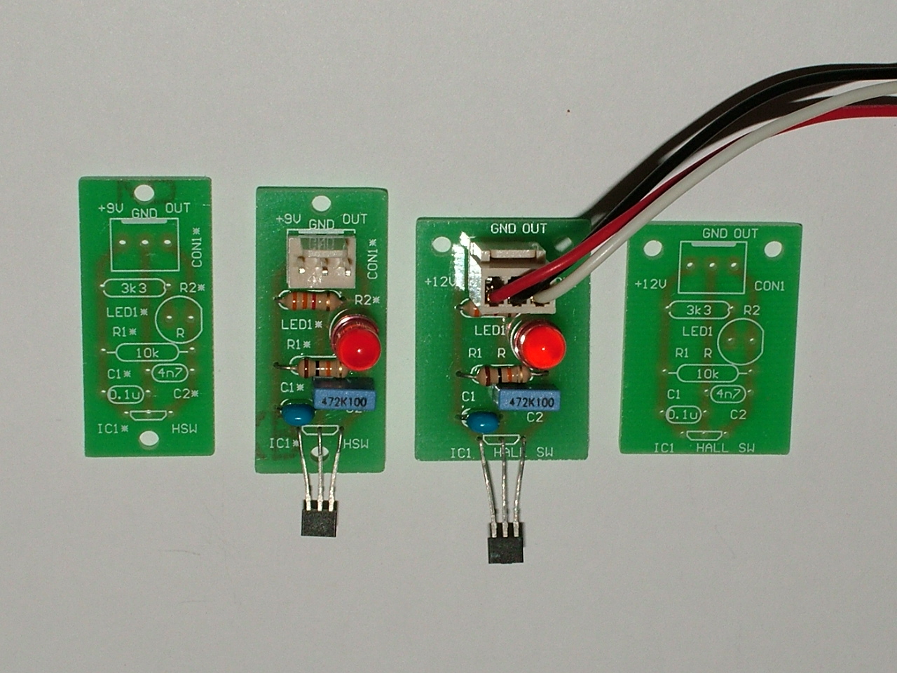
In simple terms, (detailed info in the respective circuit descriptions) here is a list of the circuits I have developed/designed and their intended use:
Hall switch � tiny pcb, mounted on the engine. With a small permanent magnet attached to the exhaust valve�s �rocker arm�, it supplies pulses to the Ignition/Injection control module. These pulses indicate the piston�s position in the engine�s work cycle.
Capacitor Discharge Ignition (CDI) module � when connected to an ignition coil, it creates the required high voltage (20,000V+) to fire the spark plug.
Ignition & Injection control module � supplies the control pulses to the CDI module (WHEN to deliver the sparks) and the drive pulses to the injection solenoid.
Automatic RPM control � automatically brings engine speed from start-up to the correct RPM where the generator supplies approx. 240V with a frequency of 50Hz.
Feed-back control loop � to maintain a STEADY frequency (50Hz) and voltage (240V) output with varying loads.
Auto start � simple circuit which activates the remote control for 3 seconds to start the generator when the set gas pressure is reached.
Pressure regulator module � decides the desired pressure �scale� (PSI, kPA or whatever), Sets and displays the pressure limit and continuously monitors and displays (on the control panel) the actual pressure.
Battery charger � automatic charger, used to maintain FULL charge AT ALL TIMES on a stand-by battery which will be necessary once mains power is no longer connected. (for re-start after maintenance stops)
Power supply (regulator) module � supplies +12V-1, +12V-2, -12V, +5V and -5V to the various modules and sensors.
Water level sensor & pump driver 1 � used to automatically detect the minimum water level in the electrolyzer unit and refill to the set maximum level when necessary.
Water level sensor (& pump driver) 2 � used to detect the minimum (Danger!) water level in the flash-back arrestor and SHUTS DOWN the electrolyzer power supply! Can also be used (with a second pump) for automatic re-fill of the flash-back arrestor.
Relay board � a universal AC/DC 30A relay with a 12V DC coil, transistor driver and indicator LED. Can be configured for either start-up/run or for general HIGH power switching and is used mainly with the timer & timer interphase circuit.
Timer & timer interphase module � while NOT essential, it is VERY �handy�, particularly for REPEATED experiments. It eliminates time measuring errors and a lot of �guess work�. Also eliminates large mechanical power switches! It can also be used to stop the engine/generator after a pre-set time (up to 24 hours!) ''' Test oscillator''' � it is powered up ONLY during set-up (when the engine is not turning there are NO pulses from the Hall switch) it provides the pulses needed for testing.
However, since this oscillator is NOT used during normal operation, if desired, it could be used to flash the LED which indicates power SHUT DOWN to the electrolyzer in the event the flash-back arrestor�s water level drops too LOW.
Control panel � See circuit description for the functions which can be SET and DISPLAYED.
Closing notes:
Once again, as indicated in this overview, not all circuits are being used at the same time. I have tried to cover everything I could think of which I thought would the necessary and/or desirable to control. This would give a choice of options, if you like.
I wanted ALL electronic controls in place and available when (or if) they were needed, just so I would NOT need to run �back to the drawing board� (computer) to do more designs in the middle of the physical work with engines!
Coming up with the concepts, developing/designing the circuits, drawing the circuit diagrams and pcb layouts, writing the circuit descriptions (and other writings), chasing part samples needed for the designs, etc., has taken over 5 years of hard work.
If I have missed or left out something, let me know! I will do my best to fill the gap!
Finally, judging by the number of posts on several Forums, the ignition and �waste spark� issues have received a fair bit of attention lately. Quoted here is part of just one such post to help me illustrate my point:
So what IS my point?
Well, just about every engine BRAND and MODEL is different. Some may be able to be modified like that above, some won�t. And so, here is the BIG question:
Which of the two options (below) do you prefer?
1. The above mechanical method: gears, rods, welding, etc., which (as described) is a power hungry Kettering system, drawing between 5 and 10A! (60 � 120W)
OR,
2. Fit a small magnet to the exhaust valve�s rocker arm, attach the tiny Hall switch pcb to the engine block and then turn a potentiometer on the control panel to set your desired ignition point, continuously variable +/- 45� from TDC, while the engine is running!
Oh, by the way, my CDI system draws only 0.5A. MAXIMUM power draw is 6W!!)
Les Banki
(Electronic Design Engineer)
Water Fuel & LBE Technologies
The Hall Switch
Ignition system for small engines running on Hydroxy ONLY
It should be obvious that with Hydroxy as the ONLY fuel, the use of 2 stroke engines are ruled out since they require oil to be mixed with their fuel for lubrication.
Therefore, only 4 stroke engines will be considered in this brief.
First, some engine data.
The crank shaft on a 4 stroke engine turns twice (720�) for every �work� cycle. Since most (if not all) small engine designs use a magnet on the fly wheel (which is mounted on the crankshaft) to generate the ignition sparks, 2 sparks are delivered for every work cycle. The second spark (which is delivered during the exhaust stroke) is NOT needed and so it is called �waste spark�. With hydrocarbon fuels it is harmless.
However, with Hydroxy ONLY, this �waste spark� MUST be eliminated.With hydrocarbon fuels, ignition usually takes place around 8� before TDC to allow some atomization of the fuel before the actual �explosion�, which occurs approximately 10� after TDC.
If Hydroxy is ignited at ANY point before the piston has reached TDC, the explosion takes place at that INSTANT. (There is NO delay or atomization here since it �burns� about 1000 times faster than hydrocarbon fuels and it could be said that it is not �burning� but exploding!) The force of the explosion instantly tries to push the piston DOWN when it is still trying to come to the top to complete its compression stroke!
That is most undesirable!
When the ignition is delayed (retarded) to the point where the explosion usually occurs with hydrocarbon fuels (around 10� after TDC) then the piston�s downward movement is reinforced and useful work is gained.
Now, consider what would happen if the waste spark was NOT eliminated. As stated above, the crankshaft revolves twice for every �work� cycle. (The first revolution covers the intake and compression stroke and the second one the power and exhaust stroke.) Thus, the second spark (�waste spark�) occurs just before (the same degree of advance as the wanted spark, about 8�) before TDC at the end of the exhaust stroke.
But when the ignition pulse is delayed to be after TDC, the waste spark will occur at the beginning of a new �cycle�, where the intake valve has just started to open.
So now, with a slightly open valve there is an open path to the fuel line (Hydroxy), and there comes a spark! Guess what happens� Guaranteed back fire!
And I can assure you that even the most minute opening will allow the �flame front� to propagate back to the supply line. How do I know? Experience. Lots of it.
Further, let me tell you that I have personally not found ANY method of stopping back fires to propagate back to the electrolyzer, EXCEPT water. While most people call them bubblers, I prefer the name �flash-back arrestor�, since that is their true role. If you doubt the above statements about stopping flash backs traveling back to your electrolyser and DESTROY it, by all means, ignore the advice. Not only will you DESTROY your electrolyser but very likely injure or even KILL yourself and/or others!
An example of engine calculations:
I bought a new, 118cc, one cylinder, 4 stroke petrol engine for Hydroxy experiments. Its rated max. output is 4 horsepower (2960W) at 3600RPM. For the ease of calculations, lets round up the capacity to 120cc (0.12L) This is the maximum volume of air/fuel mixture it can suck in during its intake cycle.
As stated before, the engine�s �work� cycle number is half the crankshaft revolution.
Thus, at 3600RPM, the number of fuel intakes is 1800/minute. 1800 x 0.12L = 216L/minute
However, as only 1% of QUALITY Hydroxy (mixed with 99% of air) is needed to obtain the same power as petrol, this 120cc engine should require only 2.16L/minute of Hydroxy to run at 3600RPM!! (Naturally, it would require less at lower speeds. It remains to be seen if it will require more under full load than this calculated volume.)
Now a few notes about the necessary ignition delay and how to achieve it.
In one article it was suggested that one could use a 555 IC to delay the ignition pulse. Yes, that could be done but it would only be correct at ONE speed.
The reason is obvious:
Ignition advance/delay is related to piston position, NOT time. It is expressed in �degrees� but for hydrocarbon fuels it is varied slightly with engine speed. (due to its relatively slow burning) With Hydroxy, ignition will take place at the same �degree�, (same position of the piston) regardless of engine speed.
At this stage, a couple of things are clear already:
One: on my test engine (and I dare say on most, it not all, small engines) it is not possible (meaning: NOT practical) to eliminate the �waste sparks�.
Two, there is NO provision for ignition timing adjustments, neither mechanical, nor electronic.
In other words, the existing ignition systems used on small engines are USELESS for Hydroxy. We need a NEW electronic ignition system, complete with ADJUSTABLE delay.
So how can that be done?
Again, two revolutions of the crankshaft is 720� (two circles but one �work cycle�).
The camshaft, (controlling the valves) however, turns only ONCE, which is 360�.
In electronic terms, that is 100%.
We want to delay the ignition timing from where it is now, say, from 8� before TDC to 10� after TDC. That is a delay of 18�.
The equation is: 360 : 100 = 18 : X Re-arranging it: 360X = 1800, X = 5
In other words, 18� is 5% of 360�.
We need to delay our original ignition pulse by 5%, irrespective of frequency. (the �frequency� here is the engine�s revolution)
The above example serves to illustrate the difference between the �old� and the �new� settings, assuming that the degree settings relate to the camshaft revolution, 360�.
However, as I understand it, the ignition advance/retard degrees are usually expressed in terms of crankshaft degrees (720� - two revolutions of the crankshaft)
In that case, the above percentage of 5% is halved. Then, 18� is 2.5% of 720�
Since we need a NEW ignition system, this �delay� will no longer relate to the �old� setting. A new signal is taken from a sensor (Hall switch) mounted on the engine, detecting the intake (or exhaust) valve�s position. Using the signal from this sensor, the ignition spark could be made to occur anywhere but we want it approx. 10� (or more) after TDC (adjustable within a few degrees)
Of course, our reference is still TDC.
When we express all that in electronic signal terms, the intake stroke (piston travels from TDC to BDC) is � of the engine�s work cycle, which is 25% of our wave form. (90� of the work cycle and 180� of crankshaft rotation)
If we transform the delays from degrees to percentage, we get the following figures:
10� ATDC is a delay of ~1.39%
25� � ~3.47%
So, if we want the adjustment range of 10� - 25�, the percentage difference is 2.08%.
[We can also calculate the elapsed time this translates to, for any given speed. For example: at 3600RPM, the �frequency� is 30Hz. One period is 1/30 = 0.0333sec. Thus, a 1.39% delay means that the piston has traveled (from TDC) for 463.3�s to reach the position of 10� ATDC (relating to crankshaft revolution)]
One simple way to implement these delays is to use a PWM (Pulse Width Modulator) circuit, which is my preferred choice. (How this is done will be described in detail in a technical �circuit description�.)
It needs to be pointed out that the ignition system for Hydroxy ONLY (not just a booster) will be very different from ignition systems for hydrocarbon fuels.
It will be significantly simpler.
There will be NO �speed mapping�, NO �load mapping�, NO retard/advance change with engine RPM, NO rich/lean mixture setting, NO cold start setting, NO �knock sensor�, NO fuel/air temperature sensor, NO Oxygen sensor, etc., etc., (�modern� engines are full of all that rubbish!)
There will be NO need for high energy sparks, multiple sparks, etc.
Further, there will be NO such thing as UNBURNED fuel remaining in the cylinders!!
In short; when we get to the larger engines (cars), the first thing we have to do is to rip out the �computer� and install our own system, incorporating electronic injection as well. (Perhaps another option could be to completely re-program the �computer�, provided that one could obtain the original programming software from the manufacturer, which, I would say, is HIGHLY unlikely!)
I am in favor of electronic injection (but ONLY for Hydroxy) for two reasons:
1. I reason that if we allow Hydroxy to flow continuously, some of it may disappear during the other � of the engine�s work cycle. (the intake stroke is only � cycle)
2. If Hydroxy is ALWAYS present in the intake manifold, we may risk a damaging back fire.
I am aiming at a mainly analog design, using parts available everywhere and are dirt cheap!
Should a fault occur, it will be quick, easy and cheap to repair.
Les Banki
(Electronic Design Engineer)
Water Fuel & LBE Technologies
Important notes about the Ignition & Injection control circuit and Test Oscillator
While this control circuit is relatively simple, testing and adjustments DO require some test equipment AND a certain degree of knowledge in electronics. Unless you have both, (or know someone who does and is willing to help you) you should NOT attempt to duplicate this circuit.
If you decide to go ahead, you should be aware of the following:
Unlike the CDI module (which creates the ignition sparks), this Ignition/Injection control circuit cannot be tested/adjusted without a dual trace oscilloscope !
Even if you buy a ready made board, it may still need to be re-adjusted (perhaps only slightly) to suit your particular engine type!
The reason is that the position of the pulses delivered by the Hall switch depends on how and where the activating magnet is attached to the engine.
This design is based on Hall switch US2881UA, made by Melexis.
It has very high sensitivity and is Bipolar. That means both polarity (N & S) of the magnet can be used for switching but that too will affect the pulse position slightly. (However, other types of Hall switches can also be used, with or without modifications.)
For the above reasons, the EXACT pulse position in the engine�s working cycle can only be determined by electronic measurements when everything is in place and the engine is turning! (by hand or by starter motor)
If all this appears to be somewhat complicated, well, it is!
But there is more. The pulse input circuit has a relatively high input impedance (determined by R10, 100k). If the Hall sensor end of a long wire is left open (not terminated) it is prone to pick up interference which upsets operation. (For example, should it pick up mains hum (50Hz), it may deliver sparks at mains frequency rate, without the engine turning!) Once the Hall sensor is connected, everything is fine since it has a LOW impedance output. Still, I suggest you keep the connecting cable (3 wires) to the Hall sensor as short as practical. Shielded cable is recommended.
For set-up & testing purposes, the pulses normally coming from the Hall switch must be substituted with some other signal source.
To eliminate the need for a dedicated pulse generator, I am offering a very simple design of a 4046 (PLL) based square wave oscillator. (VCO) (Note: It does not have to be low duty cycle pulse since the input of the control circuit ONLY responds to the RISING EDGE of the waveform.)
I choose to put this simple circuit on a separate (small) circuit board and it is intended to be PERMANENTLY attached to the system but only connected (powered up) during set-up and testing. There is not much to be said about this very basic circuit but perhaps I should mention that its frequency range is restricted to approx. 1Hz - 40Hz.
The restricted range also eliminates the possibility of setting incorrect frequencies.
Les Banki
(Electronic Design Engineer)
Water Fuel & LBE Technologies
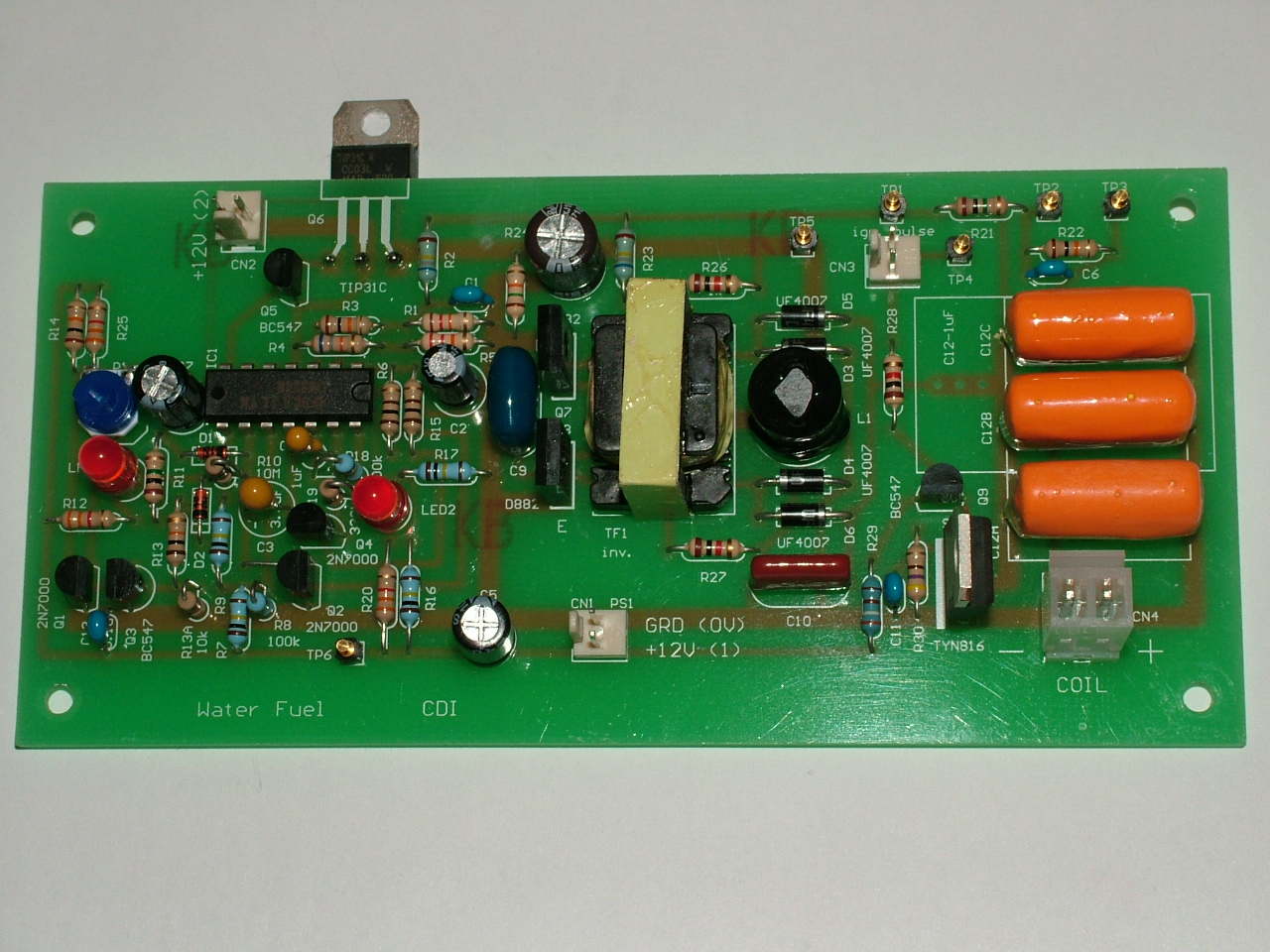
Capacitor Discharge Ignition (CDI) module
Introduction
This brief explanation may assist those who are not familiar with Capacitor Discharge Ignition.
A capacitor (usually about 0.5 � 2uF) is charged to about 300 � 350V. The formula for the stored energy in each charge is: E=1/2�C�V�
In words: the energy (E, in Joules) = capacitance (C, in Farad) multiplied by the voltage (V) across the capacitor, squared, multiplied by 0.5 (or divided by two, same thing)
For example: in the CDI design I am presenting here, the capacitor is 1uF. It is charged to 330V before it is allowed to discharge. The stored energy (E) in each discharge is: 1/2�1�330� = 0.05445 joules or 54.45 mjoules. [Incidentally, the required minimum spark energy for Internal Combustion Engines (ICE) is said to be about 25 mjoules. (millijoule = 1/1000 joule)] As you can see, a 1uF capacitor delivers more than twice that minimum.
Of coarse, lowering the voltage decreases the energy. (AND also the average charging power required!) In case the capacitor is charged to only 300V (which will still deliver at least 20,000V to the spark plug), the energy in each charge is 45mjoules. (Still almost twice the claimed minimum.)
Again, note that the voltage (V) in the formula is squared. This means that even a relatively small change in the voltage (increase or decrease) results in a significant increase or decrease of stored energy. However, keep in mind that HydrOxy requires considerably LESS spark energy.
(Even a very low energy electrostatic discharge spark is sufficient to ignite HydrOxy!)
Capacitor Discharge Ignition differs significantly from the well known (and old!) �Kettering� system. Instead of feeding the primary winding of the ignition coil with LOW voltage (12 � 14V) and HIGH current (5 -10A), HIGH voltage (300 � 350V) and LOW current is dumped into the primary winding from a charged capacitor. Thus, the POWER requirement of the CDI system is only a fraction of the Kettering system! The design I am presenting here uses about 6W while the Kettering type ignition use 50 � 120W, depending on the design. The above mentioned 6W power consumption is for a system requiring a maximum of 50 discharges per second which corresponds to 6000RPM for a ONE cylinder engine.
Naturally, for multi cylinder engines the power consumption will increase somewhat as the number of charge/discharge cycles increase.
The high voltage (300 � 350V) needed for a CDI system is obtained by using a DC � DC converter. There are several types of DC � DC converters but all of them use an inductor or transformer of some sort. Such a transformer (or inductor) usually has to be custom designed. All designers face this problem. Most (if not all) manufacturers are not willing to design/make just a few pieces. Unless one is prepared to order large quantities, they are NOT interested. Thus, the cost of any new design is very much an issue!
There is a very good reason for telling you all this. Everyone who intends to duplicate this circuit needs the following information:
While investigating several options, I discovered that several types of
commercially made
DC � DC converters are available to power CFL�s (Compact Fluorescent
Light).
One of these little beauties are sold here by Oatley Electronics for a
grand sum of \$4.00!!
www.oatleyelectronics.com
(one could hardly get a transformer for that price!)
But there is a catch. Its output is over 500V! (unloaded) That is WAY too high for a CDI unit! Loading alone does NOT bring the voltage down to the desired value AND its output changes with load changes! So, its output needs to be REGULATED. There are basically two ways to do this. One is to regulate the bias to the two driver transistors, the other is to regulate the input voltage to the unit. I have tried both. When regulating the bias, both transistors need to be heath sinked since they are no longer turned on fully and so they run hot. I found regulating the input voltage to be a lot better option.
Since this design is based on this particular CFL inverter (or rather, its transformer), everyone who intends to duplicate this design will face the same practical �problem�. My circuit and pcb layout for this CDI system is built around this transformer. I have actually bought a large number of these inverters. (there is no point designing pcb�s for just a few units). I strip these units, discard the original (round) circuit board and transfer the components to my pcb. I found this to be by FAR the easiest and cheapest way to obtain the desired DC � DC converter! In any case, even if I choose a custom designed transformer, duplicators would still have no choice but obtaining THAT particular transformer.
In case this is not acceptable to some of you, you are on your own and you have to �roll your own� design!
Needless to say, I will sell completed units and perhaps kits, too.
Regulating the output was relatively easy. However, during extensive testing I discovered that in case of certain possible fault conditions (more on this later) the DC � DC converter draws excessive currents which over heaths the inverter transformer and destroys the driver transistors.
Therefore, I have added a fairly complex protection circuit which I developed/designed. It gives full protection!
Detailed circuit description
Let�s start with the CFL inverter described above. While the manufacturer/supplier does not offer any kind of description (they hardly ever do!), it is easy enough to figure out how it works. (it is not important) All I want to say is that it is a clever, simple design which seems to be very efficient and works well. It runs at about 100kHz.
Looking at my circuit diagram (pcb pdf,PCB), the components used from this inverter are: TF1, L1, Q7, Q8, C9, R26 and R27.
The output is full wave rectified by HV ultra-fast diodes (UF4007) D3, D4, D5 and D6. C10 (10n, 630V) is filtering the HV output. This 330V (or 300V) output is connected to one side of capacitor C12 (1uF, 400V). The other side of C12 is connected to the �hot� side of the ignition coil primary. The other side of the coil is grounded. (as usual) In other words, the other side of capacitor C12 is grounded through the ignition coil.
The capacitor�s stored energy is discharged into the coil as follows: SCR1 (TYN816) is connected between the high voltage output and ground. Its Gate is triggered by transistor Q9 (BC547), wired as an emitter follower. When ignition pulses (from the ignition module) are fed to its base (through R28, 1k), it turns on and its emitter supplies the trigger current from the 12V supply rail, through collector resistor R29 (390 ohms). When Q9 is turned on, some current also flows through R30 (470 ohms) in addition to the SCR� gate trigger current. The low value of R30 and C11 (0.1uF) shunt spurious transients which could cause false triggering.
When SCR1 is triggered, it becomes (for all practical purposes) a short circuit. Through this �short circuit� the capacitors energy is discharged to ground.
The discharge current also flows through the ignition coil�s primary which is transformed (1:100) and creates a secondary voltage well in excess of 20.000V! (depending on the type of coil used).
Regulating the inverter�s output voltage
As I have stated above, I choose to regulate the inverter�s input voltage.
It is a standard �series pass�, OP amp based regulator. (IC1B, LM324) It drives Q5 (BC547) and Q6 (TIP31B) in a Darlington configuration. The HV (300 � 330V) output is attenuated by R23 (680k) and R24 (15k) and connected to pin 6, IC1B�s inverting (-) input. It is also connected to the emitter of Q6, which is the output of the regulator. The non-inverting input is connected to the slider of P1 (10k), which, with R25 (3k3) forms a voltage divider to restrict the adjustment range of P1. This, in turn, limits the high voltage at the output of the inverter. Since OP amp IC1B is a �virtual earth� amplifier, its inverting (-) and non- inverting (+) inputs are practically at the same voltage. Therefore, the voltage appearing at pin 6 (regulator�s output) will be the same as the voltage on pin 5, the slider of P1.
The voltage divider R21 (990k) and R22 (10k)/C6 (10n) provide a convenient low voltage, low impedance test point TP2 for adjustment/test purposes of the HV output.
Protection circuits
First, I will try to explain why the somewhat complex protection circuit is necessary.
Please look at the circuit diagram. You will see that C12 (the 1uF capacitor which supplies the spark energy) is connected between the HV output and, through the ignition coil�s primary winding, to ground.
Now, consider what happens if C12 goes short circuit. (In other words, there is a short placed on the DC � DC converter�s output!) The poor thing will try to supply power into a short circuit! (with plenty of current but almost NO voltage!) As a result, current draw from the power supply will increase dramatically. This causes the driver transistors AND the transformer to over heath, until something gives!
Consider now an open circuited C12. There is NO stored energy to discharge. Then there is NO charge time to consider. Remember that SCR1 (TYN816) is also directly across the HV output.
Normally, when SCR1 fires to discharge the energy in C12, the current flowing through SCR1 is eventually reduced below its �holding current� so it �drops out�. (stops conducting) When there is NO capacitor, (same as an open circuit capacitor) there is NO periodic discharge, the DC � DC converter is continuously supplying current so SCR1 will NOT drop out. This means an INDEFINITE �short circuit� (in form of a continuously conducting SCR) across the HV output.
Further, the EXACT same condition will also occur if the wire to the ignition coil�s primary is broken or disconnected. (or if the coil goes open circuit)
IC1A is used to detect the presence/absence of the HV. R1 (12k) and R2 (680k) form a voltage divider between the HV output and ground. The voltage developed across R1 is a fraction of the HV and it is fed to the non-inverting (+) input pin 3 of IC1A, used here as a comparator. A fixed voltage (approx. 2.9V) is applied to the inverting (-) input (pin 2) from the voltage divider R4 (68k) and R5 (22k) which is filtered by C2 (10uF). Under normal operating conditions the output of this comparator is HIGH.
Should the voltage on the non-inverting input (pin 3), which represents the HV output, decrease significantly (below the voltage on pin 2, the inverting input) or disappear completely due to a fault condition, the output of the comparator IC1A (pin 1) will go LOW. This output is connected to the Gates of DMOS transistors Q2 and Q4 (2N7000), through R6 and R15, respectively (both 100 ohms). (Note: for this application bipolar transistors are un-satisfactory. Their off-state collector-emitter leakage is too high.)
IC1C and IC1D are wired as square wave oscillators. Since the normally conducting Q2 and Q4 are connected between the inverting (-) inputs and ground, both oscillators are DISABLED. (C3 � 3.3uF and C4 � 1uF are the timing capacitors) In the (sampling) oscillator IC1C, the charge/discharge times are separated. This gives (with the component values shown) approx. 2 seconds HIGH and about 25 seconds LOW signal at IC1C�s output (pin 8). Through D2 (4148) and R13 (10k) this signal is fed to the base of Q3 (BC547) which is used as an inverter. Q1 (2N7000) is connected between ground and the non-inverting (+) input (pin 5) of voltage regulator IC1B. Its Gate is connected to the collector of Q3. When Q3 is conducting, Q1 is NOT. (NO Gate voltage � it is shorted by Q3) When Q3 is NOT conducting, Q1 gets its Gate drive from Q3�s collector through R14 (10k). Q1 is now conducting, bringing the voltage on the non-inverting input (pin 5) of the regulator (IC1B) to 0V. As a result, the regulator�s output is also zero.
NO INPUT VOLTAGE to the inverter means NO current draw. In other words, this is NOT a current limiter. The inverter is completely OFF, drawing NO current.
As long as the fault condition exists, oscillator IC1C continues its 2/25 seconds ON/OFF routine. Its output is inverted by Q3 which then turns Q1 OFF/ON. So, when Q1 is OFF, the regulator (and the inverter) is working normally. When Q1 is ON (conducting), the regulator (and thus the inverter) is cut off. In this condition, there is NO current draw.
In layman�s terms, this is what happens: Due to a fault condition, (capacitor C12 open or short circuit, ignition coil primary open circuit, wire to the coil broken or disconnected�) oscillator IC1C is ENABLED and is producing a 2 seconds ON and 25 seconds OFF signal. This signal ENABLES/DISABLES the regulator supplying the inverter. The 2 seconds ENABLE signal is for SAMPLING. Is the fault still there? Yes. OK, cut power OFF for the next 25 seconds. Then, SAMPLE again (for 2 seconds) to check if the fault has been cleared or not. If not, this oscillator will continue its 2/25 second routine INDEFINITELY.
Since power is applied for only 2 seconds (SAMPLING) and there is NO power for 25 seconds, no harm is done! If the fault has been cleared, the oscillator is disabled and the regulator/inverter once again works normally.
Since indicator LED1 for the sampling oscillator is only turned ON for 2 seconds (and OFF for 25 seconds) there is a need for continuous indication of a fault condition.
That is the role of oscillator IC1D. Under normal working conditions it is disabled by Q4 (2N7000) which is shorting its timing capacitor C4 (1uF). It is wired as a square wave oscillator which, under fault conditions, flashes LED2 ON/OFF about 3 times per second (~3Hz).
Under normal operating conditions, the inverter�s regulated supply voltage output is around 6.4V. Current draw is about 0.5A. With a short circuit placed on the output, the current rises to around 1 - 1.2A. Should the regulator transistor Q6 go open circuit, the inverter simply stops operating. However, should it decide to go short circuit, (unlikely, due to the moderate current draw of only 0.5A) the full rail voltage of 12V would be applied to the inverter and its output would rise to over 500V! This, in itself, should not be a problem, except for two things: 1. Capacitor C12 (rated at 400V) might go short circuit (which would activate the protection circuit described above). 2. The ignition coil would produce excessive secondary voltage which could cause internal insulation break down.
Testing and adjustment
A number of TP�s (test points) are provided for testing and adjustment(s) purposes.
There is only ONE adjustment to be made on this pcb, to set the inverter�s output voltage to the desired value (usually somewhere between 300 � 330V depending on the ignition coil used). Connect a voltmeter (set to 600V or 1000V range, depending on the meter) between TP3 (ground) and TP1 (HV) and disable discharge triggering TP4 by shorting it to TP3. Now adjust P1 to the desired voltage (300 � 330V) You could also use TP2 (and TP3) to adjust to 3 � 3.3V (100:1 attenuator, provided mainly for oscilloscope connection to eliminate the risk of damaging its input)
The regulator�s output voltage (supplying the inverter) can be measured at TP5. For a 330V output it should be around 6.4V.
The operating temperature of the inverter transformer and its driver transistors are a very comfortable 47�C and 45�C, respectively, measured in ambient temperature of 30�C!
Les Banki
(Electronic Design Engineer)
Water Fuel & LBE Technologies
Ignition & Injection control module
Important notice:
The control electronics described below is NOT suitable for engines with manual (pull cord) starters, UNLESS the pull cord is EXTENDED to provide MORE revolutions!
Reason: Recent physical tests of several manual start generators reveal that their pull cord starters only produce two (2) or 3 revolutions of their crankshaft.
That is only ONE (or 1.5) engine work cycle. In order to establish & stabilize the necessary waveform for proper operation, AT LEAST ONE (or more) cycle is required. During this process NO injection or ignition pulse(s) are allowed.
In other words: At least ONE engine cycle (2 crankshaft revolutions) is needed just to establish the correct waveform, WITHOUT injection or ignition pulses! Then, additional revolution(s) are necessary for starting.
Electric starters can deliver as many revolutions as needed and thus solve the �problem�. Needless to say, this involves a battery which will be needed anyway as a start-up supply for the electronics and generation of Hydroxy.
Background
In my thesis, �Ignition system for small engines�, I briefly outlined why a new ignition system is needed with Hydroxy as the ONLY fuel and what are the technical requirements for such an ignition system.
To start with, here are a couple of quotes from an EXCELLENT web site which briefly explains (with moving animation!) ignition technology:
(http://www.gill.co.uk/products/digital_ignition/Introduction/6_4stroke.asp)
Most (if not all) existing small engines use a magnet mounted on the fly wheel which gives two pulses for every engine cycle. (thus generating �waste� sparks)
Electronically dividing by two would NOT solve the problem since another signal would be needed to determine which one of the two pulses we want and which one we don�t.
Only ONE sensor is needed IF it gives only ONE pulse for every ENGINE cycle. It does not matter WHERE in the engine�s cycle this pulse originates because it can be electronically �moved� anywhere in the engine�s 360� (100%) cycle. The obvious choice of a sensor is a �Hall effect� switch.
Since modern engine blocks are non-ferrous (aluminium) alloys, the Hall switch can be placed on the outside of the engine block. For example, it can detect the position of a magnet which is fitted to the valve�s �rocker� arm.
As the �rocker� arm/magnet moves in and out of certain positions, the Hall switch turns on/off.
This sensor must detect the position of the cam shaft (which makes one revolution per engine cycle), NOT the crank shaft (which rotates twice for every work cycle). Looking at most small engine designs, it seems that accessing the cam shaft is easiest at the exhaust/intake valves under the valve cover.
Thus, the mechanical modification consist of fitting a small magnet to the rocker arm of the exhaust (or intake) valve but because the magnetic field is blocked by ferrous metal, if the valve cover is made of steel, it must be either replaced with a non-magnetic one (like aluminium), or, cut a hole in it which is then covered by some non-magnetic material.
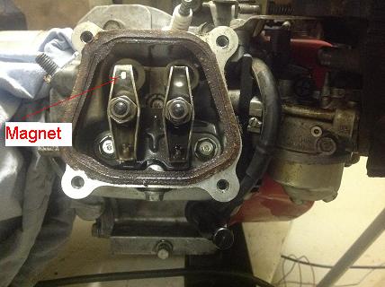
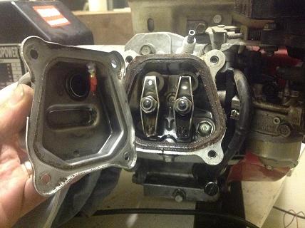
[Note, lamare : here are some images of my hall sensor construction]
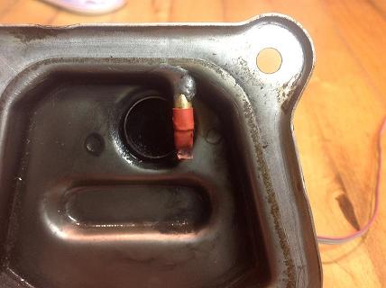
I used a very small magnet, around 5 mm in diameter, and fixed that to the exaust rocker:
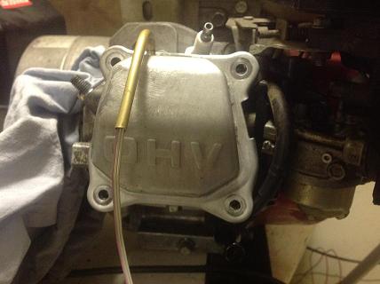
For a hall sensor, I used the TLE 4905 L, which I mounted on the engine using a piece of copper tube:
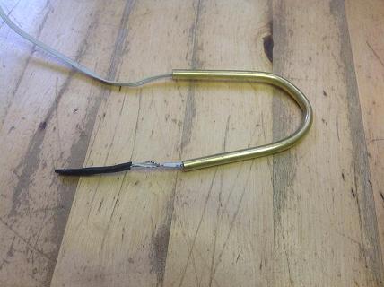
I soldered the tube on the rocker cover:
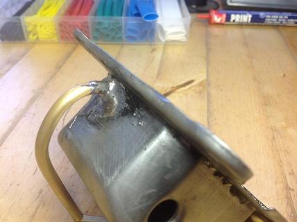
I have adjusted the exact position of the sensor / tube has been a few times, before I got the optimal position, such that the sensor is activated / deactivated when the valve is about half way pressed.
The finished sensor construction:
[end note]
Surely, the above modification should be easier than making a 2:1 gearing!
My choice is to place the magnet on the EXHAUST valve�s (rocker) arm for the following reason:
The EXHAUST stroke is the LAST of the engine�s working cycle. From this point, everything is in the correct order. First the INTAKE stroke, during which the gas will be injected at the correct time (and duration, determining the speed) Now the pulses from the Hall switch can be correctly delayed by the required amounts for the Injection and Ignition functions. Following the INTAKE stroke is COMPRESSION, at the end of which IGNITION takes place.
As the pulses from this single Hall switch usually do not occur exactly where we want them, they need to be �moved� (delayed) to deliver the desired injection/ignition functions at the correct times.
First, some engine basics:
Engine speed is expressed as RPM (Revolutions Per Minute). In electronics, however, the unit of time is SECOND. Since there is 60 seconds in a minute, (it was the last time I checked! (() the engine�s RPM is divided by 60 to get the engine�s �frequency�, in Hz.
Example; an engine running at 3600RPM (crankshaft speed), divided by two is 1800 engine cycles per minute. Divide that by 60 gives 30Hz. It means that the spark plug is going to fire 30 times per second.
One thing is CERTAIN.
IF the fuel is Hydroxy ONLY and when there is a sufficient volume of it mixed with air in the cylinder and a spark occurs, it WILL explode, regardless of correct or incorrect timing!!!
Due to this fact, irrespective of all other design changes, when starting the engine, injection/ignition pulses MUST be inhibited for at least ONE cycle in order to establish and stabilize the saw tooth waveform.
In practical terms this means that the engine would start on the 2nd (or 3rd ) revolution of cam shaft (4th or 6th revolution of crank shaft) which would NOT be within the firs pull of the cord!! (for manual start) For this reason electric start is needed. (or pull cord extended!)
Once again: Since 1 Hz is 2 crank shaft revolutions, the RPM is 120. 2 Hz is 4 revolutions and thus 240 RPM.
Principle of operation:
1. The first task is to convert the pulse train from the Hall switch to �frequency�. [(so that ONE �period� is ONE engine cycle. (4 stroke)] This can be done by either digital or analog means. (or a combination of the two) Both have advantages and disadvantages. While the modern �buzz� word is �microprocessor�, there is no need for it here with its complex software programming. Basically, the two main issues with any design are: simplicity and cost. My choice for this design is analog. It is a relatively simple and low cost design.
2. The engine�s frequency is transformed into a LINEAR saw tooth waveform. This saw tooth is fed to a comparator. The output is a variable duty cycle square wave. [This is the basic principle of the analog Pulse Width Modulator (PWM)]
3. The rising or falling edge of this variable duty cycle square wave is used to trigger the desired ignition/injection action.
New ignition & injection control design
Close examination of my previous design revealed two problems:
1. When starting the engine, an ignition pulse was allowed to occur following the very first pulse from the Hall switch! [At least two (2) pulses are necessary to create & stabilize the desired waveform!]
2. Frequency-to-Voltage converters are inherently slow. When rapidly changing the frequency, large amplitude variations are unavoidable. This plays havoc with the injection & ignition timing to the point of being useless!
Note: all this occurs ONLY at very low STARTING frequencies. (1Hz � 5Hz)
First of all, I have drawn a chart I named �4 stroke engine timing cycle�:
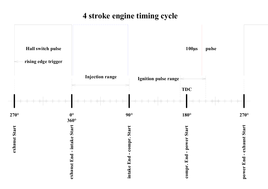
Not only does it aid the understanding of a 4 stroke engine�s work cycle and the injection & ignition process but it also serves as an essential reference for the initial set up of the injection & ignition timing circuits for the engine used.
Like the previous design, this new design is also based on a Hall switch, activated by a magnet attached to the exhaust (or intake) valve�s rocker arm.(Thus, the pulses always occur at the same �degree� of the engine�s work cycle.)
The control circuit�s basic principle of operation also remains the same: creating a linear saw tooth waveform from the pulses supplied by the Hall switch.
However, the new design DOES NOT USE a Frequency to Voltage converter (F/V) which has an inherently slow response. Further, the method of generating the linear saw tooth voltage has also changed. Instead of fast charging the timing capacitor and slowly discharging it with a constant current source, (producing a falling slope) it is now continuously charged by a simple constant current source, producing a rising slope.
The main reason for this change was/is to obtain a Ground (0V) referenced waveform which is much easier to manipulate. (for example in a feed back loop)
The new circuit (pcb.pdf, PCB) operates as follows:
The pulse train from the Hall switch, IC1* (on its own pcb), is fed to monostable IC1A�s rising edge input A (pin 4, 4538 dual monostable) The output pulse width is set to 100�s by R3 (10k) and C3 (10n). These pulses (from pin 6) are fed to the falling edge B input of IC1B (pin 11), the �clock� input (pin 14) of IC6 (4017) and also to the �logic� input (pin 8) of track & hold IC5 (LF398) through attenuator resistors R20 (3k3) and R21 (1k).
Monostable IC1B� (4538-2) output pulse width (100�s, at pin 10) is set by R4 (10k) and C4 (10n). These pulses operate switch Q2 (2N7000) which discharges timing capacitor C5 (0.1�). Continuously charging C5 is a simple constant current source, comprising of Q1 (BC327), D1 (4148), R6 (3k3) and R7 (270k). (Charging time constant is determined by C5 and R7.)
The resulting linear saw tooth is buffered by IC2 (TL071), wired as a unity gain voltage follower. The buffered saw tooth (output of IC2) is fed to both inputs of IC3 (TL071), a Voltage Controlled Amplifier (VCA) through R8 and R9 (both 10k). The �gain� control elements are P-channel JFETs Q3 and Q4 (both J174), operating in their �ohmic� (linear) region, their D-S voltage being restricted to a few tens of milli volts by the inputs of the OP amp. (IC3)
Since the VCA (IC3) is inverting, the next stage, IC4A (TL072-1) is another inverting amplifier with unity gain (-1). Its output signal (from pin 1) is now of correct polarity and is fed to comparator/error amplifier IC4B� (TL072-2) inverting (-) input (pin 6). Its non-inverting (+) input (pin 5) is fed with an adjustable voltage from the voltage divider R16 (8k2), P1 (10k) and R17 (22k). These component values give a range of approx. 6.56 � 9.55V (for 12V supply) and 2.73 � 3.98V (for 5V supply) for setting the saw tooth amplitude to the desired level.
The error signal (from the output of IC4B, pin 7) is fed, through R19 (10K) to the input (pin 3) of track/hold IC5 (LF398). At the peak value of the saw tooth, IC5 is put in the Hold mode for the duration of the following cycle. This DC voltage is fed from its output (pin 5) to the gate of Q3 (J174) JFET.
It is this voltage which sets the gain of the VCA.
Thus, the VCA (IC3), the unity gain inverter (IC4A), the comparator/error amplifier (IC4B) and the track/hold stage (IC5) form a feed-back loop to correct the amplitude of the waveform as the frequency changes. [Suppose the starting frequency is 1Hz and the saw tooth P-P amplitude is set to 8V. (3.33V for 5V supply) When the frequency has increased to 2Hz, the amplitude has DECREASED to 4V (1.66V for 5V supply) and needs to be amplified (x2) to bring it to 8V. (3.33V for 5V supply) At 4Hz, the amplitude is 2V (0.83V for 5V supply) and it is amplified by 4 to bring it to 8V (3.33V for 5V supply) and so on�.)
Unlike the inherently slow Frequency to Voltage converter, this method stabilizes the waveform amplitude after only ONE completed cycle. This is due to the fact that amplifier action is FAST! (device propagation delays are measured in micro or nano seconds!)
The amplitude AND polarity corrected saw tooth waveform from IC4A� output (pin 1 & TP9) is fed, through R36 (10k), to the inverting (-) input (pin 2) of another comparator, IC9A (LM393-1). A voltage divider is formed by R34 (22k), P4 (10K) and R35 (33k) and the non-inverting (+) input (pin 3) of IC9A is connected to the wiper of P4 (10k), thus:
P4 is the IGNITION PULSE POSITION adjustment.
The above component values of the voltage divider allow a wide range of adjustment. However, to suit different engine designs, the values of R34 & R35 may be altered.
Since we now have a rising ramp, the voltage on the inverting (-) input (pin 2) of the comparator IC9A (LM393-1) remains below the set point on the inverting (+) input (pin 3). As a result, the output of IC9A stays HIGH until the set point is reached. When that happens, the output snaps LOW. This falling edge pulse triggers monostable IC8A (pin 5). The output pulse width is set to 100�s by R38 (10k) and C17 (10n) and is available from pin 6 (Q output of IC8A).
These 100�s pulses are fed to the base of �emitter follower� ignition trigger transistor Q9 (BC 547) through R39 (2k2) and R28 (1k). Q9� collector resistor R29 (390 ohms) supplies the necessary trigger current for SCR1 (TYN816). R30 (470 ohms) & C11 (0.1�F) help to reduce/eliminate spurious noise pulses from the SCR�s gate. (Note: Q9, R28, R29, R30, C11, SCR1 and capacitors C12A,B,C are on the CDI module)
Capacitors C12A,B,C (1�F 400V) are continuously charged to 330V by a DC-DC converter. The stored energy is then dumped into the primary winding of the ignition coil. Thus, it is a CDI (Capacitor Discharge Ignition) system.
In practice, ALL generators are run at a CONSTANT speed somewhere in the range of 2000 to 4000RPM (depending on design). (Remember, this ignition system is designed specifically for ONE cylinder generators.)
Injection
In the general practice of the �art�, the injection solenoid is sometimes turned on just before the intake valve opens to gain a little extra time for injection. (But it must be turned off before the valve closes.) The volume of gas injected is determined by gas pressure AND the solenoid�s ON-time.
Just as with the ignition, injection timing is related to the engine�s work cycle.
The injection circuit is almost identical to the ignition circuit with a couple of differences. Just like the ignition circuit, the injection comparator (IC9B-LM393-2) gets its linear saw tooth signal from the output of IC4A (pin 1 & TP9), connected through R30 (10k), to its inverting (-) input (pin 6). The non-inverting (+) input (pin 5) is connected to the wiper of P2 (10K) which is part of a voltage divider. [R28, (68k) � P2 (10k) � R29 (15k)]
P2 is the injection STARTING POINT adjustment.
Again, because of the rising ramp, the output voltage from IC9B (pin 7) is HIGH until it reaches the set point. Then it snaps LOW and this falling pulse triggers monostable IC8B (pin 11). Its output pulse length is determined by P3 (100k), R32 (15k) and C15 (68n). With these component values it is adjustable from about 1ms � 8.2ms.
P3 is thus the SPEED (RPM) control of the engine.
Note: If using the automatic RPM control module, monostable IC8B is now used to create short, fixed time constant trigger pulses to the VCT on the auto RPM board. Now R32 is 22k, C15 is 1n and P3 is replaced with a shorting link. (time constant approx. 22us) The negative going pulses are taken from the Q-bar output (pin 9) and fed to control pin 5 of the VCT. All solenoid driver components are omitted and are fitted to the auto RPM board instead.
The MTP3055E MOSFET has an in-built protection diode. (If MOSFETs without in-built diodes are used, an external diode MUST be fitted!)
In addition, in order to eliminate the very large (close to 100V!) BEMF pulses generated by the solenoid coil, diode D3 (4007) must be fitted across the coil.
ANY power MOSFET can be used which can comfortably switch 2A or so. (It is most unlikely that you need to use a higher current solenoid.)
I have tested 2 gas injector types: one draws just under 1A and the other just under 2A. Since the ON resistance of most power MOSFETs are in the �milli ohm� range, there is no need to put the MOSFET on a heath sink. Further, the injector solenoid is only ON for � of the total time (during INTAKE) and thus its �duty cycle� in only 25%. (max.)
Blocking injection/ignition pulses at start up:
An ACCURATE method is a digital pulse counter feeding a retriggerable monostable, which in turn enables/disables the monostables delivering the injection/ignition pulses.
The pulses from the Hall switch (or from the monostable) are clocking decade counter/decoder IC6 (4017), which counts the pulses. At the desired number, say, 3 pulses, the counter is reset and at the same time it delivers pulse number 3 to IC7B (4538-2), configured as a retriggerable monostable.
The time constant of this monostable output pulse must be at least 3 pulse periods from the Hall switch, in order to prevent it from terminating its timing cycle. This means that at the very low cranking speed of the engine, say 1Hz (120RPM), it needs to be just over 3 seconds.
In practice, the time constant can be set to 4.7 seconds (approx.), using a 1�F capacitor (C13) and a 4.7M resistor (R26). (T = R*C, 4.7*1 = 4.7s)
This is the way it works:
When power is applied, all stages are RESET. (Hall switch, counter, monostables, etc.) In particular, the retriggerable monostable IC7B�s Q output (pin 10) is LOW when reset. It disables injection pulse monostable IC8B by pulling its CD (clear) input (pin 13) LOW by forward biasing D3. (diode �clamp�) Likewise, ignition pulse monostable IC8A is also disabled by pulling its CD (clear) input (pin 3) LOW. Thus, since IC8A & B are disabled, NO injection or ignition pulses could occur, even if trigger pulses are supplied.
Details:
By cranking the engine, the Hall switch starts delivering pulses. The counter, IC6 (4017), counts these pulses. When the pre-set number is reached (say 3), it resets itself and at the same time it triggers the retriggerable monostable IC7B, with a set timing period of 4.7 seconds. In the reset stage, its Q output (pin 10) is LOW.
For normal operation, R27 (10k) keeps the CD inputs of the injection & ignition monostables IC8A & B HIGH. During the pulse count after a reset, the CD inputs of IC8A & B (pins 3 & 13) are held low by IC7B� LOW output and the clamp action of D2, disabling them. When the set count is reached, IC7B� output goes HIGH and that enables operation of IC8A & B by removing the clamp.
Repeat: from reset, during the pulse count, IC8A & B are disabled. When the set count is reached, IC8A & B are enabled to operate normally, allowing injection & ignition pulses to be delivered to their respective circuits.
As the engine picks up speed, the pulse period from the Hall switch gets shorter. However, due to the long time constant of 4.7 seconds, even if the engine speed remained at a very low RPM indefinitely, the monostable timing period could still not terminate, so ignition pulses would be delivered as normal. During normal operation, monostable IC7B receives only every third (3rd ) (or higher) pulse as trigger pulse from the counter. (This stage can be considered as a �missing pulse� detector.)
When the engine has stopped, it takes 4.7 seconds (after the last trigger pulse) to terminate the monostable�s timing cycle and once again clamp the ignition pulse delivery. In practical terms it means that the engine can be re-started after about 5 seconds with a guaranteed blocking of the first 2 (or 3, as required) ignition & injection pulses!
Note: 3 pulses from the Hall switch constitute 2 full engine working cycles. (Between 1 and 2 is ONE and between 2 and 3 is TWO full engine work cycles.) Keep in mind that the third (3) pulse is the start of the THIRD cycle and subsequent ignition pulse.
Testing and adjustments:
First, a variable frequency (1Hz to 40Hz) pulse generator is connected to TP4. (Hall switch input) To test & adjust this circuit, a DUAL TRACE oscilloscope is essential. When using BOTH probes, I suggest you connect only ONE of the ground probes as the circuit is sensitive to �ground loops�. (they may upset not only the measurements but also the operation of the circuit itself)
Set up adjustments of this new design are considerably simpler than the previous one!
Apart from the CONTROL PANEL adjustments of the IGNITION point (P4) and SPEED (P3), there are only two other (pre-set) adjustments: 1. Saw tooth amplitude, using P1 (set DC voltage at the wiper of P1 to 8V) 2. Injection STARTING point with P2
This Ignition/Injection control circuit, together with the CDI module and the Hall switch, forms a COMPLETE ignition system.
Before you decide to go ahead building/using it, you should also read �Important notes about the Ignition & Injection control circuit and Test Oscillator�.
Notes: VCA (IC3) MUST be a single OP amp package. For some strange reasons [which I had no time (or desire!) to investigate], it refuses to work properly with an OP amp from a dual or quad package!
The saw tooth amplitude DOES vary somewhat. It is highest at the low frequency end (1Hz), decreasing to a steady value in the desired frequency range 15 - 30Hz (1800 � 3600RPM) where most engines will be running. However, this small amplitude change can be ignored since the engine spends very little time in the cranking mode (very low RPM) and the ignition point there is not critical.
What IS important is that it is STABLE in the required running RPM range.
Les Banki
(Electronic Design Engineer)
Water Fuel & LBE Technologies
AC power cotrol circuit description.doc
AC power control circuit description
This circuit was developed/designed for powering high voltage, multi cell electrolyzers. (However, it can also be used as a high power light dimmer, motor speed controller, etc.)
It employs AC phase control, using a Triac. (which is a very robust and reliable device!) Phase control necessitates the use of a random phase optoisolator Triac driver (like the MOC3021) and the design of a synchronized zero crossing detector and a current limiter. Using the components indicated on the circuit diagram, it will run comfortably at 240VAC at 10A � which is 2400W! It can be scaled up by using some components with higher ratings.
Through a bridge rectifier, the phase controlled mains AC power is applied DIRECTLY to the electrolyzer! (NO transformer!)
Some may not like the idea but the advantages of a transformerless circuit for this purpose FAR outweighs the disadvantage of a LIVE electrolyzer. (I am talking about a 120 cell, 240V unit.) LIVE or NOT, you keep your hands OFF a 240V device, AC or DC! Period!
The only technical �problem� I have encountered is the necessary isolation of the current limiter control signal from the �live� mains. (More about this later.)
Zero crossing detector:
From the mains transformer�s secondary (15V), diodes D1 and D2 (4007) feed pulses to the inverting (-) input (pin 6) of the zero crossing comparator IC1B (LM324) through a voltage divider R1 (1k) and R2 (1k), clamped to +12V by Zener diode ZD1. [This is done to avoid the pulse amplitude exceeding the power supply (12V)].
The non-inverting (+) input (pin 5) is biased by R3 (100k) and R4 (470ohm) to about 56mV (0.056V). Narrow, positive pulses appear at IC1B�s output (pin7). These are fed through R5 (10k) to discharge switch transistor Q1�s (BC547) base. A constant current source [comprising of Q2 (BC 327), LED1 and R7 (3k3)] is continuously charging capacitor C1 (0.1u). Q1 periodically discharges C1, thus a LINEAR saw tooth waveform is formed. (the fast discharge part of the waveform occurs during zero crossing of the sine wave)
IC1C is a unity gain �voltage follower� (low output impedance buffer). Its output (pin 8) is connected to the non-inverting (+) input (pin 12) of the PWM comparator (IC1D). The inverting (-) input (pin 13) is biased by R8 (1M2) and R9 (10k) to around 12mV (0.012V). This corresponds to the maximum output power for this type of circuit. (which is about 95%) In other words, this is the output control pin. The control voltage is applied to this point through diode D4 (4148).
In this configuration, (as required for the purpose of current limiting) when the voltage increases, output power decreases.
The output of the PWM comparator IC1D (pin 14), through R10 (10k) and R11 (1k), drives the Gate of Q3 (2N7000). D3�s Anode is connected to the junction of R10 & R11.
Power OFF/ON control is achieved by applying a LOW signal to the Cathode. This removes the drive signal from Q3�s Gate. (This is used for timer operation as well as pressure control.)
The LED in the optocoupler MOC3021 (IC2) is connected between the positive supply rail and the Drain of Q3, with resistor R12 (470R) limiting the current.
The remaining components around the optocoupler and the Triac are for limiting dv/dt, suppression of transients and to reduce RF interference. (C3, C4, C5, R13, R14, R15, VDR1 and L1)
Now to the current limiting:
There are a number of options. Some are �sophisticated� (read: expensive), others are not. Since high accuracy or high speed is hardly required for this application, I have adapted an unusual approach to current limiting.
Using the principle that current flowing in a conductor is heating it, I have a �dedicated�, short pcb track in the current path to the load (electrolyzer, etc.). Over this track I place a diode (like the 4148 which has a thin glass envelope) with heath conducting compound (same as used on heath sinks) for good thermal conduction. It is well known (or should be!) that a semiconductor junction forward voltage drop exhibits a temperature coefficient of about -2mV/C�. This is amplified, say, 10 � 1000 times, depending on the required �sensitivity� (Hysteresis). [In this circuit the amplifier is IC1A. R20 (100k to 3M3) and P2 (2M) sets the gain.]
Referring to the circuit diagram:
You find diodes D6 and D7 (both 4148), R16, R17, R18 and R19 (all 4k7) in a �Wheatstone Bridge� configuration. D7 is the temperature/current sensor. P1 (500R � 25 turn) sets the current limit by balancing the bridge at the required temperature of the pcb track/diode (D7) and thus the current. [P1�s wiper is connected to the positive supply rail (12V)]
This adjustment works as follows:
As an example, suppose the track & diode temperature (at the required current) is, say, 10�C ABOVE the ambient temperature inside the equipment. (Keep in mind that the other diode of the bridge, D6, IS at that ambient temperature.) So, -2mV/C� x 10 = -20mV. P1 needs to be set so that the bridge �leg� D7 is in, is 20mV HIGHER* than the point where the bridge would balance if both diodes were at ambient temperature. (* Yes, HIGHER, since the semiconductor junction forward voltage drop is NEGATIVE. When the junction temperature increases, forward voltage DROPS.)
Now, consider the effect of the inverting amplifier IC1A.
The �leg� of the bridge where D7 is, is connected to the inverting (-) input (pin2). If the voltage at this inverting (-) input is LOWER than the non-inverting (+) input, there is output from IC1A (pin 1). [If much lower, the output SATURATES! � (close to the supply rail voltage.)] If it is HIGHER, the output is ZERO! This is EXACTLY the condition we want! [As stated above, the sensor diode (D7) is connected to the inverting (-) input of IC1A but since its power supply is only single rail, its output simply cannot go negative.]
Adjust the current limit as follows:
First, connect a 60 - 100W light bulb as a load. (This minimum load is required to get the circuit operating correctly)
Now apply power. The �current limit� LED might be on or off. If it is ON, turn the pot. clockwise until the LED is just OFF. [This is the point where the diode bridge is balanced. (Max. sensitivity.)]
Now connect the desired load (up to 2400W) and keep turning the pot clockwise and monitor the current on the panel meter. (up to 10A) Done.
To sum it up: The set up I described above could hardly be simpler!
It can be used for AC or DC (or ANY complex waveform) current as the thermal inertia in the copper track/diode body is MUCH larger than the waveform(s) time constant.
The diode body material gives electrical isolation between the mains voltage and the low voltage control circuits.
Bulk price of 1N4148 diodes in Australia is around 1 cent each! A 2 cents current limiter! (2 in the bridge)
Note: The above set-up is on 2 pcbs. High voltage mains components on one, control circuit is on the other. This gives flexibility as I have also developed/designed another current limiter, (on its own pcb) based on Allegro�s ACS712ELCTR-20A-T Hall effect current sensor. Naturally, it gives the required isolation, however, its output is AC and it needs to be processed (and filtered) differently.
Les Banki (Electronic Design Engineer) Water Fuel & LBE Technologies
Battery charger circuit description
Background
One might ask: what has a battery charger got to do with an Engine Control Unit? Well, EVERYTHING and NOTHING!
Remember our goal: generators using water as the ONLY fuel, producing electricity.
Now, imagine that you have such a generator running and you have already disconnected from the �mains� power (�grid� for US readers!). This generator will be running 24/7 but as all engines need maintenance stops sometimes, how are you going to re-start it?? Or, rather, the questions are: What power source is going to power up the electronic control circuits? How are you going to generate enough Hydroxy gas to start the engine?
The answer is a LARGE BATTERY, of course, which will need to be kept FULLY CHARGED AT ALL TIMES!
Unfortunately, my personal experience over the years (to this day!) with ready made battery chargers is that batteries CANNOT be left connected to them indefinitely! That is why I designed (about 30 years ago!) my own AUTOMATIC battery charger which CUTS OFF completely when the battery is fully charged. To such a charger, a battery can be left connected INDEFINITELY. This simple design is very versatile and has been modified (slightly) a few times over the years to suit various applications.
AC power control circuit description
This circuit was developed/designed for powering high voltage, multi cell electrolyzers. (However, it can also be used as a high power light dimmer, motor speed controller, etc.)
It employs AC phase control, using a Triac. (which is a very robust and reliable device!) Phase control necessitates the use of a random phase optoisolator Triac driver (like the MOC3021) and the design of a synchronized zero crossing detector and a current limiter. Using the components indicated on the circuit diagram, it will run comfortably at 240VAC at 10A � which is 2400W! It can be scaled up by using some components with higher ratings.
Through a bridge rectifier, the phase controlled mains AC power is applied DIRECTLY to the electrolyzer! (NO transformer!)
Some may not like the idea but the advantages of a transformerless circuit for this purpose FAR outweighs the disadvantage of a LIVE electrolyzer. (I am talking about a 120 cell, 240V unit.) LIVE or NOT, you keep your hands OFF a 240V device, AC or DC! Period!
The only technical �problem� I have encountered is the necessary isolation of the current limiter control signal from the �live� mains.
All word files as text
Automatic engine RPM control circuit description 2.doc
Automatic engine RPM control circuit description
Since the speed (RPM) of ALL Internal Combustion Engines (ICE) are governed ONLY by the volume of fuel they receive (in this case, HydrOxy), their RPM can be accurately controlled with electronic fuel injection.
Note that when an engine is powering a generator, its RPM determines the generator�s output voltage AND frequency. It should be obvious that in order to keep the output voltage and frequency constant, the engine needs to be turning at a CONSTANT speed. (actual RPM depending on design)
I have conceived the following concept of how to bring the engine speed from idle to the required RPM automatically. I have developed the theory of the set-up, sequence of events, choice of components and their practical implementation. I have then set up the circuit on a �bread board�, de-bugged and fine tuned it.
Note that the circuit section which brings the engine speed from idle to the correct RPM automatically is an OPEN loop system! It CAN NOT correct changes in output voltage & frequency due to load changes! That is done by a dedicated feed-back loop circuit which is also incorporated.
Principle of operation:
Unlike car engines, generators are NOT required to respond to quick throttle changes.
Suppose the engine is required to run at 3600 RPM (30Hz) to produce the correct voltage & frequency, considering the minimum response time 250ms/Hz, it would take 7.5s to reach 3600 RPM from the first firing. So, we can choose to reach the required RPM in say, 10 seconds. (or more)
After powering up all the electronics, the VCT (Voltage Controlled Timer) produces a minimum timing period which represents engine idle. Engine speed is increased by gradually increasing the injection solenoid�s ON time. To do this automatically, a VCT (mentioned above) is required.
A linear voltage slope is created by a constant current source charging a capacitor. This slowly increasing voltage is used to control the VCT and thus the RPM.
To start this process, an unmistakable �engine has started� signal is needed.
The most �unmistakable� signal is the VERY loud noise of the �explosions� created by an internal combustion engine (ICE). To eliminate �false� starts, two explosions are detected within a certain time frame (say 2 seconds).
The sound amplifier & 2 timers trigger an R-S flip-flop (F/F) which SET the latch, activating the creation of the VCT control voltage slope.
A sample of the output voltage from the engine/generator is fed to a frequency switch. When the generator�s output frequency reaches 50 Hz (at approx. 240V), this frequency switch operates a SET-RESET (S-R) flip-flop (F/F), activates the Hold function and �saves� the control voltage. After a short delay it erases the voltage slope which has created it. The circuit is thus ready for another �start engine� cycle.
The �saved� voltage is switched OUT and a feed back loop switched IN to maintain constant output frequency despite load changes on the generator�s output.
Sequence of events in more detail:
After the circuit is powered up, the VCT (Voltage Controlled Timer, IC7- C555), which determines the injection solenoid�s ON time, runs on its minimum time constant. The minimum value of the control voltage range (at pin 5) is chosen to be less than the required level for idling. (about 0.5 � 0.7 ms)
To enable idle adjustment for different types of engines, an adjustable voltage is ADDED to this minimum by IC10D (LM324)
A properly set up C555 makes a perfect VCT! It is also very simple and cheap to boot!
It has, however, specific trigger requirements for this purpose. In order to achieve the widest possible control voltage range, the negative going trigger pulses (to pin 2) must go close to 0V. [That is because whatever the voltage on the control pin is, the 1/3 and 2/3 ratio of the trigger (pin 2) and threshold (pin 6) is ALWAYS maintained!]
Further, the width of the trigger pulses should be much shorter than the basic R-C time constant of the C555�s output pulse.
In other words, for this application, the trigger pulses need to be: short, negative going (from the +12V rail) to very close to 0V. (Ground) The Q-bar outputs of the 4538 dual monostable (pins 7 & 9) supply just such pulses!
The monostable IC8B (4538) on the ign/inj. board which was used for manual injection drive can now be used with a MUCH shorter time constant to create narrow , negative going trigger pulses for the VCT. (IC7- C555) These pulses are taken from the normally HIGH Q-bar output (pin 9).
Repeat: The timing range needed for the injection solenoid (to go from start to the required RPM) is supplied by this VCT. It is calculated to be about 1 � 8.33ms for 3600 RPM, or 1 � 10ms for 3000 RPM.
A sound operated switch detects if the engine has started, by detecting the VERY loud sounds of the first two (2) �explosions�. Its second output pulse SETs the RS F/F (IC4A-4013). Its Q output (pin 1) goes HIGH which turns ON transistor switch Q4 (BC547) and turns transistor Q3 (2N7000) OFF. The role of Q3 is to allow charge or discharge of capacitor C25 (1uF).
The F/F�s output thus switches HIGH which is inverted to LOW by Q4. This LOW turns the clamp transistor Q3 OFF. Now the capacitor is allowed to charge and a linear voltage ramp is generated.
Once again: at power-up, F/F IC4A (4013) is RESET. Its output is LOW. This is inverted by transistor Q4 to HIGH. This turns ON the clamp transistor Q3 which acts as a short across the capacitor.
In this condition, (when its control voltage on pin 5 is between 0 � 0.25V)
the VCT produces minimum pulse width. To obtain the correct idle timing for a particular engine type, an adjustable �offset� voltage is added.
To minimize/avoid false triggering by spurious noise (other than the engine �firing� sound), the sensitivity of the microphone amplifier is heavily reduced. Further, the sound operated switch uses two (2) timers. (555) TIMER 1 triggers on the first �firing� of the engine and supplies TIMER 2 with power. If a second �firing� occurs within the set time constant of TIMER 1, it triggers TIMER 2. The short output pulse from TIMER 2 is the valid trigger which SET the F/F and starts the voltage sweep. (linear ramp)
While the trigger pulse from the microphone amplifier is connected to both timers, only TIMER 1 will trigger on the first �firing� sound since TIMER 2 has no power yet. When the second �firing� signal arrives within the set time constant of TIMER 1, TIMER 2 will trigger because TIMER 1�s output is now supplying power to it. To prevent TIMER 2 from triggering as power is applied to it, the RESET (pin 4) has a short delay. This delay can be timed to prevent TIMER 2 from triggering for a desired period.
In other words: Should a second �firing� of the engine (or some other unexpected loud noise) occur earlier than it should, the circuit will not produce an output pulse. Thus, voltage sweep can NOT start and the engine remains at idle.
With Q4 ON and Q3 OFF, C25 is allowed to receive charge from the constant current source comprising of Q2 (BC327), D3 (4148), R39 (3k3), R40 (100k) and P5 (1M). (Required time constant is adjusted by P5) IC10B buffers the voltage on C25 and IC10C inverts it (gain of -1) before it is fed to voltage ADDER IC10D.
The charging time constant of the linear ramp is set to the desired maximum time for the engine RPM to reach its operating point where it delivers 50Hz at approx. 240V. The ramp voltage at that instant is saved by the T/H, just before the frequency operated switch erases the ramp by RESETing the F/F. (which in turn discharges the capacitor)
The increasing voltage slope output of IC10D is fed to the input (pin 3) of S/H IC6 (LF398) and the output of IC6 (pin 5) is connected to the control pin (5) of the VCT (IC7-C555), through electronic switch IC12A (�a� � �ax�) and buffer IC10A (LM324).
It is this voltage which determines the time constant of the VCT, the injection solenoid�s ON time and thus engine RPM.
In this configuration, Sample & Hold (IC6-LM398) is used as Track & Hold. (Using the LM398 S/H as a T/H is only a matter of control logic timing.)
As the voltage slope is gradually increasing towards the correct value for the required RPM, IC6 is in the Tracking (Sample) mode. That requires a HIGH on �Logic in� (pin 8). This HIGH is supplied by the Q output (pin 13) of IC4B (4013) which was SET
(pin 8) by C6 (0.1uF) and R12 (1M) at power-up.
Since the logic control must be HIGH for Sample and LOW for Hold, the T/H needs to �sample� continuously (i.e. track), the logic control voltage must be held HIGH while �tracking� and LOW for Hold.
This condition (Tracking or Sample mode) is maintained until the generator�s output frequency has reached 50 Hz and the voltage is approx. 240V.
This is the correct RPM for the engine.
It is the control voltage at this instant which is saved and then held by the feed back loop.
From this point on, the injection solenoid will stay open always for the same length of time, (provided that there are NO load changes) holding the engine speed constant.
The command for this action is delivered by frequency switch IC2 (LM2907- N8).
The linearly increasing voltage ramp is stopped when the output frequency of the generator has reached 50Hz. Transformer TR2 (240V/6V) reduces the generator�s output amplitude to a suitable level which is fed to the input (pin 1) of �frequency switch� IC2 (LM2907N-8). A further 11:1 reduction of the signal level (amplitude) is done by R4 (100k) and R5 (10k). C1 (0.1u) is an AC coupling capacitor (blocking DC) and R1 (10k) is holding the input side of C1 at 0V (DC) potential. (These components are essential for correct operation.)
Switching frequency is adjusted by P1 (1M).
Hysteresis is provided by resistor R8 (10k). Switching point is indicated by LED1 (R). R3 (3k3) is a pull-up resistor for the comparator�s output in IC2 (LM2907N- 8). (Without it, the LED glows faintly even without a frequency input!)
P7 (10k) sets the switching voltage level for the comparator in the frequency switch IC2. P7 is adjusted FIRST to match the control voltage of the VCT for the desired RPM of the generator used. Then, the �switching frequency� is adjusted by P1 to match. (to �trip�)
The �stop pulse� from the �frequency switch� also operates the T/H.
Since the output of IC2 (pin 5) is latching at this point, a one-shot (IC3D- 4093) is required to supply only a single pulse to RESET R-S F/F IC4B (4013) AND trigger monostable IC5A. The Q output (pin 13) of F/F IC4B is now LOW. This LOW, through attenuating resistors R14 (3k3) and R15 (1k) to the Logic input (pin 8), puts S-H IC6 (LF398) in the HOLD mode.
At the same time (as mentioned above), monostable IC5A is also triggered on the rising edge input A (pin 4). Its pulse output time constant is set by R15 (10k) and C8 (4n7) to 47�s. This output pulse is connected to the falling edge input B (pin 11) of IC5B. So, at the end of the pulse from IC5A, IC5B is triggered and its pulse time constant is set by R16 (10k) and C9 (10n) to 100�s.
This is the pulse (from pin 10) which RESET R-S latch (F/F) IC4A (through D2).
After RESET, IC4A�s output is LOW which cuts OFF Q4 and turns ON Q3. Q3 (when turned ON) represents a short across capacitor C25 and thus erases the voltage slope previously created. (Note, however, that before that occurs, the needed voltage has already been saved by putting S-H IC6 in the HOLD mode) So, once again, the role of IC5A & B is to create the necessary delay between saving the wanted voltage and then erasing the slope.
The circuit is now ready for an other �start engine� process.
VCO for testing the servo loop (generator output/automatic setting of RPM):
The VCO section of a 4046 PLL (IC13) is used for this function.
First, the generator/engine RPM (where it produces the correct voltage and frequency-for example 240V/50Hz) must be determined. (This will depend on design/type/size/model/manufacturer, etc.) From this RPM, the fuel intake time is calculated as follows:
RPM (crank shaft) divided by two (2) to get engine work cycles in minutes. Divide this by 60 to get �work cycles� per second. Now take the reciprocal (1/xx) of this number which is TIME (in seconds) for one (1) work cycle. Divide this number by 4 since the engine�s fuel intake lasts for only � of the work cycle. This is the max. time the fuel intake valve is open.
Example: 3000 RPM : 2 = 1500 �work cycles� (per minute). 1500 : 60 = 25 �work cycles� (injections/ignition pulses) per second. Reciprocal of 25, (1 : 25 = 0.04) seconds for each �work cycle� (40 ms) 0.04 : 4 = 0.01 seconds (10 ms) maximum fuel intake valve opening time.
The next step is to set the VCT control voltage to produce the required injection pulse duration. For the example above, the control voltage needs to be 6.5V (approx.) to deliver 10 ms injector ON time. Note that the VCT in this design, with the timing component values shown on the circuit diagram (C27 � 3n3, R50 � 3M9) produces the following pulse widths/control voltages:
1 ms/~0.8V 8.33 ms/~5.7V 10 ms/~6.5V 15 ms/~8.3V 20 ms/~9.5V
Thus, this circuit can also be used for a low RPM (1500) engine/generator by supplying the VCT with a 9.5V control voltage to deliver 20 ms wide injection pulses.
OK. So how do we set the control voltage range for the required RPM? By adjusting the �trip point� of the comparator in IC2, using P7 (10k).
Then, adjust P2 so the VCO�s output frequency is 50Hz with the desired control voltage applied to pin 9 (TP8).
The VCO�s output (pins 3+4) is connected to the �AC input� of frequency switch IC2 (LM2907-N8) and its Voltage Control input (pin 9) is connected to the VCT�s control voltage (pin 5 of IC7-C555).
With C13-1�F, R19-2M2 and P2-50k (approx. 36k), we get 8V control voltage for 50Hz.
The role of test (service) LEDs are as follows:
LED 1 is normally OFF. Frequency switch IC2 (LM2907-N8) turns it ON when the generator output frequency has reached 50Hz. It remains ON as long as the frequency is about 50Hz. It turns OFF if the frequency falls a certain amount (Hysteresis) below 50Hz.
LED 2 indicates the state of S/R-F/F IC4B. Since this F/F is SET at power-up, LED 2 will be ON. Frequency switch IC2 turns it OFF when the 50Hz limit is reached.
LED 3 indicates the LOUD sounds of the engine firings. It comes ON momentarily at system power up, then it is OFF. Once the engine has started, it will stay ON as long as the engine is running.
So, LED 1 is OFF and LED 2 is ON after power-up. As the 50Hz limit is reached, LED 1 turns ON and LED 2 turns OFF but note that during normal operation they are never on at the same time!
LED 4 indicates the state of R/S-F/F IC4A. It is OFF after power-up since IC4A is RESET. Since IC4A is repeatedly SET by the sound timer IC9, LED 4 stays ON. It turns OFF when power is removed and then re-applied (power-up).
Note that when IC4A is repeatedly SET, it removes the short across capacitor C25. This allows it to be charged by the constant current source and the voltage slope is created once again. However, this no longer matters as the wanted control voltage has been previously saved and a short has been placed across the HOLD capacitor.
Method of holding the RPM constant with varying load:
Suppose the correct RPM (for a 50Hz output frequency) was reached with only a light load (or no load) on the generator�s output. Logically, it can be assumed that when load is applied (or increased), the engine should require more fuel to maintain the same RPM.
Since the VCT controls the injection solenoid�s timing, its control voltage must be increased by the feed-back loop to adjust the solenoid timing to maintain the 50Hz frequency output. (If the load is reduced, solenoid opening time must be reduced.)
However, the initial fixed timing output generated (and saved) by the auto- RPM circuit for the correct speed is to be used as a �reference� and a correction voltage added to or subtracted from it.
A Frequency-to-Voltage (F/V) converter, as the name implies, generates a frequency dependent voltage.
Adding a comparator to the F/V converter creates a frequency switch as well. In the frequency switch (IC2 � LM2907-N8) a frequency dependent voltage is also available at pin 3. To avoid loading this voltage (which represents the frequency) it needs to be buffered. This is the control voltage to the VCO (IC13-4046).
If, due to increased load the engine slows down, the generator�s output FREQUENCY goes down. So does the output voltage of the F/V converter. To bring the output frequency up to the correct point again, the engine needs more fuel which means longer opening time for the solenoid. If the load is reduced, the engine will speed up, the generator�s output frequency goes up. To bring it down to the correct level, the engine needs less fuel.
In other words: the feed-back needs to act in opposite direction. Increased load � decrease in frequency = need to increase solenoid ON-time.
Feedback loop:
In order to develop/design a feedback loop, the engine�s function needed to be temporarily substituted with a circuit who�s frequency can be altered. Since the test VCO (4046) in this circuit is already voltage controlled, to change its frequency, (without altering its present control voltage) the R- C time constant of the oscillator must be altered. When altering its frequency this way, the change in its control voltage can be observed.
The voltage from the F/V converter (IC2- pin 3) is filtered by capacitor C4. By reducing its previous value from 1uF to 0.1uf, a LARGE ripple is produced.
However, using a capacitance multiplier (IC1B), a 10x decrease in response time is gained as this stage has a gain of 1000 but a capacitance value of only 4n7 (C30). It eliminates the ripple, without affecting response time!
This (now ripple free) voltage is fed to the inverting (-) input (pin 6) of error amplifier IC11B. The non-inverting (+) input (pin 5) has an adjustable voltage divider which sets the reference point for the loop.
It is adjusted to be the same as the VCT�s control voltage for 50Hz.
During the time the auto RPM circuit is slowly bringing the RPM to the correct point, the error amplifier is also operating but its output is not used yet.
As soon as the correct RPM is reached, the �saved� voltage is switched OUT and the output of the feedback amplifier is switched IN and is now used as the control voltage for the VCT!
Change-over switch �A� is used to first CONNECT the voltage control line [control pin (5) of the VCT & VCO (pin 9)] to the output of the S/H (pin 5- IC6), then DISCONNECT and CONNECT the voltage control line to the output of the �error amplifier� IC11B instead.
The �common� (�a�) of switch �A� (pin 14 of IC12A � 4053) is connected, through buffer IC10A, to the control pin (5) of the VCT (IC7-C555) AND the voltage control input (pin 9) of the �50Hz test VCO�. (IC13-4046).
�ax� (pin 12) is connected to the output (pin 5) of S/H-IC6-LF398. �ay� (pin 13) is connected to the output (pin 7) of �error amplifier�
IC11B (LM358).
When the logic control for �A� is LOW, �a� is connected to �ax�. [Output (pin 5) of S/H (IC6) is connected to the control (pin 5) of the VCT (IC7) AND voltage control pin 9 of the VCO (IC13)]
When the logic control for �A� is HIGH, �a� is connected to �ay�. [The voltage control line (VCT & VCO) is connected to the output of �error amplifier� IC11B.]
Further, IC12C is used to put a short circuit between the capacitor terminal (pin 6) and 0V (Ground), preventing the charge on the Hold capacitor to obtain a negative voltage value! [Note that this circuit requires a dual (�12V) power supply.]
After a short delay of at least 1ms, [created by R26 (1M) and C16 (0.1u)], logic HIGH is also applied to switch �C�. This delay is necessary to allow time for the transfer to take place, before placing the discharging switch �C� across the Hold capacitor. [�c� (pin 4) is connected to Ground (0V) and �cy� (pin 3) is connected to the Hold capacitor terminal (pin 6) of S/H (IC6)]
Note that the output impedance of the S/H amplifier is very low (less than 4 ohms) but the ON resistance of the switch is typically about 100 ohms (at Vdd = 12V). The overall impedance of this point is still very low so it is extremely unlikely to pick up interference.
In other words: With logic HIGH applied to both switches (IC12A & C), the output of S/H-IC6 is disconnected from the control pin of the VCT and connected to the output of �error amplifier� IC11B instead.
Now, the control voltage to the VCT is supplied by the feed back loop.
The output of voltage follower (buffer) IC10A is LOW impedance which drives the Control Voltage pin of the VCT (IC7 � C555).
Note also that the output of the S/H will gradually diminish due to �droop� and eventually becomes 0V. (�Hold� capacitor completely discharged)
However, the LF398 Sample & Hold IC, in the HOLD mode, has a nasty habit of discharging the Hold capacitor not only to 0V but continue down to about -10.76V!!! In this application, this action plays HAVOC with the circuits that follow!
The remedy is put a short (switch IC12C) across the Hold capacitor just after the �saved� value has been transferred to the feed back loop.
After system power-up, the electronic switches (IC12A & C) controlling the transfer of the saved control voltage, need logic LOW.
To hold switch �A� LOW at power up, R25 (100k) is connected to Ground. [C (pin 9) is also connected to Ground through R26 (1M) and R25 (100k)] However, the turn-ON (by F/F � IC3A & B latching bistable, through D1) of IC12C needs to be delayed relative to �A� to allow sufficient time for the �transfer� of the control voltage to take place. This is achieved by using a simple RC network of C16 (0.1u) and resistor R26 (1M).
When the engine is running and has reached the correct RPM, a momentary (100�s) pulse is supplied by IC5B to reset R/S latch IC4A (which erases the voltage ramp). After this action, control switches IC12A & C need continuous logic HIGH as long as the engine is running!
To create a continuous logic HIGH from a single pulse, a latching bistable (F/F) is needed. IC3 (4093) is a quad, 2 input NAND Schmitt trigger. IC3D is used as a �one shot� to trigger IC4B and IC5A. (IC3C is not used)
IC3A & B form a latching bistable (F/F).
Power-on RESET (falling edge) is done by R20 (1M) and C14 (0.1�F) and is SET by also a falling edge pulse from IC5B� [pic] output (pin 9) which is normally HIGH. Output of the latch is taken from pins 3 & 6 and through D1 (4148) is connected to the logic control pins of electronic switches IC12A,B,C.
Finally, perhaps I should mention that the �autorpm� is necessary for yet another reason:
Since the electrolyzer�s power supply is set for MAXIMUM power, the generator�s engine may not require all the gas continuously. Therefore, the pressure regulator will cut power OFF when the set pressure is reached, turning it ON again when pressure drops. (Hysteresis) In other words: the power to the electrolyzer is either fully ON or fully OFF. For an electrolyzer current set to 10A (2400W), this means that the LOAD on the generator�s output (in addition to other loads) will abruptly vary by 2400W!!
Thanks to the �autorpm� control circuit, RPM remains steady.
Les Banki (Electronic Design Engineer) Water Fuel & LBE Technologies
Circuit description for phase control power supply.doc
Circuit description for power supply and control of HIGH VOLTAGE, multi-cell electrolyzers.
This circuit was developed/designed for powering high voltage, multi cell electrolyzers. (However, it can also be used as a high power light dimmer, motor speed controller, etc.)
It employs AC phase control, using a Triac. (which is a very robust and reliable device!) Phase control necessitates the use of a random phase optoisolator Triac driver (like the MOC3021) and the design of a synchronized zero crossing detector and a current limiter. Using the components indicated on the circuit diagram, it will run comfortably at 240VAC at 10A � which is 2400W! It can be scaled up by using some components with higher ratings.
Through a bridge rectifier, the phase controlled mains AC power is applied DIRECTLY to the electrolyzer! (NO transformer!)
Some may not like the idea but the advantages of a transformer less circuit for this purpose FAR outweighs the disadvantage of a LIVE electrolyzer. (I am talking about a 120-150 cell, 240V unit.) LIVE or NOT, you keep your hands OFF a 240V device, AC or DC! Period!
The only technical �problem� I have encountered is the necessary isolation of the current limiter control signal from the �live� mains. (More about this later.)
Zero crossing detector:
From the mains transformer�s secondary (15V), diodes D1 and D2 (4007) feed pulses to the inverting (-) input (pin 6) of the zero crossing comparator IC1B (LM324) through a voltage divider R1 (1k) and R2 (1k), clamped to +12V by Zener diode ZD1. [This is done to avoid the pulse amplitude exceeding the power supply (12V)].
The non-inverting (+) input (pin 5) is biased by R3 (100k) and R4 (470ohm) to about 56mV (0.056V). Narrow, positive pulses appear at IC1B�s output (pin7). These are fed through R5 (10k) to discharge switch transistor Q1�s (BC547) base. A constant current source [comprising of Q2 (BC 327), LED1, R6 (15k) and R7 (3k3)] is continuously charging capacitor C1 (0.1u). Q1 periodically discharges C1, thus a rising LINEAR saw tooth waveform is formed. (the fast discharge part of the waveform occurs during zero crossing of the sine wave)
IC1C is a unity gain �voltage follower� (low output impedance buffer). The rising saw tooth needs to be inverted so that minimum control voltage to the comparator gives minimum power output and maximum control voltage results in maximum power. (This is required by the feedback loop.)
The output of the unity gain buffer IC1C (pin 8) is connected to the inverting (-) input (pin 9) of the unity gain (-1) inverter IC5C (LM324).
[Note that IC1 (LM324) is running on a single supply while IC5 (also LM324) needs a dual supply. (�12V)]
Its non-inverting (+) input (pin 10) is connected to ground through R12 (5k1). This stage (IC5C) also performs level shift. (R9-68k, P2-10k, R11-10k) (P2 is adjusted so the bottom tip of the now falling saw tooth is at 0V.)
The output of IC5C (pin 8) is connected directly to the PWM comparator�s (IC1D) inverting (-) input (pin 13).
The non-inverting (+) input (pin 12) is the output power control pin. (TP16)
It is connected to the output (pin 7) of error amplifier IC5B, through R8 (10k).
The output of the PWM comparator IC1D (pin 14), through R14 (10k) and R15 (1k), drives the Gate of Q3 (2N7000). D3�s Anode is connected to the junction of R14 & R15.
Power OFF/ON control is achieved by applying a LOW signal to the Cathode. This removes the drive signal from Q3�s Gate. (This is used for timer operation and pressure control.)
The LED in the opto coupler MOC3021 (IC2) is connected between the positive supply rail and the Drain of Q3, with resistor R16 (470R) limiting the current.
The remaining components around the opto coupler and the Triac are for limiting dv/dt, suppression of transients and to reduce RF interference. (C3, C4, C5, R17, R18, R19, VDR1 and L1) The Triac used here (see circuit diagram) is BTA26-600B, rated at 26A, 600V.
Now to the current limiting:
Current limiting a HV AC phase control circuit is a bit �tricky�! This is due to two main factors: 1. The need for isolation from the 240V mains voltage. 2. Since �SCR waveforms� are distorted sine waves, measuring current (voltage) with reasonable accuracy can only be done by using a TRUE RMS � DC converter.
Further, unlike ordinary negative feedback, it is needed ONLY for limiting and thus acting only in one direction: DOWN. In other words: once the desired current limit is set, the feedback is to act only to REDUCE the current to the pre-set level. This means that if a connected load draws LESS than the set limit, the feedback is NOT operating and full power is applied to that load. Should the load try (for whatever reason) to draw more current than the set limit, the feedback (error amplifier) starts operating in order to maintain the set current.
As mentioned above, the error amplifier�s output (IC5B-pin7) is connected to the non-inverting (+) input (pin 12) of the PWM comparator (IC1D) through R8 (10k).
This is the way it works:
The error amplifier (IC5B) needs a reference voltage on its non-inverting (+) input. The reference voltage corresponds to the SET current limit.
It is created by the low output impedance unity gain buffer IC1A, R28 (4.7k) and P1 (10k). Its output (pin 1) is connected [through R27 (10k)] to the error amplifier�s (IC5B) non-inverting (+) input (pin 5). Since the P-P amplitude of the saw tooth waveform is about 8V, R28 (4.7k) limits P1�s adjustment range to just over 8V. (0 � 8V)
Note: 0V on the PWM (IC1D) comparator�s control pin (12) corresponds to NO power and 8V (or higher) means FULL power which this phase control unit is able to deliver.
Load current is measured by a Hall effect current sensor (ACS712T-ELC-20A) which is a 20A device, gives 2.1kV RMS voltage isolation and has a sensitivity of 0.1V/A. Thus, for 10A, it�s output is 1V.
It is placed in the AC loop, between the Triac and the bridge rectifier for the cell.
Its output is AC coupled (C8-0.47uF) to the input of the RMS to DC converter AD737, (IC4) through a 5:1 attenuator R20 (300k) � R21 (75k). This is due to the 200mV input limit for the AD737 in this configuration.
Note that the output of the AD737 is negative.
Inverting amplifier IC5A (gain of -50) converts this to positive polarity and a correct amplitude needed by the error amplifier IC5B. (Gain of -5 is to compensate for the 5:1 attenuation, plus a further gain of -10 to bring the signal to the approximately same level as the control signal for the PWM comparator.)
OK. As long as the error amplifier�s inverting (-) input is LOWER than the reference voltage on its non-inverting (+) input), it goes into saturation. Then its output is about +10.75V. Since this output is connected (through R8-10k) to the PWM comparator�s control pin (12), power output is at MAXIMUM.
Now, should the load try to draw more current, the error amplifier�s inverting (-) input will exceed the reference voltage on its non-inverting (+) input and the amplifier comes out of saturation and adjusts its output voltage to maintain the set current limit.
An �old fashioned� 10A moving coil meter is used to monitor the current because of its almost perfect integration! (which is due to mechanical inertia of its coil movement)
Adjust the desired current limit as follows:
Turn the current limiter control P1 to MINIMUM - fully anti-clockwise. Apply power to the system. Connect the desired load. While watching the Meter, start turning P1 clockwise, SLOWLY. Observe the rising current.
At the point where the current no longer increases, you have reached the natural current draw for that particular load. Now back down the setting to the point where the current stopped rising.
If you connect a very HEAVY load (which would naturally draw a LOT more current than what you want), as you turn the control, the meter reading will increase all the way to the limit of the meter (10A) AND what the system is designed for. (also 10A) Naturally, you can stop the current at ANY level, up to the maximum.
System fuses are rated at 15A (50% overload) just in case there is a mishap!
Note that this power supply requires a MINIMUM of 60-100W load to operate.
While testing a �stand alone� unit (powered by its own low voltage power supply), I discovered that if the load is already connected when power is applied, there is NO regulation, which means FULL power is applied!
(Without regulation, the power drawn by the electrolyzer might be FAR higher than desired and would at least result in blown fuses!)
The reason for the lack of regulation at power-up is that the power supply lines are not yet stable, thus the circuit cannot be expected to work properly!
ONE way to fix this is to delay the Triac control pulses for 1�2 seconds at power-up. This will allow the power supply rails to stabilize.
There are many ways to introduce such a delay. I choose a small MOSFET (2N7000) for the clamping of the pulses, controlled by an RC network with the correct time constant for the delay. It also functions as a fast ON/OFF switch, controlled by the pressure regulator circuit and/or the timer.
This stage works as follows:
MOSFET Q4 (2N7000) is connected between the input of optocoupler IC2 (MOC3021) and Ground. When its Gate voltage is close to zero (0.12V), Q4 is OPEN circuit. If a voltage greater than its threshold (about 2V) is applied to its Gate, Q4 turns ON and shorts the control pulses to Ground.
Resistors R29 (100k) and R30 (10M) form a voltage divider which keeps Q4�s Gate voltage at around 0.12V. Capacitor C18 (3.3uF) is connected across R30. Before power-up, C18 is held discharged by R30. At power-up, for a moment, a discharged capacitor acts like a short circuit. Since one side of C18 is connected to the +12V supply rail, the other side will also be at almost the same voltage but only momentarily.
Thus, for a brief period of time, Q4 is turned ON and shorts the control pulses to Ground. When C18 has charged up, Q4 turns OFF and circuit operation returns to normal.
Q4 is also used as an electronic switch. Through R31 (1k), D4 & D5 (both 4148) and SW1 (optional, manual override switch), positive voltage is applied to Q4�s gate which turns it OFF.
D3�s function is to isolate the R30-C18 network from the applied control voltage pulses. It allows rapid ON/OFF control, independent of the power-up time constant of R30-C18.
Note that since the capacitance of C18 is fairly high (3.3uF) and the discharge resistor R30�s value is large (10M), after power is turned off, it takes 15-30 seconds to sufficiently discharge C18.
Les Banki (Electronic Design Engineer) Water Fuel & LBE Technologies
Circuit description for phase control power supply for HV multi-cell electrolyzers.doc
Circuit description for power supply and control of HIGH VOLTAGE, multi-cell electrolyzers.
This circuit was developed/designed for powering high voltage, multi cell electrolyzers. (However, it can also be used as a high power light dimmer, motor speed controller, etc.)
It employs AC phase control, using a Triac. (which is a very robust and reliable device!) Phase control necessitates the use of a random phase optoisolator Triac driver (like the MOC3021) and the design of a synchronized zero crossing detector and a current limiter. Using the components indicated on the circuit diagram, it will run comfortably at 240VAC at 10A � which is 2400W! It can be scaled up by using some components with higher ratings.
Through a bridge rectifier, the phase controlled mains AC power is applied DIRECTLY to the electrolyzer! (NO transformer!)
Some may not like the idea but the advantages of a transformer less circuit for this purpose FAR outweighs the disadvantage of a LIVE electrolyzer. (I am talking about a 120-150 cell, 240V unit.) LIVE or NOT, you keep your hands OFF a 240V device, AC or DC! Period!
The only technical �problem� I have encountered is the necessary isolation of the current limiter control signal from the �live� mains. (More about this later.)
Zero crossing detector:
From the mains transformer�s secondary (15V), diodes D1 and D2 (4007) feed pulses to the inverting (-) input (pin 6) of the zero crossing comparator IC1B (LM324) through a voltage divider R1 (1k) and R2 (1k), clamped to +12V by Zener diode ZD1. [This is done to avoid the pulse amplitude exceeding the power supply (12V)].
The non-inverting (+) input (pin 5) is biased by R3 (100k) and R4 (470ohm) to about 56mV (0.056V). Narrow, positive pulses appear at IC1B�s output (pin7). These are fed through R5 (10k) to discharge switch transistor Q1�s (BC547) base. A constant current source [comprising of Q2 (BC 327), LED1, R6 (15k) and R7 (3k3)] is continuously charging capacitor C1 (0.1u). Q1 periodically discharges C1, thus a rising LINEAR saw tooth waveform is formed. (the fast discharge part of the waveform occurs during zero crossing of the sine wave)
IC1C is a unity gain �voltage follower� (low output impedance buffer). The rising saw tooth needs to be inverted so that minimum control voltage to the comparator gives minimum power output and maximum control voltage results in maximum power. (This is required by the feedback loop.)
The output of the unity gain buffer IC1C (pin 8) is connected to the inverting (-) input (pin 9) of the unity gain (-1) inverter IC5C (LM324).
[Note that IC1 (LM324) is running on a single supply while IC5 (also LM324) needs a dual supply. (�12V)]
Its non-inverting (+) input (pin 10) is connected to ground through R12 (5k1). This stage (IC5C) also performs level shift. (R9-68k, P2-10k, R11-10k) (P2 is adjusted so the bottom tip of the now falling saw tooth is at 0V.)
The output of IC5C (pin 8) is connected directly to the PWM comparator�s (IC1D) inverting (-) input (pin 13).
The non-inverting (+) input (pin 12) is the output power control pin. (TP16)
It is connected to the output (pin 7) of error amplifier IC5B, through R8 (10k).
The output of the PWM comparator IC1D (pin 14), through R14 (10k) and R15 (1k), drives the Gate of Q3 (2N7000). D3�s Anode is connected to the junction of R14 & R15.
Power OFF/ON control is achieved by applying a LOW signal to the Cathode. This removes the drive signal from Q3�s Gate. (This is used for timer operation and pressure control.)
The LED in the opto coupler MOC3021 (IC2) is connected between the positive supply rail and the Drain of Q3, with resistor R16 (470R) limiting the current.
The remaining components around the opto coupler and the Triac are for limiting dv/dt, suppression of transients and to reduce RF interference. (C3, C4, C5, R17, R18, R19, VDR1 and L1) The Triac used here (see circuit diagram) is BTA26-600B, rated at 26A, 600V.
Now to the current limiting:
Current limiting a HV AC phase control circuit is a bit �tricky�! This is due to two main factors: 1. The need for isolation from the 240V mains voltage. 2. Since �SCR waveforms� are distorted sine waves, measuring current (voltage) with reasonable accuracy can only be done by using a TRUE RMS � DC converter.
Further, unlike ordinary negative feedback, it is needed ONLY for limiting and thus acting only in one direction: DOWN. In other words: once the desired current limit is set, the feedback is to act only to REDUCE the current to the pre-set level. This means that if a connected load draws LESS than the set limit, the feedback is NOT operating and full power is applied to that load. Should the load try (for whatever reason) to draw more current than the set limit, the feedback (error amplifier) starts operating in order to maintain the set current.
As mentioned above, the error amplifier�s output (IC5B-pin7) is connected to the non-inverting (+) input (pin 12) of the PWM comparator (IC1D) through R8 (10k).
This is the way it works:
The error amplifier (IC5B) needs a reference voltage on its non-inverting (+) input. The reference voltage corresponds to the SET current limit.
It is created by the low output impedance unity gain buffer IC1A, R28 (4.7k) and P1 (10k). Its output (pin 1) is connected [through R27 (10k)] to the error amplifier�s (IC5B) non-inverting (+) input (pin 5). Since the P-P amplitude of the saw tooth waveform is about 8V, R28 (4.7k) limits P1�s adjustment range to just over 8V. (0 � 8V)
Note: 0V on the PWM (IC1D) comparator�s control pin (12) corresponds to NO power and 8V (or higher) means FULL power which this phase control unit is able to deliver.
Load current is measured by a Hall effect current sensor (ACS712T-ELC-20A) which is a 20A device, gives 2.1kV RMS voltage isolation and has a sensitivity of 0.1V/A. Thus, for 10A, it�s output is 1V.
It is placed in the AC loop, between the Triac and the bridge rectifier for the cell.
Its output is AC coupled (C8-0.47uF) to the input of the RMS to DC converter AD737, (IC4) through a 5:1 attenuator R20 (300k) � R21 (75k). This is due to the 200mV input limit for the AD737 in this configuration.
Note that the output of the AD737 is negative.
Inverting amplifier IC5A (gain of -50) converts this to positive polarity and a correct amplitude needed by the error amplifier IC5B. (Gain of -5 is to compensate for the 5:1 attenuation, plus a further gain of -10 to bring the signal to the approximately same level as the control signal for the PWM comparator.)
OK. As long as the error amplifier�s inverting (-) input is LOWER than the reference voltage on its non-inverting (+) input), it goes into saturation. Then its output is about +10.75V. Since this output is connected (through R8-10k) to the PWM comparator�s control pin (12), power output is at MAXIMUM.
Now, should the load try to draw more current, the error amplifier�s inverting (-) input will exceed the reference voltage on its non-inverting (+) input and the amplifier comes out of saturation and adjusts its output voltage to maintain the set current limit.
An �old fashioned� 10A moving coil meter is used to monitor the current because of its almost perfect integration! (which is due to mechanical inertia of its coil movement)
Adjust the desired current limit as follows:
Turn the current limiter control P1 to MINIMUM - fully anti-clockwise. Apply power to the system. Connect the desired load. While watching the Meter, start turning P1 clockwise, SLOWLY. Observe the rising current.
At the point where the current no longer increases, you have reached the natural current draw for that particular load. Now back down the setting to the point where the current stopped rising.
If you connect a very HEAVY load (which would naturally draw a LOT more current than what you want), as you turn the control, the meter reading will increase all the way to the limit of the meter (10A) AND what the system is designed for. (also 10A) Naturally, you can stop the current at ANY level, up to the maximum.
System fuses are rated at 15A (50% overload) just in case there is a mishap!
Note that this power supply requires a MINIMUM of 60-100W load to operate.
Les Banki (Electronic Design Engineer) Water Fuel & LBE Technologies
Generator auto start circuit.doc
Generator auto-start circuit description.
This design is for electric start generators which are supplied with remote controls.
(Note: It could also be used with electric start generators WITHOUT remote control BUT would need additional, rather complex circuitry.)
The idea is simple: When the preset gas pressure is reached, the generator (engine) starts automatically.
Since all the electronic engine management control facilities in this design are already in place, this optional circuit which performs the auto- start function is very simple indeed!
Operating conditions are as follows:
After powering up the entire system, gas (HYDROXY) pressure rises. When it reaches the pre-set limit, the pressure regulator circuit generates a control pulse. The VERY FIRST pulse will SET the LATCH. Its output goes HIGH and remains HIGH. (Until power is turned OFF. At power-up, everything is RE-SET.)
Now, the LATCH ignores ALL further control pulses. As its output is DC coupled to the �Clock� input of the ONE-SHOT, a SINGLE pulse with a set time constant is generated.
For the duration of the pulse, a MOSFET (which drives a relay) is turned ON. The relay contacts are wired across the remote control�s ON-button. (Pulse duration depends on the time required by the remote control to start the engine.)
The circuit is based on a 4013 dual D-type F/F (Flip-Flop). The first section is a LATCH and the second is used as a ONE-SHOT pulse generator which drives a MOSFET & relay.
It works as follows:
At power-on, LATCH IC1A is RESET by C2 (0.1u) & R3 (1M) and the ONE-SHOT (IC1B) is RESET by C3 (220n) & R5 (8M2).
When power is applied to the electrolyzer, gas pressure starts to build up. As it reaches the pre-set pressure level for the first time, a positive control pulse is generated by the pressure regulator circuit. (The design provides both positive and negative going control pulses.)
The very first control pulse (applied to pin 6) SETs the LATCH IC1A.
(Once the LATCH is SET, all subsequent control pulses are ignored.)
The output (pin 1) of the LATCH (IC1A) is DC coupled to the �Clock� input (pin 11) of ONE-SHOT IC1B. Before the first clock pulse arrives at its clock input, its Q output (pin 13) is LOW. As resistor R5 (8M2) is connected between its Q output and RESET, its RESET input (pin10) is also LOW. Since its D (Data) input (pin 9) is connected to the + supply rail, its output goes HIGH during the positive going transition of the pulse to its clock input (pin 11).
The output of ONE-SHOT (IC1B) is now HIGH while its RESET input (pin 10) is still LOW, current starts to flow from the HIGH output, through R5 (8M2), to the RESET input.
When the voltage reaches the RESET threshold, the ONE-SHOT RESETS (its output snaps LOW) and its pulse is terminated.
The entire cycle just described is a strictly ONCE ONLY event!
Only when the generator is stopped and re-started can the above cycle be repeated.
The circuit can be turned OFF or ON in order to select MANUAL or AUTO- START.
Les Banki (Electronic Design Engineer) Water Fuel & LBE Technologies
HHO-gen. 'closed loop' set-up.doc
HHO � generator �closed loop� set-up!
First, let�s look at the electrolyzer.
My favorite is the high voltage series cell.
(By the way: the ANTON cell is also a series cell. Period.)
To the best of my knowledge, the principle of the series cell was first discovered by Dr. William Rhodes around 1965 and patented Mar. 21, 1967 (US Patent 3,310,483) I discovered this patent around 1994.
Of all the conventional, �brute force� electrolyzers, series cells are the most efficient! But perhaps unbeknown to most, the efficiency of these units actually INCREASES as the cell numbers increase! (within practical limits, of coarse)
Further, it is a LOT easier to deal with HIGH voltage and LOW current. To illustrate this point: Suppose you want a 2.4kW (2400W) electrolyzer. With a supply voltage of 12V, you need 200A!! If you only want 1kW (1000W) with a 12V supply, you still need 83.33A!!
Those who have worked with currents of this magnitude know what this means! (For the benefit of those who never tried: THICK cables, unwanted voltage drops, HEAVY duty terminals/contacts, HEAVY duty switches and relays, etc., all of it fairly expensive!)
Compare the above example with a 120 cell electrolyzer running on rectified
(but un-filtered!) 240V AC. The current for a 2.4kW unit is 10A! For a 1kW unit, 4.16A!
(All generators sold here in Australia have a rated output voltage of 240V.
Actually, that standard was �officially� changed to 230V back in year 2000. Anyway, close enough. Some parts of Australia still have up to 250V mains supply!)
This means that we can run 120 cell, 240V electrolyzers DIRECTLY from the output of these generators with only low losses in the bridge rectifier diodes!
Please pay close attention to the following points also:
Just like most other types of cells, series cell electrolyzers also create gas pressure. Their physical dimensions are such that there is enough space for a certain volume of the pressurized gas above the plates. That �space� does not need to be large since it is strictly a �HHO-on- demand� system! (For safety reasons it should NOT be larger than absolutely necessary!)
Perhaps some practical figures will illustrate this better: Suppose you have 2 dm� (2 litre) volume space for the gas.
Enter Boyle�s Law:
Equation
The mathematical equation for Boyle's law is:
pV=k
where:
      p denotes the pressure of the system.
      V denotes the volume of the gas.
      k is a constant value representative of the pressure and volume of the
      system.
So long as temperature remains constant the same amount of energy given to the system persists throughout its operation and therefore, theoretically, the value of k will remain constant. (http://en.wikipedia.org/wiki/Boyle%27s_law)
OK.
The injection solenoid I have (I intend using this brand in production) is a Gas injector type JET 21, made by POLYAUTO in Italy. It is the largest of their range and has an output orifice diameter of just under 6 mm! Its typical working pressure is rated at 70 kPa rel. , maximum is 120 kPa rel. As an example: suppose we are going to settle for a pressure of 100 kPa (14.5 Psi). Using the Boyle�s Law equation, how many litres of gas do we have in that 2 dm� (2 litre) space when the pressure is 100 kPa (g)?
Since the Freescale MPX5500DP pressure sensor I am using measures relative (gauge) pressure, a 100 kPa (g) reading means there is now 4 litres of gas in that 2 dm� space.
When we make a closer analysis, we find that at the time we start the electrolyzer for the first time, there is already 2 litres of AIR in that �empty� space above the plates! So, when the production of HHO starts, by the time we reach the set pressure of 100 kPa [14.5 Psi (g)], we have added only 2 litres of HHO to that volume of 2 litres of AIR which was already there at atmospheric pressure!
In other words, the first few litres of HHO produced is diluted with air. After that is used up, it will be �pure� HHO. (with water vapor and residue of the catalyst, KOH) The water based flash-back arrestor(s) (bubblers) will remove all that.
Now to the start-up power supply issue:
As long as we have mains power still connected, we use THAT.
With just a bridge rectifier AND the power control modules (all built into the ECU), the 120 cell electrolyzer is connected to the mains voltage of 240V!
Switching from mains power to the generator�s output is done by a change- over power relay AUTOMATICALLY.
(The relay board is also built into the ECU.) After power-up, the relay is NOT energized. Its N.C. (Normally Closed) contacts connect the mains power to the ECU. (See circuit diagram of power supply.)
There are NO interfacing problems since the output voltage AND frequency from the mains supply and from the generator are the same.
The change-over relay is controlled by frequency switch IC1 (LM2917-N8). When the input frequency reaches 50 Hz, its output goes LOW and it LATCHES. (A certain amount of Hysteresis is used to make sure it remains LATCHED within the narrow frequency band where the feedback operates.)
The LATCHED LOW output of IC1 is inverted by a transistor to HIGH. This HIGH is applied to the relay driver transistor. Thus, the relay is now ENERGIZED and its N.O. contacts are closed.
Power to the ECU (AND the electrolyzer) is now supplied by the generator!
This condition is maintained as long as the engine is running. If the engine stops or its RPM drops too low, frequency switch IC1 will UN- LATCH (its output snaps HIGH) and the relay DE-ENERGIZES, once again connecting the ECU to the start-up supply.
When mains supply is no longer available (disconnected), a 12VDC�to�240VAC Inverter and a BATTERY will be used as a start-up supply.
Keep in mind that even if the generator�s capacity is several kWs, neither the Inverter, nor the battery needs to be very large.
The reasons are as follows: From the moment the engine starts till it reaches its correct RPM will take no more than 10 - 15 seconds, maximum.
This means that initially the electrolyzer needs to produce only enough HHO to run the engine for about 15 seconds. This low volume of HHO (whatever figure it will turn out to be in practice), can be generated over a lot longer time period than 15 seconds! Suppose you need to run a certain size Inverter for 2 minutes to generate enough HHO to start & run the engine for 15 seconds before the generator takes over and supplies its own power!! In practical terms it means that the BATTERY needs to be large enough to comfortably supply the required current to the Inverter for 2 minutes AND still have enough power left to crank the engine! (electric start generator)
(Note that the battery will be connected AT ALL TIMES to the AUTOMATIC charger in the ECU.)
Important: For the fuel injection to work properly, gas pressure MUST be kept steady! This implies that the engine should NOT be started before the required (set) pressure has been reached. With the rotary switch set to PR (see picture of prototype) we can watch the pressure building up on the ECU control panel�s LCD display. There is also an indicator LED which comes ON when the set pressure is reached.
(Generators with electric start COULD also be made to start AUTOMATICALLY when the set pressure has been reached!)
To sum it up:
The generator/ECU/electrolyzer �loop� set-up I described above is very neat. There are two (2) standard, 240V 10A power cords connected to the ECU. One from the mains supply (or start-up Inverter), the other is from the generator�s output. Switching between them is done with a c/o power relay inside the ECU.
Since the ECU is ALWAYS fully operational (first with the start-up supply and then with the power from the generator), there is NO change in parameters like ignition/injection timing, pressure, etc.
Naturally, there are several other connections to and from the ECU as well:
1. Power to the electrolyzer � (2 wires)
[HIGH voltage to a 120 cell unit OR LOW voltage HIGH current like the
Hasebe
cell, (2.8V � 30A - PWM) for example]
2. Hall switch � (3 wires) 3. Ignition coil � (2 wires) 4. Injection solenoid � (2 wires) 5. Battery (automatic charging) � (2 wires) 6. Pump supply/speed control PWM (to be used with the Hasebe cell) � (2 wires) 7. Water level sensor/pump driver (to refill electrolyzer) � (6 wires) 8. � � 2 (to refill flash- back arrestor) � (6 wires)
9. Gas hose (from the electrolyzer to the pressure sensor on the regulator module)
Complex? Maybe. It depends on your point of view. Contrary to the opinions of some, engine management is NOT simple with ANY fuel, even for those who may have COMPLETE understanding of it.
If we expect smooth, trouble free operation from an ICE, we cannot take short cuts or make compromises. Perhaps it is NOT common knowledge that using HHO ONLY is actually MUCH less complicated than using hydrocarbon fuels since we need to deal with ONLY two parameters: ignition and injection timing! Period.
To illustrate this point once more, here is a quote from my thesis �Ignition system for small engines�:
�It needs to be pointed out that the ignition system for Hydroxy ONLY (not just a booster) will be very different from ignition systems for hydrocarbon fuels. It will be significantly simpler. There will be NO �speed mapping�, NO �load mapping�, NO retard/advance change with engine RPM, NO rich/lean mixture setting, NO cold start setting, NO �knock sensor�, NO fuel/air temperature sensor, NO Oxygen sensor, etc., etc., (�modern� engines are full of all that rubbish!) There will be NO need for high energy sparks, multiple sparks, etc. Further, there will be NO such thing as UNBURNED fuel remaining in the cylinders!!�
Les Banki (Electronic Design Engineer) Water Fuel & LBE Technologies
Power supply for the Engine Control Unit.doc
Power supply for the Engine Control Unit
To supply the various circuits within the control unit, several voltages are needed. They are all derived from the mains transformer�s secondary winding (15- 18V), rectified and filtered. (The battery charger is fed directly from this unregulated voltage.)
Three terminal voltage regulators are used to supply +12V-1, +12V-2 and +5V, a negative rail generator (using the MC34063 DC�DC controller) supplies -12V, then a -5V regulator. [See circuit diagram(s) for details. A negative supply rail is required for the Ignition/Injection control circuit, pressure regulator and current limiter circuits.]
Its output voltage is fixed (at approx. -12V), using standard resistor values (R12A & B, both 4.3k and R13, 1k). Schottky diode D2 (BAT46) can be substituted with a standard 1N4148.
On the pcb, several sockets are provided for connecting to other circuits.
Oh, don�t forget to heath sink the regulators! If you look at the circuit board you will notice (photo of the assembled circuit will be supplied) that the board is mounted on 6mm spacers and the two regulators are screwed to the heath sink (or box), using mica washer insulators.
Les Banki (Electronic Design Engineer) Water Fuel & LBE Technologies
Pressure regulator circuit description.doc
Pressure regulator circuit description
It is logical that fuel supply pressure (liquid or gas) to any engine (injected or otherwise) should not be allowed to fluctuate too much. If it does, all kind of problems will arise. Therefore, pressure needs to be REGULATED. These days, just about everything is controlled by electronics. So, it should not come as a surprise that HydrOxy gas pressure will also be regulated by electronic means.
Modern electronic pressure sensors deliver a voltage (or current) output, amplified or un-amplified, depending on model and manufacturer. Un-amplified sensors need sophisticated (read: expensive) ICs to amplify their low output, usually around 40 to 100mV full scale. In most cases, even the amplified types need further signal processing to obtain the required span and offset. For example: the MPX5500DP (made by Freescale) is an amplified sensor which has a pressure range of 0 � 500 kPA (0 � 72.5 PSI). Zero pressure output is 0.2V and at 500kpa it is 4.7V. Output span is thus 4.5V.
Suppose the pressure is to be displayed in PSI. The 4.5V span needs to be converted to read 0 � 72.5 PSI. In other words, the voltmeter needs to display 00.0 at zero pressure and 72.5 instead of 0.2 and 4.7 (V) So, the 0.2V minimum level needs to be �level shifted� (down) to 00.0V and the 4.5V span amplified to 7.25V. (amplification factor of 1.61) The meter will then display correctly in PSI. (72.5)
The same will apply if the display is to be in kPA. Once again, level shift is necessary but the amplification factor is reduced to 1.11 (5V:4.5V=1.11) The meter will thus read 00.0 at zero pressure and 500 at 500 kPA.
Pressure is regulated as follows: By applying a voltage which represents the required pressure to a comparator as a reference, the comparator�s output will go low (or high, depending on circuit configuration) when the voltage output of the pressure sensor equals/exceeds the reference voltage. This signal is then used to switch the power off/on to the electrolyzer. Hysteresis (pressures where power is turned on and off) can be made (if desired) adjustable within practical limits. The pressure setting reference voltage is also adjustable and it is displayed on an LCD meter in either PSI or kPA.
Circuit description:
Note that the MPX5500DP pressure sensor needs a +5V supply. Its output is de-coupled by C6 (1n) and fed through resistor R1 (10k), to the inverting (-) input (pin 6) of IC1B (LM324), a unity gain inverting amplifier. R1 and R3, both 10k, set the gain to -1 (unity) and R2 (5.1k) sets the input current of the non-inverting (+) input (pin 5) approx. equal to that of the inverting (-, pin 6) input.
IC1A is also inverting so the output is now positive again. This stage has adjustable gain (P1, 20k, 25 turn trim pot.) Gain is set by P1, R4 (51k) and R7 (100k). R6 (39k) sets the non-inverting (+, pin 3) bias current to approx. the same as that of the inverting input (-, pin 2).
�Level shift� is adjusted by P2 (10k, 25 turn trim pot.). Thus, IC1A is a �virtual earth� mixer, adding the amplified signal and the �level shift� voltage together, with NO interaction between the controls P1 and P2. To operate as a �virtual earth� mixer, this amplifier stage needs to be inverting. For proper operation, a negative supply rail is also required.
The voltage (now representing correct pressure) is taken from the output of IC1A (pin 1) and fed to the inverting (-) input (pin 13) of IC1D which is used as a comparator. Some hysteresis is introduced by applying a small amount of positive feedback from the output (pin 14) to the non-inverting input (pin 12) through R11 (10M). The values of R10 (3.3k) and R11 (10M) are carefully calculated to give the desired amount of hysteresis.
An adjustable reference voltage, (P3, 10k and R9, 2k2) corresponding to the desired pressure, is fed to the non-inverting (+) input (pin 10, IC1C). IC1C is used as a unity gain voltage follower which has a very low output impedance.
Since IC1 (LM324) operates with a � supply voltage, the comparator�s output
(IC1D, pin 14) swings between the positive and negative supply rails, instead of the usual positive rail and ground (0V). As the swing below ground could possibly interfere with the power stage to be controlled, it is eliminated by using a transistor (Q1, BC547) output stage with the added bonus of very low impedance, high current drive capability and swinging only between the positive supply rail and ground.
When the output of the comparator swings negative (close to the negative supply line), diode D1 (4148) is reverse biased, cutting off drive to Q1. The collector voltage of Q1 then rises to the + supply rail. This output is used for power systems requiring positive voltage to cut power. To cater for systems requiring negative control voltage, another transistor stage is added. (Q2, BC547) SW1a & b (DPDT) selects the required output polarity. LED1 turns ON when the comparator�s output goes low, indicating that pressure has exceeded the pre-set value and power has to be cut off. The value of LED1�s current limiting resistor (R12, 6.8k) is fairly high since the voltage between the positive and negative rail is twice as high as the single supply rail.
Testing & adjustments
With NO (0) pressure applied to the sensor, check its output voltage at TP5. (Expected to be around 0.2V) Connect digital voltmeter to TP6. Adjust P2 (level shift) to a reading of 0.00V Outcome: 0.00V reading for 0 pressure.
Now, if an accurate pressure source is available, adjust the gain for the correct �slope�. (Example: if the reading is required in PSI, apply, say, 30PSI pressure.) Then, with the meter still connected to TP6 (which is amplifier IC1A�s output), adjust P1 to read 30.0 on the meter. Outcome: 30.0 reading for 30PSI pressure.
However, adjusting the gain without any pressure being applied should be just as good, judging by the figures quoted by the data sheet for the MPX5500DP. �Zero pressure offset� is quoted as: Min. 0.088Vdc and Max. 0.313V � Typical 0.2V �Full scale output� � : Min. 4.587 Max. 4.813 � 4.7V �Full scale span� is quoted as: 4.5V Note that this figure remains the same, regardless of the zero pressure offset figure. This means that there is a very simple way to adjust the gain for the correct slope.
First, with the sensor connected but NO pressure applied, adjust P2 (level shift) to a reading of 0.00, as described above. Then, accurately measure the zero pressure output of the sensor at TP5. Add 4.5V to this voltage (say, 0.2V + 4.5V=4.7V) Now apply this voltage, 4.7V (from a variable power supply) to TP5 but with the sensor output DISCONNECTED. To obtain the desired slope, the gain can now be adjusted. (by P1) Example 1: for reading in kPA, adjust P1 to read 500 (full scale) Example 2: for reading in PSI, � 72.5 � Pressure calibration is now complete. (Accuracy of the MPX5500DP is quoted � 2.5%, maximum.)
Setting the required pressure:
With a digital voltmeter connected to TP7, adjust P3 (�set pressure� pot.) to the required reading. Naturally, the reading will be in the �slope� (kPA, PSI or whatever) you have chosen and adjusted as described above.
Les Banki (Electronic Design Engineer) Water Fuel & LBE Technologies
Re-filling series cell systems.doc
Re-filling series cell systems
Re-fill is the biggest challenge of the series cell electrolyzer!�
Over the years I had many different ideas but rejected them all, for various reasons.� (As had some other experimenters, they didn't get it right either!) I know some actually gave up on the series cell design altogether, mainly because they didn�t understand their operating principle, couldn�t make them properly and the refill presented an 'engineering problem� they could not solve!
I think my latest idea should solve the re-fill �problem�.�
I will try to describe it but please refer also to the simple �end view� drawing of the set-up. It may help you to understand the concept.
The idea is to use TWO containers.�
The electrolyzer is made almost the same as before but without a lid.� Open.
This is placed inside another, larger container, which is sealed with a lid & gasket. (The gas output and filling ports are on this lid.)
This larger container is also filled with electrolyte to a HIGHER level than desired in the electrolyzer itself.
During normal operation, the whole assembly is under the SAME pressure.� � Filling is done in two (2) stages.
Stage ONE is filling the electrolyzer itself from the main tank. Stage TWO is filling the main tank from the �fuel tank� (water).
First stage of filling:
A narrow, relatively thin (3mm) strip of plastic (Acrylic) is clamped to the bottom plate of the electrolyzer (for the purpose of drilling them together) and small holes (say, 1.5mm diam.) are drilled under each and every cell, in the middle of the 3mm gaps. (If faster fill is needed, more than one row of holes can be drilled.) Since the two pieces are drilled together, perfect line up of all holes are assured.�
This strip is mounted on a spring loaded slide arrangement under the cell and off-set enough (about 1.5 mm) to cover ALL holes.
When the electrolyzer needs filling, the strip is moved the same distance as the diameter of the holes (1.5mm) to line them up! If a piece of resin coated mild steel (or magnet) is attached to this strip, it can be operated by an electro-magnet (solenoid) from the outside of the container! This solenoid is then turned on/off as required with electronic control.�
The working principle of the set-up is based on a simple law of physics.
It states that in a sealed pressure vessel, pressure is exactly the same at every point, in all directions.
Electrolyte will thus be forced through all the holes with EQUAL pressure and since all holes have the same diameter, the volume of electrolyte flowing through them is also the same. (IF these �filling holes� remained OPEN long enough, the filling process would continue until EQUILIBRIUM is reached � when the electrolyte level in every cell is EXACTLY the same as in the main container.)
But filling can be terminated at any point, without significant electrolyte level differences between the cells, due to equal hole sizes and pressures, as explained above.
A unique feature of all my series cell designs (which are based on Dr. William Rhodes� 1967 Patent 3,310,483) is that: The two sides and the bottom edge of the plates are NOT sealed! Note that the grooves are 5 mm deep, 0.6 mm wide and the plates are 0.5 mm thick. That leaves a total �gap� of only 0.1 mm between the plates and the walls of the grooves! Further, another important point to note: a 10:1 RATIO between the DEPT of the grooves and the THICKNESS of the plates!
That small but very LONG gap (along the edges of the two sides and the bottom of each plate) allows the electrolyte level to SLOWLY equalize in all the cells.
Yet, there are practically NO current �leaks� around these plate edges!
While Dr. William Rhodes pointed this out in his patent, he did not offer a technical explanation for it.
In case anyone is interested to know WHY there are virtually NO current �leaks� around the plate edges, despite those gaps, the following explanation may help:
It is all a matter of conductivity and surface areas. Since the conductivity of the electrolyte is constant, the only �variable� is the surface areas. Consider a series cell design with end plates size of 100x100 mm � 10000 mm�. Now consider the surface area of the �gap�, 0.1x300 mm � 30 mm�. It is only 0.3% of the plate�s surface area. [For larger designs, that ratio is HIGHER. (less �error�)]
In practical terms: an electrolyzer running at 10A, �leakage� current would be in the order of 0.03A. (30mA) A 0.3% error � beyond the accuracy of most meters.
Now to the filling levels in the electrolyzer and the main container:
It is important to understand that the current flow through this type of electrolyzer is limited by the surface area of the end plates ONLY. (where power is connected)
Thus, electrolyte levels ABOVE the top edge of the end plates does NOT increase the current!
This is another great feature which I utilize!
Here is how: I fill the electrolyte to, say, 20mm ABOVE the top edge of the end plates. The electrolyzer works at FULL capacity! IT REMAINS AT FULL CAPACITY all the way down to the level of the top edge of the end plates. (If, however, the electrolyte level is allowed to drop BELOW that level, gas production starts to decrease.) So, in the above example, an electrolyzer with 120 cells, (100mm wide with a 3mm gap between all the plates) filled 20mm ABOVE the top edge of the end plates, we have a water volume of 3x20x100mm (6cm�) x 120 = 720cm� (0.72 litre) to split into HHO.
In practical terms it means that re-filling is NOT required before 0.72 liters of water have been used.
Since most multi-cell electrolyzers are HIGH voltage, non-contact type level sensors are required. (the galvanic probes type level sensor cannot be used here.) I use 4 pulsed IR beams to detect MINIMUM and MAXIMUM levels. (2 in the electrolyzer and 2 in the main tank)
The circuits for the electrolyzer and main tank level sensors and drivers are IDENTICAL. The only difference is that the circuit for the electrolyzer filling (first stage) drives a SOLENOID, while the main tank filling (second stage) circuit drives a WATER PUMP!
�First stage� filling STARTS when the MINIMUM beam detects that the level has dropped to the top edge of the end plates. It activates the solenoid to move the strip (described above) to the OPEN position. While filling, the level is monitored by the MAXIMUM beam and when it reaches the desired level (say 20 mm above the minimum setting), it turns the solenoid OFF. This makes the strip to return to its normal position where ALL holes are CLOSED. This completes the �first stage� of filling.
Second stage of filling:
To get the whole assembly to work properly, the main tank�s MINIMUM electrolyte level needs to be the same or HIGHER than the MAXIMUM level in the electrolyzer itself. MAXIMUM can be set at any desired (or practical) level.
When the level drops below the MINIMUM sensing beam limit, the WATER PUMP is turned ON. Once the MAXIMUM level is reached, it is turned OFF.
When the electrolyzer/main tank assembly is filled for the first time (it should be done manually) and ALL the control electronics is turned OFF, the following process is used:
HOLD the filling leaver under the electrolyzer OPEN, either manually or with a magnet. Start pouring the pre-mixed electrolyte SLOWLY into the main tank ONLY. Because all the holes are OPEN, electrolyte will flow into all the cells of the electrolyzer. Watch the level rising in the electrolyzer. When it reaches the pre-determent level, (say 20 mm above the top edge of the end plates) CLOSE the leaver!
Continue pouring the electrolyte (make sure it goes into the MAIN tank ONLY!) until you reach the pre-determined MAXIMUM level. Done!
There is a circuit description for the re-fill control which I will release in due course.
Les Banki (Electronic Design Engineer) Water Fuel & LBE Technologies
Running series cell electrolyzers on 50-60 Hz AC power.doc
Running series cell electrolyzers on 50/60 Hz AC power
Many years ago, when I was determining the plate sizes for the 120 cell electrolyzer, I made the assumption that the RMS voltage value of the rectified (but un- filtered) supply would be approx. the same as the mains power input.
In other words, I assumed that the rectified 240V AC (which is RMS), when LOADED, would be about the same value (minus rectifier losses) as the input. Thereof the assumption that for a 240V AC input, divided by 120, would result in approx. 2V (RMS) across each and every cell.
Also, keeping current density to no more than 40 mA (0.04A) per cm�.
However, when this cell was constructed, CURRENT draw turned out to be WAY in excess of what I assumed!! This could only be due to MUCH higher cell voltage than I anticipated!
This required a fresh look at the power supply, since my previous experience has shown an EXPONENTIAL increase of current for increasing cell voltage!!
I found that measuring voltages with multimeters (including True RMS meters) are virtually meaningless!
Looking at the wave forms with oscilloscopes revealed the problem!
I used the following set-up for the tests:
A 240V/50VA transformer with secondary winding of 15V - 3.2A rating, connected to a 25A bridge rectifier. The output of the bridge rectifier was loaded with a 3ohm/60W power resistor. AC input to the bridge: 15V �DC + AC� output from bridge: 13.2V (RMS) (Current: 5A.)
However, the oscilloscope revealed a full wave rectified pulse waveform with a peak-to peak amplitude of 19.2V!! (See attached oscilloscope screen image: �rectacwave2.bmp�)
Using the ratio 15:13.2 and 15:19.2 the values for 240V were calculated to be 211.2 and 307.2, respectively. Dividing 211.2 by 120 (the number of cells in the electrolyzer) is 1.76V. With only 1.76V per cell we would have, expressing it in a good old Aussie term, �BUGGER ALL� of gas!
Obviously that is NOT what is happening. It is clear that the cells DO NOT respond to just RMS voltage but something else!
Dividing 307.2 by 120 is 2.56! When the cells get 2.56V across them, the CURRENT sky rockets!! I actually drew a chart (on a graph paper in those days, about 15 years ago!), showing the relationship between voltage across a single cell versus current.
I have now scanned it and found it good enough to show what is happening. (Attached: �Cell V-I graph.jpg�)
Note (refer to the graph) that when the voltage is 2V, the current is about 0.15A. As the voltage increases to 2.15V, the current is 0.5A. When the voltage reach 2.5V, the current is around 3.43A! Increasing the voltage to 2.6V (only 0.1V increase!) results in a current draw of 4.7A! And so on�.
To sum it up: A 25% increase in cell voltage (from 2 to 2.5V) increases the current from 0.15A to 3.43A! Expressing this in a more practical way: From 2V, a 0.5V increase in cell voltage gives 22.86 times more current!
This explains why the 120 cell unit INSTANTLY blew all 15A mains fuses! Further, it is also clear that the cells react to the PEAK applied voltage, NOT the RMS.
It needs to be pointed out that in order to make QUALITY gas (HHO, Hydroxy, Brown�s Gas, etc.), PULSING is necessary. George Wiseman has also pointed this out in his �Brown�s Gas Book Two� which he published many years ago.
Quote (from page 18): �Power supply considerations
If we apply straight DC current to the electrolyzer, we find the oxygen and hydrogen devolving to their di-atomic state. We get NO Brown�s Gas.
The electricity MUST be pulsed to an electrolyzer to produce Brown�s Gas; 120 cps is sufficient to produce Brown�s Gas, even 100 cps will work; so regular wall cycles will work.� End quote.
So, the bottom line is that if we want to have only 2V per cell, (for optimum efficiency within practical limits) the electrolyzer running straight on 240VAC needs 153 cells! That is 33 cells MORE than the present 120 cell design!
(In his book, George Wiseman suggests 138 cells for a 240V electrolyzer.)
Naturally, reducing plate sizes (surface area) would lower the current but this would drastically reduce efficiency due to the high current density. (The plates would also erode quicker.)
Instead, we can limit the voltage input to the 120 cell unit by using phase control (already designed) which has negligible losses. This will ensure that each cell will get only about 2V. It also limits/regulates the current AND temperature as well.
Les Banki (Electronic Design Engineer) Water Fuel & LBE Technologies
Super simple power supply circuit description.doc
Circuit description for �super simple� 2kW electrolyzer power supply.
Due to its extreme simplicity, a circuit description is hardly needed! (However, some people insist on one so here it is!)
The actual power supply has only two � yes, two � parts. The current limiting CAPACITOR C1 and the bridge rectifier BR1!
The remaining components are used for switching the power ON/OFF.
TRIAC1 is doing the switching � at the ZERO crossings of the wave form.
IC1 (MOC3041) is a �zero crossing� type opto coupler which gives isolation from the mains voltage. Its LED is driven by transistors Q1 and Q2 (both BC547). In the absence of a control (switching) voltage, Q1 is not conducting. R3 (4k7) supplies Q2 with base current so it is turned on. Since Q2 conducts, the Cathode of the LED in IC1 is grounded, CONTINUOUSLY powering the LED. This causes the TRIAC to fire at every �zero crossing�, thus we have continuous power.
LED current is limited by R4 (470 Ohms) to approx. 16mA.
When a switching voltage is applied to either D1 or D2 (or manual switch SW1 is closed), Q1 conducts. Its collector voltage drops to zero, robbing Q2 of bias current so it turns off. With Q2 off, there is no LED current so the Triac stops firing. Power is OFF.
R7 (39 Ohm) and C2 (10n) are limiting the Triac�s dv/dt and VDR1 (Voltage Dependant Resistor) protects the Triac from mains voltage transients.
R5 (360 Ohms) and R6 (330 Ohms) set the current/voltage required by the Triac part of the opto coupler and the Gate trigger signal for TRIAC1.
Note: Current limiter capacitor C1 MUST be rated for the AC mains voltage used and it CANNOT be electrolytic!
Remember that a capacitor�s reactance (AC �resistance�) is inversely proportional to the frequency used. (The formula is: Xc=1/ωC where ω=2πf) Its capacitance value is directly proportional to the current it will allow to �pass�.
A quick and simple way to find the MAXIMUM current is to place a short circuit across the output (instead of a load) and measure the DC current. Use of an �old fashioned� moving coil DC current meter is recommended since the mechanical inertia of the meter movement nicely �integrates� the reading to be fairly accurate. Keep in mind that the AC current drawn from the mains can be significantly HIGHER than the current measured after the bridge rectifier (pulsating DC).
Les Banki (Electronic Design Engineer) Water Fuel & LBE Technologies
Synchronized 3 frequency PWM.doc
Synchronized 3 Frequency PWM circuits & cell drivers (for �resonance� electrolysis of water)
Background
The basic idea for this design is based on information published by Bob Boyce. (He is a member of several �free energy� discussion groups/forums on Internet.) Amongst many other very useful bits of information, he has revealed the frequencies, the �feed� method to the electrolyzer cell & other important electronic details.
Introduction
In more than one posting, Bob has stated that there should (ideally) be 3 frequencies, harmonically related, to obtain optimum results. These centre frequencies are: 10.7kHz � 21.4kHz � 42.8kHz They should NOT be in phase but very, very close (slight phase delay between them). These frequencies could/should be mixed (�modulated�) in a transformer which feeds the electrolyzer cell from its secondary winding. (However, he added that tuning 3 independent frequencies simultaneously is not an easy task. The details above may explain why so many experimenters in the past have failed to obtain results in their quest of finding the �resonance� frequency of water.)
Brief technical description
My basic idea is as follows: Since the frequencies: 10.7kHz � 21.4kHz � 42.8kHz are harmonically related, only ONE needs to be tuned. Either frequency multiplication or division can be performed to obtain the other two. (Using flip-flops, digital division is very simple.)
Using division, we start with the highest frequency, 42.8kHz. Divide by two gives 21.4kHz. Divide that by two gives 10.7kHz. There are two remaining tasks to be performed: Synchronizing the 3 independent PWM oscillators running at F, F/2, F/4) and, provide adjustable phase delays between them.
My design is based on the SG3525A, (a regulating PWM chip) because of its following features:
- Oscillator frequency range: 100Hz � 400kHz
- It has an �oscillator output� terminal
- Separate �sync� terminal [multiple units can be �slaved� (synchronized)]
- Internal �soft start�
- Pulse-by-pulse �shut down�
- Adjustable dead-time control
- Latching PWM to prevent multiple pulses
- Totem-pole, dual source/sink output drivers
- Input under voltage lockout with hysteresis
- Its outputs can be configured as single-ended OR push-pull
The SG3525A is also cheap and readily available.
Further, it should be obvious to the technical reader, that any other group of frequencies can be used by the appropriate choice of time constants for the oscillators, phase delays and sync pulses � within the limits of the SG3525�s oscillator frequency range.
A single 4013 (CMOS, dual D-type flip-flop IC) performs the 2 frequency divisions. Two 4538 (CMOS, dual monostable multivibrator, in non-retriggerable modes),
act as phase delays and sync pulse generators at the same time.
With this arrangement, adjustments have been greatly simplified:
- Only ONE (the highest) frequency is �tuned�.
(The other two are automatically �locked� to be F/2 and F/4.)
- Duty Cycle for all 3 Pulse Width Modulators can be set independently or,
with a common control to the same value � as desired.
- The two phase delays can be independently adjusted between pre-determined
limits.
- All 3 PWM outputs can be configured as single-ended OR push-pull drive,
as desired.
(Note: transformer windings needs to match - single-ended OR push-pull-
respectively.)
Detailed technical description:
I will not describe/explain the internal circuitry of the SG3525 PWM as it is well covered by Application Note AN250/1188 by SGS-THOMSON MICROELECTRONICS. I will only deal with the chip�s important features and how they are used in this design.
The main feature for this application is the ability to �synchronize� multiple chips. The �twist� here is that the two �slave� units are tuned/synchronized to generate F/2 and F/4 sub-harmonics. This is the way its done: IC1�s �oscillator output� (pin 4) signal is amplified by a single transistor TR4 (BC547) since its amplitude is too low for driving the CMOS IC�s input. (this single transistor stage inverts the pulses but that does not matter here) This amplified oscillator output signal is fed to the clock input (pin 3) of IC4A (4013). The F/2 output (now a �square wave� with ~ 50% duty cycle) from pin 1 (Q output) is fed to the clock input (pin 11) of the second flip-flop (IC4B) and also to the �A� (rising edge input, pin 4) of IC5A (4538)
IC5A generates the �phase delay� pulses. The R-C time constant is determined by C22 (1n), R18 (12k) and P5 (10k) [Note: the specified minimum output pulse width for the 4538 is 1 �s. Therefore, a small (say 1� or 2� phase shift at the frequencies involved here) can not be generated directly.] So, the phase is delayed by around 180� which can then be fine tuned to the required amount. Note also that with this method not only phase �lag� but also phase �lead� can be easily set within very wide limits! Needless to say that since the phase shift is naturally frequency dependent, altering the frequency will (slightly) alter the phase shift.
The �Q� output of IC5A (pin 6) is connected to the second non-retriggerable monostable�s (IC5B) �B� input (pin 11, falling edge trigger).
IC5B is the sync pulse generator. The R-C time constant C23 (100p) and R19 (3.9k) set the pulse width to about 390ns. From the �Q� output (pin 10) these pulses are fed to the �sync� input (pin3) of IC2 (second PWM IC, SG3525A) Its oscillator time constant [C17 (10n), R7 (8.2k) & R9 (33ohm)] is set to be about 10% longer than the minimum expected frequency. It should be noted here that the oscillator timing capacitors C17 & C21 do not begin to recharge as long as their sync pins are high. In other words, these oscillators do not start before the sync pulses are terminated.
The second �divider/phase delay/sync pulse generator� stage for the 3rd PWM (IC3) is identical to the first one, with the addition of IC6 (A & B) The only difference is that the F/2 pulses are taken from the �Q� output (pin 1) of IC4A and fed to the clock input (pin 11) of the second divider flip-flop, IC4B.
P1 is the ONLY frequency control. With the component values shown in the diagram, it has a range of approx. +7.5% to -6.5% from the centre frequency of 42.8kHz. The other two PWM oscillators are in sync, giving EXACTLY F/2 and F/4.
Pulse Width Modulation (Duty Cycle) is either adjusted individually with P2, P3 and P4, or collectively, by P2 (50k), connecting the slider (through 10k resistors) to pin 2 of IC1, IC2 and IC3. (In that case, P3 and P4 are omitted.) The SG3525A�s control voltage (for duty cycle adjustment) ranges from about 0.9V to 3.3V (typical). It is set by the voltage divider network between the 5.1V reference voltage (pin 16) and ground. [R1 (39k) - P2 (50k) - R1A (22k) - (1V � 3.3V)] Setting the control voltage range minimizes the �dead band� of the potentiometer.
The outputs of the 3 Pulse Width Modulators [IC1, IC2 & IC3 (SG3525)] are arranged as single ended outputs by connecting their A & B outputs (pins 11 & 14) to ground and using the �Vc� (pin 13) as output with pull-up resistors R4, R8 & R12 (1k) to the positive supply rail.
Using a dedicated MOSFET driver have some advantages compared to the use of complementary discrete transistors. First of all, the TC 4420 MOSFET driver can supply peak currents of up to 6A! to the gate of the MOSFET switch. Second, when using this driver, there is no need for level shifting. Since it has a �Schmitt trigger� input, it also acts as a �wave shaper�. But perhaps most importantly, there is no need to amplify the pulses. (That would involve yet another IC, a wide band OP. To fully turn on most power MOSFETS, a drive voltage of at least 10 � 12V is needed.)
[Users of the TC4420/TC4429 Universal Power MOSFET Interface Ic�s should be aware that for trouble free performance, a careful printed circuit board layout is essential, especially de-coupling and grounding. See AN-28 (Application Notes) by �TelCom Semiconductor, Inc.�]
As even most non-technical readers probably know, the 12V supply line in a car is anything but �12V�!! (It can be anywhere from about 10.5V to 15V, under certain conditions, depending on several things.) To minimize drift (due to voltage & temperature variations) a +8V regulator is used to supply all ICs.
[+8V was chosen since under certain conditions battery voltage may be as low as 10.5V and most �normal� regulators need a voltage �overhead� of at least 2.5V before �dropping out� (stop regulating)].
Les Banki (Electronics Design Engineer) Water Fuel & LBE Technologies
Timer & timer interphase.doc
Timer & timer interphase
While a TIMER (and associated circuits) are NOT necessary for the Engine Control Unit�s operation, it is extremely handy, not only for repeated experiments but other functions as well. For example; the timer�s soft touch push buttons replace mechanical switches for power ON/OFF control. Further, with the use of a separate relay board, LARGE amounts of additional power (AC or DC) can be controlled by the touch of a couple of buttons on the timer!
The TIMER-CLOCK is Model 870A, available from DSE (Dick Smith Electronics)
www.dse.com.au Part no: Y 1023. (Retail price is A\$20.00)
(If you wish to see what this timer looks like, you should visit the web
site and put in the part number. Then, click on the picture to enlarge.)
To enable this TIMER-CLOCK to switch electronic circuits, it needs to be modified AND it requires a circuit which interphase it with the circuit(s) to be switched.
The modifications, as well as the instructions below, apply to this timer ONLY. Further, the TIMER INTERPHASE circuit is designed for this timer. (The basic design concept could be used with other timers, provided that they can be modified to supply start/stop signals.)
In addition to the OPERATING INSTRUCTIONS supplied with the TIMER-CLOCK, the following information is needed:
Timed (count-down) operation:
1. Set switch to the TIMER position. 2. Set the required time in MEMORY. 3. Press and hold the START/STOP button until the indicator LED comes on.
(about 1 second)
At the end of the timing period, power will be turned OFF.
Note: Pressing the START/STOP button briefly during the timing cycle will PAUSE the operation. Pressing START/STOP again (for about 1second) RESUMES timing operation and power will remain ON for the remaining time period. After the timer has �timed out� (and has turned power OFF) it continues to COUNT UP and the �TIME�S UP� sign is flashing. To reset to zero, press START/STOP briefly.
Timed (count-up) operation:
1. Set switch to the COUNT-UP position. 2. Press and hold the START/STOP button until the indicator LED comes on.
(about 1 second)
3. To PAUSE the operation (without resetting count-up), press START/STOP briefly. 4. To restart, press and hold the START/STOP button until the indicator LED comes on.
(about 1 second)
In the COUNT-UP position, total elapsed time is continuously indicated in the display. To reset the display, press CLEAR briefly.
Manual operation:
Manual operation is without using MEMORY. (Display is 0:00oo) 1. Set switch to the TIMER position. 2. Press and hold the START/STOP button until the indicator LED comes on.
(about 1 second)
3. To turn power OFF, press CLEAR briefly. (NOT START/STOP!)
Note: By default, when supply power is applied, the appliance controlled by the timer is also powered up. To switch appliance OFF, press CLEAR briefly.
TIMER INTERPHASE circuit description:
Normally, there is a CONTINUOUS, low level pulse train arriving from the timer, which is fed to the junction of C1 (0.1uF) and R1 (10M). R1�s role is to provide DC path to ground for C1. Its value (10M) needs to be high so the load on the timer�s internal circuitry is minimal. C1 couples this continuous pulse train from the timer, to the non-inverting (+) input (pin 3) of amplifier IC1A.
This AC coupled amplifier stage use a �booth strap� capacitor (C3, 0.1uF) to obtain a VERY HIGH input impedance. Gain is set to about 10 by R3 (100k) and R4 (10k). The output pulses from pin 1 are fed trough C4 to a �charge pump� (D1 & D2, 1N4148) which charges C6 (0.1uF). R7 (10M) provides a discharge path for C6.
This DC signal is fed to the input of inverting Schmitt trigger IC2D (pin 9).
The output (pin 8) is connected to the SET input (pin 6) of D-type flip flop IC3 (4013). Since the �Data� (D) input (pin 5) is connected to the Q-bar (pin 2) output of IC3(A), it will �toggle�. The �Clock� input (pin 3) is grounded through R10 (10k).
While the timer�s START/STOP button is pressed (and held), the pulse train disappears. R7 can now discharge C6 below the Schmitt trigger�s lower threshold but ONLY if the button is held long enough. (approx. 1 second)
The Schmitt trigger�s output will now change state, going from normally LOW to HIGH. This HIGH will SET flip flop IC3, its Q output (pin 1) going HIGH. Schmitt trigger IC2F inverts this to provide a LOW control signal as well.
The timer�s STOP signal is actually a pulse train, lasting for 1 minute! (sounding a piezo buzzer) The RESET pulse is derived from this pulse train.
This pulse train is fed to a self biased, high gain transistor stage Q1. (BC547) The amplified pulse train from its collector is fed through C7 (0.1uF) to the input of Schmitt trigger IC2E (pin 11). This input is biased at about 8V (2/3 of the supply voltage) by voltage divider R8 (470k) and R9 (1M). The negative going excursions of this pulse train brings the voltage on the Schmitt trigger�s input (pin 11, IC2E) below its lower trigger level and its output (pin 10) goes HIGH. This pin is connected directly to the RESET (pin 4) of flip flop IC3.
The moment a HIGH pulse is applied to the RESET, the Q output of IC3 goes LOW. As mentioned above, with the addition of inverter IC2F we have complementary output control. (just in case it is needed)
LED1 is connected to IC2F�s output and when lit, it indicates that power is ON.
Les Banki (Electronic Design Engineer) Water Fuel & LBE Technologies
post on ou-160711-KateDaring52.doc
Hello �KateDaring52�
I see it was your first post.
It was also the first post since my last one here over two months ago! (That just shows the level of interest for this subject!)
Thank you for the feedback. I am glad you got something out of my �ravings�.
All,
Some of you probably realize that the HEART of this (and I dare say most �free energy�) projects is the CONTROL ELECTRONICS. (That is why I have put such an ENORMOUS effort and time into this, using my knowledge and skills.)
Perhaps you would like to know that since my last post I have COMPLETED the remaining electronic control designs for this project:
1. A new phase control power supply with 2.4kW capacity for the 240V, 120 cell electrolyzer, complete with current limiter and unidirectional feedback.
2. Optical level sensors & re-fill circuits for the electrolyzer and main tank.
3. A very simple circuit which (with the help of the remote control supplied with the electric start generator) will start the engine automatically when the preset gas pressure is reached.
All that remains now is to �tidy up� a couple of pcb layouts, order boards, assemble & connect the numerous circuits (modules) together and connect the generator!
I know that some readers here will (again!) complain about the complexity of it all! (Particularly the �autorpm� circuit. It has the highest component count and its detailed circuit description is 10 pages!)
But, have you heard anyone complaining about the complexity of , say, a computer? Or a TV? No-one cares as long as they WORK properly! (But they sure are cursed when they malfunction!)
Generally, before complaining about �complexity�, one needs to consider the PERFORMANCE of such circuit(s).
OK. For the first time, here is a brief summary of the performance you can expect of this set-up:
First, CORRECTLY set-up and ADJUST:
1. Low voltage power supply outputs 2. IGNITION TIMING 3. Electrolyzer current limit 4. Water/electrolyte refill levels 5. HHO gas PRESSURE 6. Engine IDLE speed 7. Microphone sensitivity (detecting engine start) 8. Time to reach correct RPM 9. Generator output (switching) FREQUENCY (50Hz) 10. Automatic BATTERY CHARGER minimum & maximum limits
After that the only thing you need to do is:
Turn the generator key to the ON position, apply start-up power (from mains or battery/inverter) and stand back!
The sequence of events are as follows:
With 240V AC power applied to the entire system, the electrolyzer starts producing gas. When the pressure reaches the pre-set level, the generator starts automatically. As �engine has started� signal is detected, RPM starts to increase gradually over the adjusted time period. The generator�s output voltage/frequency is now increasing. When its FREQUENCY reaches 50Hz (at approx. 240V), a change-over POWER RELAY is used to disconnect the start-up supply and connect power to the system from the output of the generator.
In short, the generator is now powering EVERYTHING!!
All this is happening AUTOMATICALLY, without further intervention.
Wishful thinking? Not at all! Every stage is already working EXACTLY as intended.
Over the next few days I will publish the circuit diagrams, pcb layouts and circuit descriptions for the above mentioned designs, PLUS the �autorpm� circuit which has been �ready� for about 4 months.
Remember, you don�t have to understand all the technical details of the circuit descriptions to duplicate my work.
You could say that I have done all the work for you. Just pay close attention to the details, try to avoid making mistakes and you will be fine.
Best regards, Les Banki
post on ou-200711-HydrOxy.doc
All,
As promised, attached is the pcb layout (in PDF only) for the �autorpm�.
Also attached is the �autostart� circuit diagram, description and pcb layout files (in PDF only) Strangely, the �autostart� circuit turned out to be the simplest part of the ECU!
While designing the �autorpm� (a few months ago), it occurred to me that the engine could be made to start automatically. But I �shelved� the idea, not wishing to complicate things more than necessary. Then, about two weeks ago, suddenly the idea was back again in my mind in all its �simplicity� and a couple of days later the circuit was ready! So here it is.
Next up (in a few days) is the 240V phase control power supply with 2.4kW capacity.
Please note: Pcb manufacturers need the original files which contain ALL the information they need. I simply don�t know how to attach or up-load the PFW (Protel For Windows) files, so I cannot attach them since this Forum does not accept the format (.pcb extension) (Further, you also need the PFW software to open these files.)
If any of you need the original PFW files, just PM me and I will email them to you.
Bolt, I visited your web site and looked at what you are doing. I hope you don�t mind if I make some comments. They are NOT meant to criticize. After all, most Forums are (or should be!) not only for �entertainment� but for exchange of ideas, sharing research results and learning.
Your approach differs in several ways from mine. (That is what we call �designer�s choice�, I suppose.) IMHO, you are complicating things considerably by trying to include hydrocarbon fuels. You will find (just like I have) that this field (designing ECUs) is NOT for the faint hearted! Usually, the only ones designing ECUs are design engineers working for engine manufacturers.
I certainly don�t envy you the task trying to do it the way you described it! Good luck. You will need it!
If your intention is to have a looped HydrOxy ONLY generator, I don�t see why you would bother with ANY hydrocarbon fuel. In this, we have a MAJOR difference in our approach.
Since day one, I had/have this attitude: WATER or NOTHING!
You can call me a FANATIC when it comes to this. I just don�t want to see a single drop of ANY hydrocarbon fuel anywhere in or near the engine!! Period! Not even for starting! I much prefer a battery/inverter combination for starting. That way, I will NOT depend on the �oil boys�.
All,
The other issue I wish to comment on applies to everyone. NO exceptions. It is about the METHOD of producing gas from water.
But first, I like to point out that most of the time we have used (and still use) the WRONG NAME for the gases derived from water. No, I am NOT �nit-picking� or �splitting hairs�. Does the name matter? As you will see shortly, it does.
I suggest we clean up this mess. I have already taken the first step by replacing �HHO� with HydrOxy in all my articles. Why? Because the gas my set-up produces is NOT pure mono-atomic H+H+O but a combination of di-atomic and mono-atomic, H2 + O2 + H + O.
As everyone knows, water is: H2O
When split with DC current electrolysis, the gas is: H2 + O2 (Note that the devolved gases are in their di-atomic state ONLY.) This gas has the LOWEST energy level. (About � (25%) of the pure mono-atomic H+H+O.)
With PULSED DC electrolysis, we get �Brown�s Gas� or HydrOxy, H2 + O2 + H + O, (di-atomic plus some mono-atomic gas.) Its energy level varies with the ratio of di-atomic/mono-atomic gases but usually will be about twice (2X) the energy level of the H2 + O2 gas which is created with DC current.
With RESONANCE (NOT electrolysis!), we should get �pure� HHO (H+H+O). It has the HIGHEST energy level. About 4X more than H2 + O2 (using DC current)
The importance of this should be obvious.
If not, let me illustrate it with a practical example which everyone can understand.
Let�s look at two (2) experimenters: �A� and �B� Their set-ups are IDENTICAL, with ONE exception. Their electrolyzers (and the power supplies powering them) are DIFFERENT. But they produce the SAME volume of gas.
Here comes the �weird� bit.
Experimenter �A� runs his generator 100% on WATER. PLUS other load.
Experimenter �B� needs to ADD hydrocarbon fuel. He does not have �enough� gas!
But, I repeat, they have the SAME VOLUME of gas!
So what is different?
�B� is using a LOW VOLTAGE, HIGH CURRENT DC POWER SUPPLY to power his electrolyzer. Further, he has just a few cells in series, then, groups of these are in parallel. That combination produces only H2 and O2 , di-atomic (molecular) gases!
�A� has a large number of cells in SERIES and uses HIGH VOLTAGE PULSED DC power supply. His set-up produces H2 + O2 + H + O (di-atomic plus some mono-atomic gas).
From my short article titled �Running series cell electrolyzers on 50/60 Hz AC power�, here is a quote:
�It needs to be pointed out that in order to make QUALITY gas (HHO, Hydroxy, Brown�s Gas, etc.), PULSING is necessary. George Wiseman has also pointed this out in his �Brown�s Gas Book Two� which he published many years ago.
Quote (from page 18): �Power supply considerations
If we apply straight DC current to the electrolyzer, we find the oxygen and hydrogen devolving to their di-atomic state. We get NO Brown�s Gas.
The electricity MUST be pulsed to an electrolyzer to produce Brown�s Gas; 120 cps is sufficient to produce Brown�s Gas, even 100 cps will work; so regular wall cycles will work.� End quote.�
So, the �bottom line� is: the HIGHER the mono-atomic (H+H+O) portion of the gas, the LESS the engine will need to run.
I wish to stress, once again, this is NOT a �fairy tale� story. Over the years, several experimenters have found it to be correct.
There are two main requirements for running engines on water ONLY: 1. Quality gas (a portion of it MUST be mono-atomic, H+H+O) 2. Engine management
If these are ignored (or compromised), it is most unlikely that you will succeed in running engines 100% on water. Instead, you will end up with a fancy �booster�.
This also explains why so few in the past have succeeded using water as the only fuel.
OK. If you have problems accepting the above explanation, I suggest you watch the video with Oliver & Valentin again. Closely.
Pay attention to their cell AND its power supply on the trolley. What do you see?? A LARGE capacity VARIAC (AC mains supply). On its moving arm you see a heath sink (probably for the rectifier power diodes). Next to the VARIAC is what looks like a power resistor bar (current limiter?). Even without knowing all the details of their set-up, we can safely conclude that it is an un-filtered HV power supply, PULSING at 100Hz. (twice the mains frequency)
IMO, that is one of the 3 reasons why they have a looped, running system with excess power. The second is their SERIES cell. (Anton cell) The third is IGNITION TIMING. A bit crude but it works.
Best regards, Les Banki
post on ou 30-03-11.doc
All,
I decided to hold off the release of my �autorpm� circuit diagram, description AND pcb layout, UNTIL I can clear up (or at least try!) the confusion about my BASIC ignition/injection design!!
You see, all the private feed back I am receiving indicates that there is virtually not a single individual who fully understands how my ignition/injection design works, despite its almost unbelievable simplicity!! Perhaps I failed to explain it properly in several pages of detailed circuit description!
No, this is NOT just another, detailed, lengthy circuit description!! It is only a BRIEF technical explanation of the PRINCIPLE behind that design and I don�t go into circuit details (on the component level) at all!
It is certainly true that �a picture is worth a thousand words�. Therefore, I have put considerable effort into this new, brief explanation, supported by oscilloscope screen images.
Before I go on, just a few words about those images. The original images are in �bitmap� (BMP) and are very nice but since this Forum does not accept that format, I had to convert them to another format. Further, a couple of things needs to be pointed out in case some of you examine those images and readings in DETAIL!
Here I have used my latest oscilloscope, the �ScreenScope�, (only 6 months old) which was designed and made here in Australia. Unfortunately, however, it still has some minor �bugs� (software) which I reported to the designer and he is working on a �fix� now. One of those �bugs� is that the �Auto measure� Frequency reading on �Channel 1� is WRONG while its graticule (grid) reading is CORRECT. (Channel 2�s �Auto measure� Frequency reading is CORRECT and so is its graticule.)
Otherwise, the images I present here are good enough for the purpose of this explanation.
OK. Here we go: In the image �sawto2� you see a saw tooth. That saw tooth is created from 2 pulses from the Hall switch. The time period between ANY two subsequent pulses from the Hall switch IS the total time of a complete WORK cycle of the engine.
Repeat: THAT SAW TOOTH REPRESENTS THE ENTIRE WORK CYCLE OF THE ENGINE!!
As the engine speed changes, the time period (frequency) of the saw tooth changes accordingly.
Now to image �ignpu�: Here you see the saw tooth again, PLUS a narrow (100�s) IGNITION trigger pulse. (Channel 2, green trace)
So how was/is this trigger pulse created? By using the EXACT same principle as a PWM! You feed that saw tooth into one input of a comparator while supplying an ADJUSTABLE voltage to its other input and BINGO, you are �in business�! OK. I use an additional monostable IC as well, which can be edge triggered on the rising (or falling) input pulse. With that, I create the EXACT pulse length I want.
Now, this IGNITION trigger pulse can be moved to ANY point on the slope! THIS IS HOW THE IGNITION POSITION IS ADJUSTED!
I told you it is almost unbelievably simple!! Once you �grasp� it, I think you will agree with that statement!
In the �inject� image, you see the SAME saw tooth is fed to another comparator but the process is EXACTLY the same as for the ignition pulse creation.
The only difference is the pulse WIDTH. The pulse POSITION is changed by one control (potentiometer) and another control changes the pulse WIDTH which is the actual SPEED control of the engine!
Since all my oscilloscopes (4) are only dual trace, I can�t show you the real life situation where the IGNITION and INJECTION pulses are super imposed on the same saw tooth.
All images were recorded from the bread board set up so just ignore the noise on the saw tooth. (By the way, the noise DOES NOT interfere with circuit operation.)
That straight (but noisy!) slope of the saw tooth is my �software�, if you like!! Calculating the voltage to the comparator in order to place a pulse at ANY point on the slope takes me perhaps 3 minutes. Compare THAT to the HUNDREDS OF HOURS of programming and �de-bugging� time for a microprocessor! (NOT my figures! It came from expert programmers with over 20 years of experience!)
With the help of these images, perhaps everyone can now see AND understand that the PRINCIPLE used in this design GUARANTEES that both the ignition and injection pulses are ALWAYS at the same DEGREE of engine rotation, REGARDLESS of RPM!
Well, so much for the arguments of 555 time delays and divide by two flip- flops, etc.! Enough said!
Best regards, Les Banki
post on ou-reply to Gyula.doc
Hi Gyula,
While I thank you for your efforts looking into how to attach PFW files, considering the LOW level of interest here in not just my work but the topic of �water fuel� in general, I will leave things as they are.
It is NOT worth my time and effort to publish the original PFW files when no-one needs them!
By the way, I am fully aware of the PCB software you mentioned as well as several others. I even have some of them but I tell you, I would be CRAZY to switch from Protel to ANY of them! The reason is that in my experience (and other�s!), particularly the early versions (1. & 2) of PROTEL is superior to the others, even the most �modern� ones!
The ENTIRE Protel (PFW) schematic & pcb software is less than 10MB!!! No, that is NOT a misprint! (It was supplied on just 6 Floppy Discs! As you know the capacity of a 3.5� Floppy is only 1.44MB)
�THEY� (whoever they are!) just can�t write software like that any more!
Further, do you have any idea about the size of these Protel pcb files? Just have a look at my �autorpm� pcb layout, which is the LARGEST in this project. File size: 40KB! Again, it is NOT a misprint. It is 40KB.
Now, compare that to the PDF conversion (which has FAR from all the info): 258KB!
If I understand you correctly, you suggest compressing (Zip) the files only for the sake of attaching them here. Personally, I dislike working with compressed files. Enough said.
All,
By checking the number of downloads of files I have attached, I can see that some of you who downloaded them are NOT paying proper attention! For example: I indicated that the �autorpm� circuit is LARGE and it requires 2 sheets of A3. So, �autorpm1� AND �autorpm2� makes up the COMPLETE �autorpm� circuit.
I see that while the �autorpm1� was downloaded 50 times, �autorpm2� was downloaded only 42 times! That means that some of you DO NOT HAVE the complete circuit!
OK. I have attached the 2.4kW HV phase control power supply circuit diagram, description and the two (2) pcb layouts (PDF). The reason for two boards is isolation. HV (AC and DC) on one board and the low voltage control circuit on the other.
Note that the isolation is performed by a 20A Hall effect current sensor. (see description)
Next up is the optical (IR) water/electrolyte level sensors and re-fill electronics!
Have fun!
Best regards, Les Banki
post on overunity 14-02-11.doc
All,
First of all, perhaps some of you would like to know that I have now successfully completed the design of the feedback loop for the �automatic RPM control� circuit.
It works better than I expected!
Since �super� accuracy is hardly needed for the generator�s output frequency of 50Hz, I did not make any accuracy measurements but regulation seems to be very tight (probably within 1%). More about this in the circuit description.
Further, the feedback loop has also eliminated the Digital Potentiometer and associated components so the overall design is considerably simplified!
My next task is the pcb layout. Circuit diagram and description are already done but because of changes sometimes necessary during the pcb layout, some editing may be required.
Thus, the diagram, description and pcb layout will be released together.
But the main reason for today�s post is the story about my friend George.
Since it is too long for one post, I divided in two. In my next post I will conclude the story and my REASONS for writing it! I will also attach some pictures George sent me.
Actually, I wrote the first part of this story in 2007 (4 years ago!) and it was published in the �waterfuelforall.com� Forum.
Here it is:
George (79) is from Townsville. [about 2000km from here (Melbourne)] He was told about me and what I am doing by Len (an ex politician, who is, by the way, a very nice fellow and those just don�t last in �politics�!) Len had seen my small demo cell in operation and was very impressed! He knows a lot of people all over the country and he was/is telling everyone who cares to listen! Next thing I got a call from George. He planned to come down to my next presentation which was very technical. In addition, he also asked to spend a few hours with me. He arrived (with a friend) about 1pm on the day of the meeting and we went directly from here to the meeting venue and continued there. So, for me, there was virtually non-stop talking from 1pm to almost midnight! Anyway, when George returned home, he made a cell according to my instructions in addition to the visual impression of my demo cell. He also duplicated my gas measuring �gauge� which I designed.
Since he has done precision work, it all worked as expected. He played with it for a while, exploded a bit of the gas, etc., to get the feel of it all. He gained respect for the power of Hydroxy. Next, he made a larger, 7 cell unit, following the same design principles.
It produces 3 L/min. of Hydroxy. Not having a proper power supply, he powered the cell from a small alternator, driven by a small electric motor. At that stage, he did not measure the power input to the cell. He mentioned that he had the impression that only the two outer cells were producing gas. I said that didn�t make sense and asked him to make some measurements. I told him to remove the top of the cell, power it up and measure the voltage between the plates for each cell. One by one. This test returned the following results:
When powered from a (car) battery, the voltage was the same across each pair of plates (cells), 1.72V which adds up to 12.04V (which was the battery voltage under load) Then, he powered the cell from the alternator and measured 1.95V across each cell which adds up to 13.65V. He borrowed a DC clamp meter and measured the current to be 40A. That means he was putting 13.65 x 40 = 546W into the cell to produce 3 L/min. of gas.
Then he had the idea to try to run a lawn mower on it. (He invited a friend who is also interested in this technology, to give him a hand.) They started the lawn mower on petrol and ran the carburetor dry and the engine stopped. Then they fed the Hydroxy in and it ran beautifully for the about 2 minutes when they experienced a back fire which promptly destroyed his �bubbler�! No-one was hurt and the only �casualty� was the poor bubbler which was made of Acrylic! (That is a NO-NO! � UNLESS it is designed with a pop-off top! He also made the mistake of allowing about 4� � which is WAY too much - of gas on the top of the water!)
George made the comment that there was more gas than was needed to run that lawn mower. (the gas pressure was building up) There was NO adjustment or modifications to the engine.
He does not know the size (cubic capacity) but according to a professional friend of mine who repairs LARGE number of lawn mowers, most of them are no less than 148cc. According to him, engines of that size are normally rated at around 3.5 horse power. Now, considering the above figures it is clear that so-called �over unity� has already been achieved as the engine produces more power than it needs to make its own fuel!
To be continued�.
Best regards, Les Banki
O.K. Here is the rest of the story�..
George then wanted to make a 120 cell unit so I emailed him my drawings. He followed them �to the letter�, according to him, did not deviate �one iota� from the drawings! When he �fired it up� for the first time, he instantly blew all his mains power 15A fuses! He then phoned me and I advised him to fill the cell only partially. In order to not to blow his fuses, he could only fill the cell about 40mm from the bottom. Even then, after about 2-3 minutes, his circuit breakers (which I advised him to use) were tripping again! However, before the circuit breakers tripped, he made some measurements. The gas (HHO) was pouring out at a rate of 36 L/minute!! Sure, the power input was something like 3.6kW (240Vx15A) but hey, that is about 100 W/L per minute!
In short: he had NO means of controlling the power input since my AC phase control circuit design was not ready at that time! [As a temporary supply, I made him a box with a 25A bridge rectifier (on a heath sink) and a 20A moving coil meter in it. (you can see this box in some of the pictures)]
The whole point is that the efficiency of that set up was/is over 200% �Faraday�!
George sent me many pictures of that cell and the whole set up. He also took pictures of how they made the grooves for the plates with his friend�s OLD milling machine! But he took those with the �old fashioned� film camera and sent me the copies in the mail.
The story does not stop there! Next thing I knew, George �modified� a router table to make the grooves him self and took some photos of the modifications! This time, however, he took those pictures with a digital camera at my request and emailed them to me!
He made one Acrylic board with the 120 grooves for me as well and sent it to me! (You can see it in one of the attached pictures.) That is what I am going to use to make my 120 cell electrolyzer for the prototype set up.
Now to the POINT of this long story:
Here we have a man (George, now 83) who, at the age of 81, modified a router table and made 120 grooves, all by himself, while others are moaning and groaning, bitching about how difficult and complicated everything is! As an example, here is a quote from a post (and my response to it) which appeared more than 3 years on the �waterfuelforall.com� Forum:
[pic] |[p|Pep Talk For Those Of You Who Are Not Inclined To Build The | | |ic|Banki System | | |] |� on: September 08, 2007, 05:56:42 AM � | |
[pic] �The Banki cell project is a big, tedious, expensive, complicated, and highly problematic build for guys that are either not electronically inclined and/or are not mechanically inclined.� Therefore, it might be a good idea to build a smaller cell to begin with using the size plates recommended by Les Banki.� I'm thinking a 10 plate cell would be a good place to start.� It would be much cheaper to fabricate than the larger cells and also much easier to build.� If after testing it you decided that you wanted a bigger cell, you could always use the plates out of the smaller cell in your larger cell.� That way, all you would have lost would be a little acrylic/ABS and your time.� You would however have gained a lot of experience though.� Some of you will never attempt to build a large cell, so you might as well attempt the smaller cell.� This way you could build the system first hand and gain a whole lot of experience and expertise.� If you are not a serious builder and/or that handy with tools, I'd suggest building the smaller cell and testing it out.� That way you can brag to your friends at least and say that you did make a Banki cell.�
Don't let this project scare you off before you get started!� There is to much to be gained from this technology for you not to get involved and build this system.� The trick is to start small and work your way up to big if it's not your cup of tea.� Do not be scared away.� This technology is within your grasp, so take my challenge and build this system whether you are (mechanically inclined)/(electronically inclined) or not!
I'm very mechanically inclined but challenged in the electronic area but I am going to do this thing.� So, join me and let's build this Banki system together.� | | |My response to this was: | |
Once again, I make no excuses for being harsh and blunt! I find your post(s) contradictory and your personal perceptions misleading, which will only confuse people!
�The Banki cell project is a big�..
BIG, yes. What did you expect? My work (and I would say this Forum) is NOT about �boosters�. With only a small number of cells you will never have a high enough efficiency to run ANY size engine. Period. To those readers (if any) who may disagree with my philosophy:
�WATER OR NOTHING�, I would say: you are on the WRONG Forum!
�tedious, expensive, complicated�� ,
With all due respect, how did you arrive at those conclusions?? I don�t know what some of you expect but if you are going to bitch about a few hundred dollars investment, then, this is NOT for you and you should stop right here�..!
�and highly problematic build for guys that are either not electronically inclined and/or are not mechanically inclined.�
Really?? Most people are NOT �electronically inclined� and you can�t blame them for that. It should be obvious that I set out to TRY to help those who are not. However, ��are not mechanically inclined��.you must be joking�.what are those doing on ANY free energy site/Forum??????
�That way you can brag to your friends at least and say that you did make a Banki cell.�
Goodness me, I can�t believe I am reading this�..!�
End quote.
Well, then. A few weeks ago I asked George if he could �shoot� some new photos with his digital camera for me to publish. He said sure but I would have to wait for a while. Then, a few days ago, at my son�s suggestion, I scanned a couple of the photos he sent me in the mail and they turned out surprisingly well!! So I emailed him to tell him that there is no need to take new shots. The scanned ones are good enough for the purpose.
I have attached 4 more of those scanned pictures of the 120 cell set up so you could get an idea what is involved.
My next post will deal with the technical aspects of running series cell electrolyzers on 50/60Hz AC power supply.
Best regards, Les Banki
16-02-11
This is for those who are interested in the series cell electrolyzer technology:
Judging by a number of private emails I have received over the years (and also questions during my technical �lectures�), it seems that this subject is NOT properly understood by many experimenters.
Several have also asked: Are you using Bob Boyce�s design?
The common misconception seems to be that Bob Boyce "invented" the series cell arrangement! (I was making series cells many years before I even heard about Bob Boyce! I was not even on Internet in those days......nor did I have a computer!)
I have pointed all this out several times in my writings!
If you want to understand the �physics� behind the series cell design, please study the 1967 US Patent 3,310,483 by Dr. William A. Rhodes.
In that patent, he also explains WHY there is NO NEED to "seal" the cells!
All my series cell designs are based on 0.5mm plate thickness (SS 316 or 316L) and the optimum gap between the plates is 3mm. [This optimum gap was found experimentally by several researchers (including Bob Boyce and myself)].
Note that the distance between groove CENTERS is 3.5mm
The slitting saw blade width we use to make the grooves is 0.6mm. Obviously, the gap between the plates and the walls of the grooves is only 0.1mm!! The grooves are 5mm deep. (the importance of the groove depth is explained in the above Patent)
I have attached 3 files to this post for the benefit of those who are interested in the technical details and explanations. Please study them carefully.
Also, I wish to make a comment on Oliver & Valentin�s achievement.
In my opinion, they succeeded mainly because they have done two things: 1. Eliminated the �waste spark� and ADJUSTED the ignition timing. 2. Their �Anton� cell(s) receive PULSED power from the generator�s output of 220V/50Hz. (When that is full wave rectified, the frequency is 100Hz.)
In one of my earlier posts I made a suggestion to them (Oliver & Valentin) to replace the Variac and load resistor with a phase control device (I even attached my circuit diagram and its description) but I don�t think they are interested to try. [That would have reduced their losses in the electrolyzer circuit and MORE power would be available for the load(s).]
I have published the original drawings for my 120 cell unit on another Forum more than 3 years ago. No-one seemed interested to duplicate it.
So it seems to be a waste of effort to publish them (unless requested). To the best of my knowledge, George (see previous posts) seems to be the only one!
Best regards, Les Banki
�Mark69� Your post gives me the impression that you don�t fully understand this subject.
It is not just a question of size or capacity of the electrolyzers. (HUGE industrial types exist and have been used for a long time.)
I honestly don�t have time to write lengthy technical explanations on the differences between running engines and furnaces (as you propose) on Hydroxy but suffice to say that engines can be �looped� while furnaces cannot. (not to my knowledge at this point in time)
Please visit the thread below and read the post by �bolt�. I find his explanations VERY GOOD and I agree with most of his statements.
Breakthrough with the Anton HHO cell ! � Reply #322 on: December 26, 2010, 11:26:42 AM �
�Doctor No� Perhaps you haven�t discovered that this a WATER FUEL TECHNOLOGY thread!?? I have not seen ANY technical contribution from you, only EMPTY WORDS and attempts to further your political agenda! May I suggest that you open your own thread for that purpose?
Best regards to all, Les Banki
You will be able to detect hydrocarbons in the exhaust as the engine requires 4 stroke crankcase oil. Tiny amounts will be traceable as it lubes the engine. BUT this is NOT the source of the energy.
HHO recombination undergoes transformations due to valance electron binding regardless of the chemical reactions taking place it IS for all intents an Electron mitigating process and ambient energy is added to the recomposition back to water. This aspect is almost ALWAYS left out of Faraday equations where typical net energy gain for HHO often has a COP>3! While pulsed resonance electrolysis will increase the nett energy gain further still its NOT required to do so to realize OU. In fact conventional electrolysis can and does already yield excess energy with ICE and actually causes the ICE to run much colder than with gasoline mix or pure browns gas. To copy what i wrote elsewhere about this..
This is why in the looper for argument set some numbers and say they need 1kw to break the water to HHO. This yields potential energy of of least 3kw upon recombination. 1kW will be used to run the engine although a lot will go as heat and can be recovered.
2kw will used to run generator which is also only 75% efficient but it will generate 1500 watts nett and recover the 1kw required to run the cell. Some 500 watts OU are left in the system. Its enough to run a 500 watt flood lamp. Despite ALL the losses there is enough OU to make it work.
This is why even when using tiny amounts in a car engine it has a great effect on the fuel economy. Its not just about making a clean burn it adds energy at the point of recombination to water far beyond that of conventional electrolysis took to break it apart. If you add typical 3kw of real RE energy to a car engine AND increase performance through a better burn of carbon products raising efficiency from 23% to 29% it could easy result in an extra 5kw - 10kw of extra power on the wheels which is about 10% of typical 100Kw car. Its enough to turn on a tiny HHO cell and feel the extra KICK on the engine or increase mileage by 30-50% at steady 50-60MPH To fully realize these gains requires the map chip or oxygen sensors "lifting" to prevent excess fuel usage.
Youtube probably has some hundreds if not thousands of testimonies to this
fact. After all anyone with some sense can see something special is
happening far beyond the 500 watts of DC going into the cells. With fuel
cost rising again at alarming rates semi truck drives with HHO twin stacks
are getting from 6 - 8 mpg increased to 10 - 14 MPG. This represents a fuel
saving of some \$25,000 per year.
All,
I note that my �Running series cell electrolyzers on 50/60Hz AC power� article has only been downloaded 10 times.
Perhaps I should have pointed out that it contains important information which applies to ALL types of electrolyzer cells! It also gives a brief explanation of the relationship between applied cell voltage versus current.
Best regards, Les Banki
�grisli�,
You are confused. Perhaps others are as well. It is actually not your fault.
As I see it, this confusion was created (not on purpose) by the dialogue between �bolt� and �Feynman�. While �Feynman� was referring to my �Synchronized 3 frequency PWM� design (which I supplied him privately just a couple of weeks ago), �bolt� was referring to my ignition/injection circuit �igninje5.sch�!!
I have the impression that they didn�t even realize this themselves!
I like �bolt�s positive attitude and also his explanations, which I mostly agree with. However, however�.. What I don�t like is that he ALWAYS talks only in general, course terms but never in DETAILED, SPECIFIC terms which is what�s required by most of the readers of any Forum!
He also OVER-SIMPLIFY things!! Further, he is still promoting his technically WRONG ideas to eliminate the waste spark and make the ignition adjustable.
This forum is supposed to be for education, learning, etc. It is against my ethics to remain silent when I see TECHNICALLY WRONG �solutions� being offered! OK?
If you go back a few posts you will find that I have already made �bolt� aware of the fallacy of the idea he presented. (By the way, he is not the only one who promotes that idea) He choose to argue the point and I see he is still promoting it!
I don�t really know if he understands or not that it is WRONG. Perhaps he does but just hopes to get away with a �near enough is good enough� solution!
To put it bluntly: if any of you end up implementing bolt�s idea of using a �divide by two flip flop� to eliminate the waste sparks AND a fixed time delay (using a 555) to try to adjust ignition timing, you may be in for an unpleasant surprise! Mark my words!
Some of you may think that I am trying to force MY WAY on everyone here. To be brutally honest, I could not care less if any of you try to use my designs or not! However, I like to think that perhaps the �silent majority� of the readers here see the benefits of what I am sharing.
Regardless, I forge ahead with my plans of making these complete generator set-ups available to those who cannot make their own for whatever reasons.
By the time I complete this project, all of you will also have the necessary technical info, down to the last detail, to be able to complete yours, if you so desire.
Some people seems to be blinded by the �parts count� of a circuit and call it complex. As for me, I don�t measure circuit �complexity� by its �parts count�! To explain: just because a circuit has, say, 50 resistors, 30 capacitors, 10 diodes, 7 transistors, 12 ICs, (all of them dirt cheap) etc., that circuit is NOT �complex�!
�bolt� BINGO!! Thanks, man! I have been saying the same thing (only in different words) for the past 16 years! It has basically fallen on deaf ears!
Maybe, just maybe, some people will start paying attention. All readers (yes, both of you! LOL!) ask yourselves the question: Why did Les go to all that trouble for several years, designing a large number of circuits and wrote detailed explanations??? Because they are ALL needed for what I call correct ENGINE MANAGEMENT!
All,
I decided to hold off the release of my �autorpm� circuit diagram, description AND pcb layout, UNTIL I can clear up (or at least try!) the confusion about my BASIC ignition/injection design!!
You see, all the private feed back I am receiving indicates that there is virtually not a single individual who fully understands how my ignition/injection design works, despite its almost unbelievable simplicity!! Perhaps I failed to explain it properly in several pages of detailed circuit description!
No, this is NOT just another, detailed, lengthy circuit description!! It is only a BRIEF technical explanation of the PRINCIPLE behind that design and I don�t go into circuit details (on the component level) at all!
It is certainly true that �a picture is worth a thousand words�. Therefore, I have put considerable effort into this new, brief explanation, supported by oscilloscope screen images.
Before I go on, just a few words about those images. The original images are in �bitmap� (BMP) and are very nice but since this Forum does not accept that format, I had to convert them to another format. Further, a couple of things needs to be pointed out in case some of you examine those images and readings in DETAIL!
Here I have used my latest oscilloscope, the �ScreenScope�, (only 6 months old) which was designed and made here in Australia. Unfortunately, however, it still has some minor �bugs� (software) which I reported to the designer and he is working on a �fix� now. One of those �bugs� is that the �Auto measure� Frequency reading on �Channel 1� is WRONG while its graticule (grid) reading is CORRECT. (Channel 2�s �Auto measure� Frequency reading is CORRECT and so is its graticule.)
Otherwise, the images I present here are good enough for the purpose of this explanation.
OK. Here we go: In the image �sawto2� you see a saw tooth. That saw tooth is created from 2 pulses from the Hall switch. The time period between ANY two subsequent pulses from the Hall switch IS the total time of a complete WORK cycle of the engine.
Repeat: THAT SAW TOOTH REPRESENTS THE ENTIRE WORK CYCLE OF THE ENGINE!!
As the engine speed changes, the time period (frequency) of the saw tooth changes accordingly.
Now to image �ignpu�: Here you see the saw tooth again, PLUS a narrow (100�s) IGNITION trigger pulse. (Channel 2, green trace)
So how was/is this trigger pulse created? By using the EXACT same principle as a PWM! You feed that saw tooth into one input of a comparator while supplying an ADJUSTABLE voltage to its other input and BINGO, you are �in business�! OK. I use an additional monostable IC as well, which can be edge triggered on the rising (or falling) input pulse. With that, I create the EXACT pulse length I want.
Now, this IGNITION trigger pulse can be moved to ANY point on the slope! THIS IS HOW THE IGNITION POSITION IS ADJUSTED!
I told you it is almost unbelievably simple!! Once you �grasp� it, I think you will agree with that statement!
In the �inject� image, you see the SAME saw tooth is fed to another comparator but the process is EXACTLY the same as for the ignition pulse creation.
The only difference is the pulse WIDTH. The pulse POSITION is changed by one control (potentiometer) and another control changes the pulse WIDTH which is the actual SPEED control of the engine!
Since all my oscilloscopes (4) are only dual trace, I can�t show you the real life situation where the IGNITION and INJECTION pulses are super imposed on the same saw tooth.
All images were recorded from the bread board set up so just ignore the noise on the saw tooth. (By the way, the noise DOES NOT interfere with circuit operation.)
That straight (but noisy!) slope of the saw tooth is my �software�, if you like!! Calculating the voltage to the comparator in order to place a pulse at ANY point on the slope takes me perhaps 3 minutes. Compare THAT to the HUNDREDS OF HOURS of programming and �de-bugging� time for a microprocessor! (NOT my figures! It came from expert programmers with over 20 years of experience!)
With the help of these images, perhaps everyone can now see AND understand that the PRINCIPLE used in this design GUARANTEES that both the ignition and injection pulses are ALWAYS at the same DEGREE of engine rotation, REGARDLESS of RPM!
Well, so much for the arguments of 555 time delays and divide by two flip- flops, etc.! Enough said!
Best regards, Les Banki
post on overunity 31-03-11.doc
31-03-11
All,
In my last post I showed the ignition/injection pulses and explained HOW they are created.
So, what�s next? How does all that relate to an engine? More importantly, how is it APPLIED to an engine??
THAT is the subject of this post!
Remember one of my earlier attachments, a file named �engine timing 2.pdf�? (4 stroke engine timing cycle) If not, I suggest you go back to my post (reply # 166) it was attached to, save it and PRINT it! Now put that drawing on your desk and turn it about 30 degrees anti- clockwise. (So that the line with the markings of 270 � 0 � 90 � 180 � 270 degrees which was horizontal before, now is on an angle, RISING to the right!
That rising line you now see is the SAME as the �slope� of the saw tooth in those oscilloscope images in my last post!
Just for the readers of this Forum (yes, both of you!) I have made an additional drawing which, together with the previous one, may lead to better understanding of this subject!
For those who are prepared to �get their hands dirty�, I can offer some general suggestions on how to set up this ignition/injection system on your engine.
Make sure you understand and follow these instructions closely! If you don�t, you will not only end up with a non-working system but also run a real risk of doing DAMAGE to your engine!
(I like to draw your attention to a post made by �bolt� earlier in this thread: �if you don't change the timing the engine runs like a pig, back fires, can bend valves and can burn hole in piston. Plus it requires a HUGE amount of gas just to barely run. When properly tuned and blank spark sorted all these issues vanish.�)
By the way, a properly set up fuel injection virtually ELIMINATES back fires!
That does NOT mean that you should operate your set-up without a flash back arrestor!
IMO, you should NEVER, EVER operate ANY kind of system running on HHO without an appropriate flash back arrestor! It is the �life insurance� of your electrolyzer and perhaps your entire system!
OK. First, REMOVE the fuel tank, the carburetor (only if you want to use injection) and the ignition module (which most likely includes the coil) PERMANENTLY and the valve cover AND the spark plug TEMPORARILY!
- There are two reasons for removing the spark plug:
1. It will be MUCH easier to turn the crank shaft by hand as there is
NO compression when the cylinder is OPEN!
2. It is easier to determine when the piston is at TDC and BDC.
For BDC you may have to use a �stick�, (through the plug hole) placing
one end
of it against the top of the piston.
- After you have removed the valve cover, identify the EXHAUST valve and
its rocker
    arm.
    Since this arm is most likely made of steel, the magnet will stick to
it.
Once you have determined the TYPE, SIZE and the POSITION of your magnet
and it
operates the Hall switch properly, it can be glued to the arm, using
HIGH temperature
Epoxy resin.
Note: we may (or may not) get away with using �Neo� magnets. It will depend on how hot (or cool) the engine will run with ONLY HHO. �Neo� (Neodymium-Iron-Boron) magnets start losing their magnetism above 150�C! We may need to use Samarium-Cobalt or even �Ceramic� magnets (which can �take the heath� but are not as strong as �Neo�s).
- Make a mounting bracket for the tiny Hall switch circuit board and
attach the
assembly TEMPORARILY to the engine block in such a way that you can
easily
ADJUST its position.
- Apply 12V DC (with the correct polarity!) to the Hall switch circuit.
    In the absence of a magnetic field, the LED will turn ON at power-up.
    (This may only apply to the Melexis Hall switch I use.)
- Now turn the crank shaft by hand and watch the movement of the rocker
arm with the magnet AND watch the indicator LED!
- The physical POSITION of the piston where the LED turns OFF, corresponds
with the
vertical �retrace� line at the START of the slope you see in the saw
tooth waveform!
The purpose of the process I just described is to find (in degrees of camshaft rotation) the physical position of the piston when the pulse from the Hall switch arrives!
From there on, from this single pulse, our electronics is first going to derive not just one but TWO different pulses (ignition and injection) and then place them EXACTLY where they need to be!
(The details on how this is done is explained in the circuit description.)
A few words about the new drawing: The large RED dots on the slope indicate the TDC and BDC positions of the piston. The 4 BLUE dots are half-way position marks (45�) in each of the 4 cycles. The BLACK dots mark each 10� of CAM shaft rotation. Dotted lines (GREEN and PURPLE) indicate the limits of the injection and ignition pulse positions. BLACK dotted lines show that the Hall switch pulse length is almost the same as the opening time of the exhaust valve.
The RED and BLUE horizontal lines intersecting the 30� slope of the saw tooth are the voltages applied to the ignition and injection comparators, respectively. Both pulse POSITIONS on the slope are adjusted by varying these voltages!
THE POINTS WHERE THESE LINES INTERSECT THE SLOPE INDICATE THE PISTON�S POSITION IN THEIR RESPECTIVE CYCLES!
More to come�..
Best regards, Les Banki
10-05-11
No offence but your post indicates (at least to me) that you are NOT familiar with the characteristics of HHO gas. One of the characteristics is that it requires only a VERY, VERY low energy spark to ignite/detonate! Thus, HIGH energy sparks, particularly PLASMA sparks, are a HUGE over-kill and thus are completely un-necessary!
In other words, this is the wrong thread to promote your plasma spark ignition.
Best regards, Les Banki
12-05-11
Yes, with water vapor injection (or water alone, NO HHO!!), I agree with your statement about the need for plasma ignition.
In 2005, a mechanic under the �screen name� �s1r9a9m9�, had a car running on water. NOT with HHO and water vapor, ONLY WATER!
Are you familiar with that story?
If not, I encourage you to download the 58 page document: �Car_that_runs_on_tap_water_Plasma_Spark.pdf� written/compiled by Patrick Kelly. (For some reason this document is no longer on his web site, nor is it included in his latest e-book.) I have these documents but due to their large size, I cannot attach them here. (Just do a Google search. There are many sites offering downloads of these documents.)
Personally, I would not complicate things further with water vapor injection, for the following reason(s): 1. Some people on this site are already complaining about the complexity of my
published designs.
2. Extra cost. Besides, my set-up will produce WAY more additional power than the generator requires to run! I know some don�t believe this but so be it. I could not care less!
Just watch the video presented at the start of this thread. I would say that generator used by Oliver & Valentin is rated at no more than 1800W. I have a brand new generator sitting here�.waiting!...rated at 9kW (8kW continuous) Folks, we are talking several kW of excess power! Get used to it. Enough said. (for now)
Best regards, Les Banki [pic]
post-ou-general notes-1-8-11.doc
All,
First, here is a brief summary of what I wrote elsewhere about engine management:
It may not be obvious to the average person but engine management was NEVER
�simple� for ANY fuel!
Generally, complexity is hidden from view by the �black box� approach.
Average replacement cost of a �modern� car ECU is around \$1200 to \$1500!!
This alone indicates two things: 1. ECUs ARE fairly complex 2. BIG TIME rip off!
And yet, in car engines, piston(s) position information is DIRECTLY available from the CAM shaft. For small engines, there is no such �luxury�! The cam shaft is (usually) NOT accessible from the outside of the engine!
For CORRECT operation, we NEED a signal from the CAM shaft, NOT the crank shaft! (Despite all arguments to the contrary!)
This fact makes our task a bit more complicated.
On the other hand, our �new�, FAST burning fuel (HydrOxy) makes ignition point setting a LOT simpler than for ANY other fuel!
Here is a quote from my �Ignition system for small engines 2� article:
�It needs to be pointed out that the ignition system for HydrOxy ONLY (not just a booster) will be very different from ignition systems for hydrocarbon fuels. It will be significantly simpler.
There will be NO �speed mapping�, NO �load mapping�, NO retard/advance change with engine RPM, NO rich/lean mixture setting, NO cold start setting, NO �knock sensor�, NO fuel/air temperature sensor, NO Oxygen sensor, etc., etc., (�modern� engines are full of all that rubbish!) There will be NO need for high energy sparks, multiple sparks, etc. Further, there will be NO such thing as UNBURNED fuel remaining in the cylinders!!� End quote.
Don�t forget that my ignition control design is based on my CDI module.
Keep in mind that its power requirement is only 6W (maximum) at 6000RPM! (At lower RPM, it is less. See further details in the circuit description.) It is triggered by my ignition control circuit.
If you intend using only some sections of my ECU design, that is OK, EXCEPT trying to use an old, power hungry (60 � 120W) Kettering type ignition with a power transistor switch, you are on your own! (In that case, you have to not only ADD your own driver interphase to drive your switch but also have to provide an additional power supply capable of supplying 5-10A, just to create ignition sparks! This would also require a MUCH larger power transformer.)
My CDI (Capacitor Discharge Ignition) design has been published more than once since its release about 3 years ago but NOT in this thread. That means most of you will not have it.
Since this Forum does not provide �project folders� (to my knowledge), my attached files are �all over the place� and rather difficult to find! (so I am told) I am now looking for other options/Forum(s) to publish everything in ONE place.
In the mean time I will continue to attach files here.
The test oscillator (4046 VCO test osc.sch) is for setting up & adjusting the ignition/injection control circuits. IMO, a CDI system is essential for this kind of projects. So here it is, all attached.
Best regards, Les Banki
reply to Eric's post.doc
Hi Eric (and others who might be interested)
I have tested the �super simple�, capacitive current limiting power supply extensively!
While capacitors are wonderful current limiters, they also have some disadvantages.
I am sure you will be pleased to know that we can go one step further and eliminate the current limiting capacitors altogether!! Then, it will become a SINGLE (one) component power supply! The ULTIMATE power supply!
(Sure, there are a few additional parts there but their role is ONLY to switch the power ON/OFF, electronically.)
There will be no need for any other form of current limiting either!
The way to do this is simple.
All it needs is careful adjustment of the number of cells in the electrolyzer. This needs to be found experimentally since it cannot be easily calculated. If you have too many cells, you will NOT get the current you desire because the voltage across each cell will be too low. (I suggest you have a look at the V/A graph for a single cell in my file.)
On the other hand, if there are not enough cells to fill the �voltage window� of your power source, you need to limit the current with capacitors or some other form of current limiting. But once the correct number of cells are found, the system becomes self- regulating!
Those who have experimented/worked with series cell electrolyzers would (or should!) know that the most important parameters for setting the desired CURRENT are: 1. Plate surface area 2. Distance (gap) between the plates for each �cell� (setting the �cell� voltage) 3. Electrolyte concentration (conductivity/resistance of the solution) 4. Temperature
OK. If any of you wish to duplicate my set-up, your voltage & current supply limits will be the same as your generator is capable of supplying. Of course, you will NOT need all the current it can supply just to run itself. That would defeat the entire purpose of this project!
As an example: the generator I have is rated 240V, 7kW CONTINUOUS (9kW max.) So, even IF, I repeat, even IF it used half of its power to run itself (which it won�t!), that would leave 3.5kW to run LOADS!
Just to give you an idea how much HydrOxy gas you can expect from my set up, my friend George�s electrolyzer (which he made EXACTLY to my specifications), already produces 13 liters/minute with only 8.6A AC current draw from the mains, before being �conditioned�!
Now, enter the PF (Power Factor)! When dealing with AC POWER (WATT), beware of this �strange PF fellow�! (It seems to confuse even some �professionals�!) In simple terms, PF (cosφ) is the ratio between REAL and APPARENT power.
To explain: In the case of George�s electrolyzer example above, note that the consumed REAL power is NOT the voltage (240V) multiplied by the current (8.6A) reading, which is 2064W.
2064W is just the APPARENT power. But since there is a capacitor in the AC line, the PF is no longer 1.00 but lower.
The PF is 1.00 ONLY for purely resistive loads. Once the load becomes capacitive and/or inductive, the PF drops below 1.00. (How much lower depends on several things. For example: When I ran my 6 cell �demo� electrolyzer with the capacitive current limiter directly from 240V AC, 10A AC current draw , the power factor (PF) was only 0.06 to 0.07! So, APPARENT power was 240x10= 2400W. BUT when multiplied with the PF of 0.06, the result is 144W! That was the REAL power used.)
See the HUGE difference?
To double check, I made a quick test with one of my instruments ( a cheap one) which measures V, A, W & PF, one at the time. It computes (multiplies) the V, A & PF readings and displays W. And, surprise, surprise�.it displays VERY close to the value I calculated, using the PF!
At present, George is using a capacitance of 300�F in his power supply. The capacitive reactance of 300�F (AC �resistance� at 50Hz) is 10.6 Ohms. It �passes� a current of 8.6A in his set-up. (measured with a clamp meter)
For those who intend to use the capacitive current limiting method:
Make sure you understand how it works, otherwise you may end up thoroughly confused! The �confusion� comes mainly from the fact that a capacitor�s �reactance� is INVERSELY proportional to its capacitance! In other words: the HIGHER the capacitance, the LOWER the �reactance�.
Consider this: The experiment with the 6 cell electrolyzer I described above used 135�F for a current of 10A (AC) but George�s 120 cell unit used 300�F for 8.6A (AC) and if it is to be increased to 10A, it will need an additional 20�F � a total of 320�F!
Do you see what I mean? In both cases the current is 10A but the capacitance is 135�F and 320�F, respectively!
Please note that when REAL power readings on ANY circuit are taken on the AC side, ALL losses are included in the results. Further, note that the loss (heath) in the bridge rectifier�s 4 diodes is CONSTANT, REGARDLESS of the number of �cells� in the set-up. (That is because the SAME current is flowing through every cell.)
To put this in practical terms: The bridge rectifier gets just as hot with 1 cell as with 120 cells (or more), so a fair size heath sink is required to properly cool it, regardless of the number of cells in the set-up.
To the keen observer it should be obvious that while that loss is CONSTANT, it is significant when running just a few cells (or just 1) but becomes less and less significant as the number of cells go up.
My advice to those who try to measure REAL AC power is: Know & understand the parameters you are trying to measure and use instruments designed for those measurements. (Otherwise you may end up with totally false results!)
Yes, I also have precision instruments which measure all parameters (V, A, W & PF) with rated accuracies ranging from �1% to �0.2%, so the results are not misleading.
I use this opportunity to make a couple of comments on �resonance� electrolysis and the seemingly endless guesses/speculations/arguments on the methods and principles employed by Stan Meyer, Puharich, Dingle, Herman Anderson, etc.
IMHO, all that speculation will NOT get you any closer to your goal but is just a waste of time and Forum �bandwidth�! Period.
As for �resonance� electrolysis, the real situation is this: To the best of my knowledge, to this very day NO ONE has come forward, offering such a system �open source�. Make no mistake, resonance �electrolysis� is real. But again, since no one is offering such a system at present, how long will it take you to develop one? 5 years? 10 years? Mankind is out of time, folks!
Why do you think I did not take that road, being an �electronics guy�? Perhaps some of you don�t like to hear all this but so be it!
Simply because I know (and have known for many years) that we can run engines WITHOUT going to all that trouble.
Let me be even more blunt. Consider this: Suppose you have solved the problems associated with �resonance� electrolysis and you are able to run the engine I mentioned above with, say, 200W instead of 2000W. This would mean that you would have 1800W more for loads than the �crude� set-up we are discussing here!
Do you see my point? If not, let me spell it out. All of you have the following options:
1. You can use the next few years developing such a system (requiring, say, 200W), OR, 2. Run an engine right now (as soon as you drop your disbelief and decide to get off your ass) with the existing technology available to you, using perhaps 2-3kW to run itself but you have enough �left over� to run your house on FREE electricity. OK?
So what is it going be? Oh, and don�t look blindly at my system only. Others have similar systems also. Working. End of story.
Best regards, Les Banki
LesBankioninjection1.doc
5a.
Re: Fuel injection
Posted by: "Les" lesbanki@...
Thu Apr�5,�2012 8:02�pm (PDT)
Gergely,
You are one of those who have asked me to explain what I mean by, (quote from my post):
"It seems that none of you realize that IF you are to use HydrOxy ONLY for ANY engine, you are dealing with Gas! Exclusively! Period.
May I also point out that all your existing injectors are made for liquid fuel.
They are NOT suitable for gas!
That is why there are injectors made for gas.
They are very different from liquid fuel injectors.
Using them is a different "ball game". "
Everyone:
By reading the above quote a few times you may come to realize that the answer is right in front of you!
Note carefully the words I have used.
Especially the word suitable.
Note also that I did NOT use the word compatible.
OK.
Here we go:
First, ask yourselves one question: Why are Gas Injectors manufactured? ??
The answer is simple and it is not even "motor trade" specific, just general physics.
It is fuel VOLUME delivering capacity!
You all know that liquid fuel is highly "concentrated" (for the lack of a better word) as far as energy goes.
You also know (or should know!) that the same fuel (meaning: containing the same energy) in VAPOR form occupies a space which is ENORMOUS, compared to its liquid VOLUME!
Since we are dealing with water as a fuel here, perhaps we can use water as an example here, for the purpose of illustrating my point.
So, let's say we have 1 liter of water. It contains a certain amount of energy.
(whatever it is, it is not important for this explanation)
Now we "condition" this 1 liter of water to be in GAS form (HydrOxy).
Its VOLUME???
Ordinarily, it will be around 1860 � 2000 liters.
Should you be so clever (or `lucky') to make 100% mono atomic gases, its VOLUME would be close to 4000 liters!!!
Enter the INJECTOR.
IF we could "burn" water "as is", the injector would have to only deliver MINUSCULE amount of fine mist (still liquid).
Just like the injectors for petrol (gasoline). OK?
However, our fuel (HydrOxy) is no longer in liquid form!
Now, do any of you still believe that ordinary injectors made for liquid fuels will be able to deliver that HUGE volume of gas to the engine???
I could `test' your knowledge further or simply `stir' you by asking if you know the relationship between volume and the pressures required to deliver it but considering that not a single one of you `picked up' on my statement, I don't think I will bother.
Instead, I will give you some figures (numbers) but if you choose to argue the point, you are on your own!
Say you wish to increase the VOLUME of fuel delivered by the injector.
You want to DOUBLE the volume. What is the required pressure to do that?
Double?
NO.
It is 4 times.
Do you want 3 times the original volume?
The pressure is now 9 times!
Do you want to go to 4 times of the original volume?
The pressure is now 16 times of what you started with!
Should you want 10 times more fuel injected, the pressure you need will be 100 times the original pressure!!
As you can see, mathematically, the pressure required is the volume increase squared.
To be even more specific, let's put some practical numbers in.
One of the generators I have has a 420cc engine. (rated output is 7 kW, continuous)
For the ease of calculations, let's say it needs 12 L/min. of HydrOxy to run.
Dividing 12 liters by 60 (seconds), we get 0.2 L/second.
However, since the fuel INTAKE is only � of the engine's work cycle, that 0.2 L gas
must be injected in � of a second!!
In reality, this means that the poor injector would have to deliver that 0.2 L gas at the rate of 0.8 L/second!
You are welcome to try it and please come back to report your results, particularly the PRESSURE you had to use!
Needless to say, all that fuel is injected in many cycles, depending on engine RPM.
(An engine running at 3600 RPM has 1800 work cycles per minute.
That is 30 injections/ignition s per second.)
But that will not change what I have stated above.
Do you still feel like using fuel injectors made for liquid fuel for HydrOxy injection under ENORMOUS pressure?
Do you REALLY understand the SAFETY implications of this?
You may be forgetting that this ENORMOUS pressure also means ENORMOUS dangers!
IMO, such a set-up would be bordering on INSANITY! No kidding!
I, for one, would NOT want to be around such a set up!
One slight mishap and you are DEAD! Period.
If you have ever experimented with `blowing up' HydrOxy, you will have an idea of the POWER in that gas.
Otherwise, you really don't have a clue of what you are dealing with!!
Remember, I DID NOT SAY that injectors made for liquid fuel can not inject gas.
Indeed they can and will (shortly) describe a delightful little experiment I made all those years ago!
All I said was (and I repeat it): "They are NOT suitable for gas!"
I urge you all to pick up an injector for liquid fuel and one made for gas.
Have a good, hard look at them.
What do you see?
One has a TINY (like a `pin hole') "spray" orifice and the other has an opening of several millimeters diameter!!
As an example of a gas injector, I have a `JET 21', made by Poliauto in Italy.
Its output port ID is 5.8mm!!
But its typical working pressure is rated at only 70 kPa rel. (10.15 PSI) and the maximum is 120 kPa rel. (17.4 PSI).
As for the various types of injection used in car engines, I will not enter the discussion or arguments.
At present, virtually all generators are equipped with conventional, carbureted engines.
Gergely, you wrote, quote:
" After the bubbler then you'll have a rail with set pressure filled with hydroxy.
At the end of the rail attach a stock injector controlled by the ECU or for testing, a simple PWM."
NO.
My choice is to remove the carburetor, make a simple air intake manifold (if necessary) and fit the gas injector to the manifold, as close to the cylinder inlet as practical.
Thus, the gas is injected into the intake manifold when the intake valve is open and by the time it closes at the end of the intake stroke, it is all sucked into the cylinder, together with the air so there is NO gas left in the manifold during the other � of the cycle.
I consider this to be important because IF there is a backfire, there is NO gas to explode in the inlet manifold!
You also mentioned ECU control.
Sure.
I too named my control unit ECU, however, as you know, I don't use microprocessors!
Remember, with HydrOxy ONLY, there are only TWO parameters to be controlled:
1. Ignition timing
2. Injection
Hell, I don't need a microprocessor for that!
Just to refresh everyone's memories, here is what I wrote in my article
�Ignition system for small engines 2� :
"It needs to be pointed out that the ignition system for HydrOxy ONLY (not just a booster) will be very different from ignition systems for hydrocarbon fuels.
It will be significantly simpler.
There will be NO "speed mapping", NO "load mapping", NO retard/advance change with engine RPM, NO rich/lean mixture setting, NO cold start setting, NO "knock sensor", NO fuel/air temperature sensor, NO Oxygen sensor, etc., etc.,
("modern" engines are full of all that rubbish!)
There will be NO need for high energy sparks, multiple sparks, etc.
Further, there will be NO such thing as UNBURNED fuel remaining in the cylinders!!
In short; when we get to the larger engines (cars), the first thing we have to do is to rip out the "computer" and install our own system, incorporating electronic injection as well.
(Perhaps another option could be to completely re-program the `computer', provided that one could obtain the original programming software from the manufacturer, which, I would say, is HIGHLY unlikely!)
I am in favor of electronic injection (but ONLY for HydrOxy) for three reasons:
1. I reason that if we allow HydrOxy to flow continuously, some of it may disappear during the other � of the engine's work cycle. (the intake stroke is only � cycle)
2. If HydrOxy is ALWAYS present in the intake manifold, we may risk a damaging back fire.
3. Electronic Fuel Injection (EFI) makes RPM control possible.
Now to that experiment with the liquid fuel injector I mentioned earlier:
Briefly, here is how that experiment came about.
One day my son (Karl) came home from work with a 'faulty' fuel injector.
One of his friends at work had a problem with his car and the mechanic traced the problem to one of the injectors and replaced it.
Karl asked if he could have the faulty one and the friend said yes so he brought it home.
To be honest, this was the first time I ever saw an injector `at close range'!
As it turned out, the injector itself was not faulty at all but there was a pin hole in the short rubber hose which was permanently attached to it.
Anyway, I thought, what can I do with this injector?
I replaced the leaking hose and attached it to the gas output of the electrolyzer I had at the time.
However, I needed to control the gas input to it and then ignite the gas coming out.
So I quickly set up an old spark plug, ignition coil and a `transistor' electronic ignition.
I also set up an electronic injection control an a `bread board'.
[I just found the old, hand drawn diagram the other day.
The ignition was set to approx. 1.3 Hz � 18.5 Hz.
Injection pulse width was adjustable from about 100 �s to 2.1 ms. There was also an adjustable delay (few milliseconds) stage to allow the injector to close before the spark arrived]
I simply placed the injector flat on the bench top and also the spark plug, facing the output orifice of the injector. The distance between them was about 30 mm.
I also placed a plastic "spaghetti" (about 15 mm diameter) between the injector and the spark plug. That was to prevent the gas rising (and disappearing! ) too quickly!
Thus, what I had was effectively an open ended `cylinder'.
One end had the injector and the other end the spark plug, both entering the "spaghetti" openings slightly.
I turned on the electrolyzer, built up the pressure to 15 PSI and then turned the power off.
First, I set the `speed' control to minimum, powered up the injection/ignition electronics and the show started!!
I tell you. It was MUSIC to my ears!
It started firing about once a second and as I was turning up the `speed', it was like rapidly repeating miniature EXPLOSIONS!
It sounded like a miniature "lawn mower"!!
I truly enjoyed playing with it and demonstrated it to many who were interested!
After a couple weeks I got the idea to have it in a CLOSED (aluminium) cylinder, so I made one on the lathe.
Fitted the injector, screwed in the spark plug and turned the power on.
At the VERY FIRST firing, it ruined the injector!
To cut the story short, I learned many lessons about injectors and injection methods.
Apart from the TINY volume of gas delivery, probably the most important lesson was that DI (Direct Injection) requires special, VERY robust injectors made for that purpose!
Once again, keep in mind that I did all these "weird" things about 16-17 years ago!
Nowadays, my designs (both electronics and mechanical) are more refined and work much better.
I dare say that once you know HOW, it is no big deal to run engines on water alone!
Cheers,
Les Banki
In closing, just so you have someone else's opinion on this subject (not just mine), I paste here a series of posts by `bolt' at overunity.com:
Pay special attention to his last post in red text! (my emphasis)
Re: Selfrunning HHO system with 400 Watts additional output <http://www.overunit y.com/index. php?PHPSESSID= a5f0110b87b0705c d32563bf2f85c6ba&topic= 10156.msg268439# msg268439> � Reply #107 on: December 27, 2010, 08:53:29 PM �
Yes its a OU system! The energy we put in is less then that provided by other sources. Radiant Energy or water who cares. The excess is enough where its looped. If the energy transformed only from water it doesn't explain how the TPU and Kapanadze works when they don't need water. Better a common factor of Radiant Energy powers all three devices.
Its funny when you show people a COP>1 system they say "its a measurement error its not COP>1 if it is then you should be able to loop it" Guess what? This is a looped OU device!
400 watts DC yields about COP 3 without resonance via the energy contained within the HHO mix as its recombined within a spark. See Atomic Hydrogen Torches and as much as COP 12 with 3 phase resonance systems. So 3 * 400 = 1200 watts nett effective including RE. The are two things we know are instant energy debts here. The lamp 400 watts i think = 1200 - 400 = 800 watts and also the cell need 400 watts so i have 400 watts to run the engine and cover the alternator losses. The alternator is going to lose perhaps 150 watts from mechanical to electrical so i got 250 watts left to keep the motor itself turning. Will it loop? YES! PS if the lamp is larger then its taken from this 250 watts.
The 250 watts is left within the system and keeps the motor and generator running overcoming the friction losses of the bearings, piston friction and valve gear to maintain about 3000 rpm.
The system is scalable the French did this years ago on 25kw genset it runs on pure water and provides like 10KW OU.
� Last Edit: December 27, 2010, 09:17:50 PM by bolt � Re: Selfrunning HHO system with 400 Watts additional output <http://www.overunit y.com/index. php?PHPSESSID= 621c232db397a8da 928d25202e074f99&topic= 10156.msg277260# msg277260> � Reply #358 on: March 10, 2011, 03:00:47 PM �
- [Reply with quote] Quote
<http://www.overunit y.com/index. php?PHPSESSID= 621c232db397a8da 928d25202e074f99&action= post;quote= 277260;topic= 10156.345; num_replies= 393;a54853b2=96ff94d7b6955dcb6c e63b8b36eb506d>
When HHO is ignited under great pressure like 150-200 PSI with ICE the power is greatly magnified. Like when you trap HHO in a container then ignite it the explosion almost takes your roof off! Anyone that tries to store any amount of HHO in containers at pressures over 7 PSI has just made a lethal weapon particularly where its raised to pressure like 100 PSI its highly unstable and will try at any time to convert all that energy back to water.
HHO recombination is an electron migration process where water is used as a Zero Point Energy proxy. So the water is not actually the fuel even though it will consume water. For all practical purpose who cares it uses water? As HHO burns thru metals and raises to thousands of degrees the process has been measured as OU as electrons are accelerated at huge speeds form kinetic energy bombards the adjacent molecules in the material being heated and the temperature is raised several magnitudes hotter than the HHO flame itself. The process is improved higher by high voltage spark at flame point as within Atomic Welding. High voltage spark adds abundance of free electrons. See early 1900's books already recognised this process as OU.
For HHO heaters use rock ore materials with high crystal content not metal. As crystal excited by extreme heat the crystals are energised release more and more high speed electrons as piezoelectric effect into adjacent material heating >3000 degrees. The process goes OU. Special cut rock is then built up around the heat chamber to make a HHO core reactor. Then conventional fire bricks cover the stack to make a 300 degree IR radiant heater. Several patents on this already.
Typically the HHO yields a COP 3 within ICE when all the other parameters have been perfected for engine timing etc.
So if you put 1000 watts into your cell you have 3000 watts of energy within the engine. Take off 1000 you need to give back to keep the cell going plus engine losses, friction and alternator conversion loss etc so total you need to give back 2000 watts of this energy. Now you have 1000 watts OU available to run a load. You can see by making engine super efficient you have 1000 watts here which can be recovered rather then giving it back as losses so as the process is refined you get over 1000 watts OU.
Now you can see without any PWM driving and special tuning already the process has a COP 3. By using PWM high frequency drives, ultrasonic water fog injection, resonance tuned alternator, the COP can easily exceed 5 even higher.
So if you perfected everything and used PWM etc reaching a COP of 10 within a car engine is not impossible in fact its very achievable as others have done this already. You need a 5kW cell to get 50kW out the engine running only HHO and nothing else. Perfect for a small car.
� Last Edit: March 10, 2011, 03:38:05 PM by bolt �
Re: Selfrunning HHO system with 400 Watts additional output <http://www.overunit y.com/index. php?PHPSESSID= 621c232db397a8da 928d25202e074f99&topic= 10156.msg275426# msg275426> � Reply #348 on: February 21, 2011, 12:02:45 AM �
- [Reply with quote] Quote
<http://www.overunit y.com/index. php?PHPSESSID= 621c232db397a8da 928d25202e074f99&action= post;quote= 275426;topic= 10156.345; num_replies= 393;a54853b2=96ff94d7b6955dcb6c e63b8b36eb506d>
I find it VERY strange how one of the most exciting disclosures of recent times witnessing a gasoline engine running on water and generating 400w has the quietest thread? Maybe its a mental block or a spell cast over mankind where there are more thrills within under unity 1 watt TOYS or perhaps Sports TV in HD has been good lately? Re: Selfrunning HHO system with 400 Watts additional output <http://www.overunit y.com/index. php?PHPSESSID= 621c232db397a8da 928d25202e074f99&topic= 10156.msg277325# msg277325> � Reply #375 on: March 11, 2011, 12:18:57 AM �
- [Reply with quote] Quote
<http://www.overunit y.com/index. php?PHPSESSID= 621c232db397a8da 928d25202e074f99&action= post;quote= 277325;topic= 10156.375; num_replies= 393;a54853b2=96ff94d7b6955dcb6c e63b8b36eb506d>
You don't have to make advanced PWM's to test this engine. DC is good enough already COP 3 via ICE so if you tune everything correctly it will work from the get go. Even if you are very sloppy and use all of the COP 3 to keep the engine running with nothing left for a load it makes a nice OU water powered heater:)
While Les has covered all the dots and crossed the t's IMO is terribly complex for DIY replication. It looks like a 1980's TV circuit LOL
You can do everything required using an AVR micro which only cost about 15 bucks. Then you add a hall sensor to pin 2, one power fet to pin 5 via a driver and a car ignition coil and you are good to go. Re: Selfrunning HHO system with 400 Watts additional output <http://www.overunit y.com/index. php?PHPSESSID= 621c232db397a8da 928d25202e074f99&topic= 10156.msg277579# msg277579> � Reply #386 on: March 13, 2011, 06:07:43 PM �
- [Reply with quote] Quote
<http://www.overunit y.com/index. php?PHPSESSID= 621c232db397a8da 928d25202e074f99&action= post;quote= 277579;topic= 10156.375; num_replies= 393;a54853b2=96ff94d7b6955dcb6c e63b8b36eb506d>
True this is not anything fancy like a bob Boyce system. HHO production tweaks can be done later but already the system has a COP 3 with basic DC control of the cell.
The logic here is just like a car engine ECU which controls the start sequence and sets the correct timing. While it can be done using gears and cogs its not very elegant and still has no control over engine speed so might as well do everything at the same time using a processor. Once you have proper control over gas production and the timing you got proper control over the engine.
Re: Selfrunning HHO system with 400 Watts additional output <http://www.overunit y.com/index. php?PHPSESSID= 621c232db397a8da 928d25202e074f99&topic= 10156.msg277517# msg277517> � Reply #383 on: March 12, 2011, 05:16:21 PM �
- [Reply with quote] Quote
<http://www.overunit y.com/index. php?PHPSESSID= 621c232db397a8da 928d25202e074f99&action= post;quote= 277517;topic= 10156.375; num_replies= 393;a54853b2=96ff94d7b6955dcb6c e63b8b36eb506d>
Quote
Bolt, are you planning on raising the compression ratio on your motor?
No its unnecessary and risk of engine damage.
Quote
On the Woodpecker video a flashback device is very close to the motor inlet and the HHO is piped straight in. http://www.youtube. com/user/ woodpecker1311# p/a/u/1/kTFVW8w8 bjI <http://www.youtube. com/user/ woodpecker1311# p/a/u/1/kTFVW8w8 bjI> Also on that video when the HHO is removed the engine continues to run and surge. I suspect there is still some hydrocarbon vapors remaining?
You wont get rid of carbon vapours its a 4 stroke engine and therefore it is lubricated by oil and will show very tiny amounts in exhaust BUT its not the source of fuel.
Quote
On the Scarecrow videos from 2008 a 3.5 hp generator is shown running on HHO with many flashback booms during start up. On the final and postmortem videos he mentions 6 LPM @ 1000 watts was required for idle and 9 LPM @ 2000 watts was required to run at full speed with a small load. He did not make any timing or compression changes. http://www.youtube. com/user/ SmartScarecrow# p/c/C547458B2E91 4426/1/APpGvVWsZZ8 <http://www.youtube. com/user/ SmartScarecrow# p/c/C547458B2E91 4426/1/APpGvVWsZZ8>
I hope you are wearing ear protection in your tests. From watching the available videos it looks like starting the engine on gasoline to get the engine temperature up quickly could make for a smoother transition.
Best of luck, RD
if you don't change the timing the engine runs like a pig, back fires, can bend valves and can burn hole in piston. Plus it requires a HUGE amount of gas just to barely run. When properly tuned and blank spark sorted all these issues vanish. Thanks for your input!
� Last Edit: March 12, 2011, 05:52:49 PM by bolt �
--- In watercarTWO@ yahoogroups. com, "g3rg3ly" <gergely@ ...> wrote: > > What if... you have a cell wich is controlled by a pressure switch, just like Les designed his system. After the bubbler then you'll have a rail with set pressure filled with hydroxy. At the end of the rail attach a stock injector controlled by the ECU or for testing, a simple PWM. > What would happen? Good monoatomic Hydrogen recombines to H2 immidiately as the nozzle releasing the gas or what? > Or something else happens? > At the moment this construction seems to be the simplest possible. > What is wrong with it I did not realize so far? > > Gergely